MUNBYN ITPP047 Assembly Instructions

Name
Signature
Date
Prepared by:
Byron Zhong
Reviewed by:
Approved by:
Hardware Manual
ITPP047 Thermal Printer
Document Name:
ITPP047 Hardware Manual-1.00.docx
1.00

Page2 of 21
ITPP047 Thermal Printer Hardware Manual
Version 1.00
Version History
Date
By
Changes
Version
2020-1-9
Phillip
Circuit diagram, layout
1.00

Page3 of 21
ITPP047 Thermal Printer Hardware Manual
Version 1.00
Contents
Version History...................................................................................................................................... 2
1.0. Unpacking and Installation............................................................................................................ 4
1.1. Packing List.......................................................................................................................................................4
1.2. Find a Proper Place for Printer.......................................................................................................................... 5
1.3. Control Panel and Other Functions................................................................................................................... 6
1.3.1. Control Panel(Front View)......................................................................................................................6
1.3.2. Interface(Back View).............................................................................................................................. 7
1.3.3. Indicator.................................................................................................................................................. 8
1.3.4. Self-test Page...........................................................................................................................................9
1.3.5. Initialization.......................................................................................................................................... 10
1.3.6. Hexadecimal Mode............................................................................................................................... 10
1.4. Installation Instructions................................................................................................................................... 11
1.4.1. Paper Loading....................................................................................................................................... 11
2.0. Installation and Setup...................................................................................................................14
2.1. Connecting the Ethernet Cable to the PC........................................................................................................ 14
2.2. Connecting the Power Cord.............................................................................................................................14
2.3. Turning on the Power...................................................................................................................................... 16
3.0. Maintenance.................................................................................................................................. 17
3.1. Periodical Cleaning......................................................................................................................................... 17
3.2. Cutter Stuck Maintenance............................................................................................................................... 18
4.0. Peripheral Unit Drive Circuit...................................................................................................... 19
4.1. Peripheral Drive Connector.............................................................................................................................19
4.2. Drive Circuit....................................................................................................................................................20

Page4 of 21
ITPP047 Thermal Printer Hardware Manual
Version 1.00
Roller
User manual
Receipt Printer
Thermal
Paper
USB Flash
Drive
Power
Adapter
USB Cable
1.0. Unpacking and Installation
1.1. Packing List
When you receive the package, open and check the packing list in the package.
Figure 1- 1 Packing List
CAUTION:
If anything is missing, contact the dealer where you bought the printer and ask them to supply the missing
part. Note that it is a good idea to keep the original box and all the packing materials just in case you need
to pack the printer up again and send it somewhere at a later date.
Power Cable
User Manual
Roller

Page5 of 21
ITPP047 Thermal Printer Hardware Manual
Version 1.00
1.2. Find a Proper Place for Printer
Before unpacking the printer, you need to take a few minutes to think about.
where you plan to place it. Remember the following points when using our printer to ensure the security.
1. Choose a firm, level surface where the printer will not be exposed to vibration.
2. The power outlet you plan to connect to for power should be nearby and unobstructed.
3. Make sure that the printer is close enough to your host computer for you to connect
the two.
4. Make sure that the printer is not exposed to direct sunlight.
5. Make sure that the printer is well away from heaters and other sources of extreme
heat.
6. Make sure that the surrounding area is clean, dry, and free of dust.
7. Make sure that the printer is connected to a reliable power outlet. It should not be on
the same electric circuit as copiers, refrigerators, or other appliances that cause power
spikes.
8. Make sure that the room where you are using the printer is not too humid.
9. This device employs a DC motor and switches that have an electrical contact point.
Avoid using the device in environments where silicon gas can become volatile.
CAUTION:
1. Shut down your equipment immediately if it produces smoke, a strange odor, or unusual noise.
Immediately unplug the equipment and contact your dealer for advice.
2. Never attempt to repair this product yourself. Improper repair work can be dangerous.
3. Never disassemble or modify this product. Tampering with this product may result injury, fire, or
electric shock.
Page6 of 21
ITPP047 Thermal Printer Hardware Manual
Version 1.00
1.3. Control Panel and Other Functions
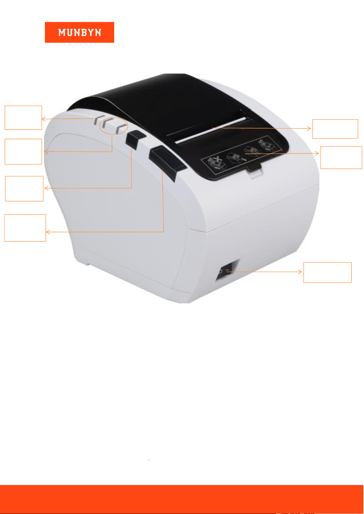
1.3.1.Control Panel(Front View)
Figure 1- 2 Control Panel
Paper cutter:cut the receipt paper
Power indicator:display the connection status of the machine power
Status indicator:display the printing status (blue: normal/red: error)
Feed button:press to feed the receipt paper
Cover open button:open the cover
Power switch:turn on the printer
Power
Indicator
Front Cover
Cover Open
Button
Paper Cutter
Error
Indicator
Power Switch
Feed
Button

Page7 of 21
ITPP047 Thermal Printer Hardware Manual
Version 1.00
1.3.2.Interface(Back View)
Figure 1- 3 Interface display
Power port:connect the power cable with this port.
Serial port:connect the serial cable with this port.
LAN port:connect the Lan cable with this port.
USB port:connect the USB cable with this port.
Cash drawer:connect your cash drawer with this port.
USB Port
Power Port
Serial Port
Cash Drawer
LAN Port

Page8 of 21
ITPP047 Thermal Printer Hardware Manual
Version 1.00
Figure 1- 4 Side view
1.3.3.Indicator
Figure 1- 5 Indicator

Page9 of 21
ITPP047 Thermal Printer Hardware Manual
Version 1.00
①POWER LED on
Means power connection properly.
②ERROR LED twinkles
Means out of paper, cutter or printing head overheat.
③PAPER LED on
Means lack of paper, no alarm means all goes well.
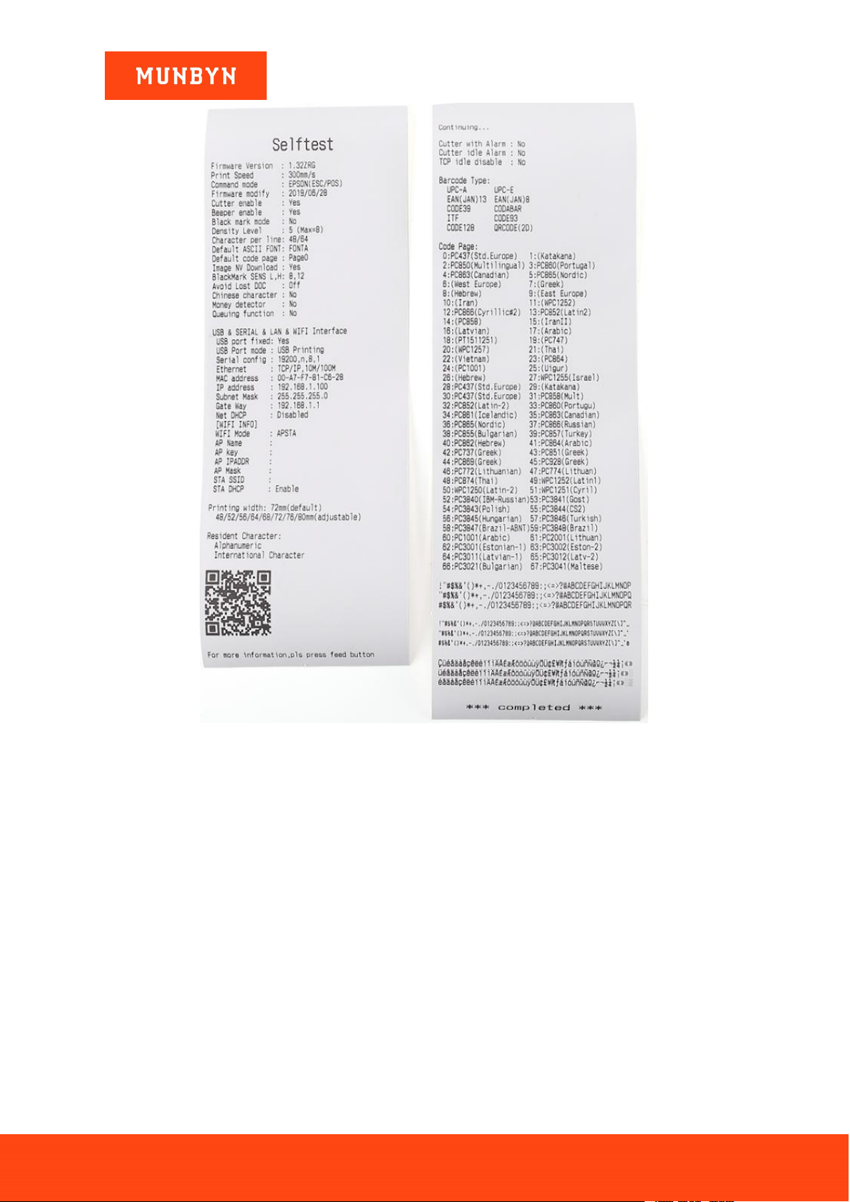
1.3.4.Self-test Page
make sure the printer is connected with the power and turn it off.
a. Press the “FEED” button and simultaneously turn on the power.
b. Hold on pressing the “FEED” button for about 2-3 seconds, release “FEED” button when the “ERROR”
and “PAPER LED” double-blinking at the same time.
c. The printer will automatically print out self-test paper including its status and configurations.
Page10 of 21
ITPP047 Thermal Printer Hardware Manual
Version 1.00
Figure 1- 6 Self-test page
1.3.5.Initialization
Make sure the printer is connected with the power and turn it off.
Press the “FEED” button and simultaneously turn on the power.
Hold on pressing the “FEED” button for about 20 seconds, then “ERROR LED” on until “ERROR” and
“PAPER LED” double- flash again, release the “FEED” button when buzzer alarming.
At this time the printer has been initialized, restoring factory settings.
1.3.6.Hexadecimal Mode
Other manuals for ITPP047
3
Table of contents
Other MUNBYN Printer manuals


