MV Heating Airo 5 Instruction manual

MV Heating UK Ltd
Unit 6
Second Avenue Business Park
Millbrook
Southampton
SO15 0LP
MV Heating UK LTD
+44 (0)2380 522345
MV Airo 5
WORKSHOP MANUAL
ED 1.02

+44 (0)23 8052 2345
1
MV Heating UK Ltd
Disclaimer:
This manual is intended to give an overview of the internal workings of MV
diesel heaters. As such, all work should be carried out by trained
professionals at their own discretion. Any action you take upon the
information in this manual is strictly at your own risk, and MV Heating will not
be liable for any losses and damages in connection with the use of this
information. Under no circumstances shall MV Heating or its affiliates,
suppliers, or installers be liable for any indirect, incidental, consequential,
special or exemplary damages, arising out of or in connection with these
manuals. We do not take any warranties about the completeness, reliability
and accuracy of this information. MV Heating assumes no responsibility or
liability for any errors or omissions from these manuals.

+44 (0)23 8052 2345
2
MV Heating UK Ltd
Contents
Heater Removal .................................................................................................3
Heater Installation .........................................................................................3
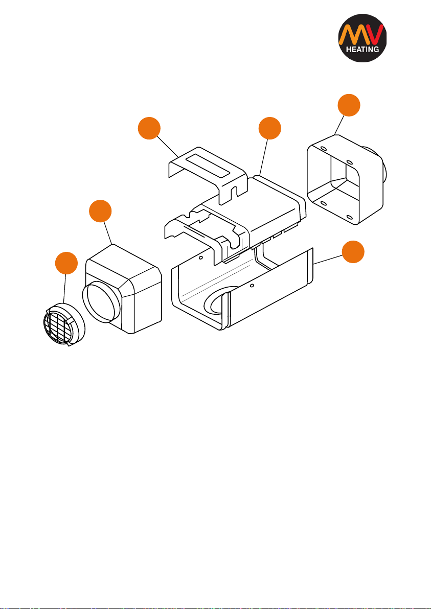
Heater Cases Diagram........................................................................................4
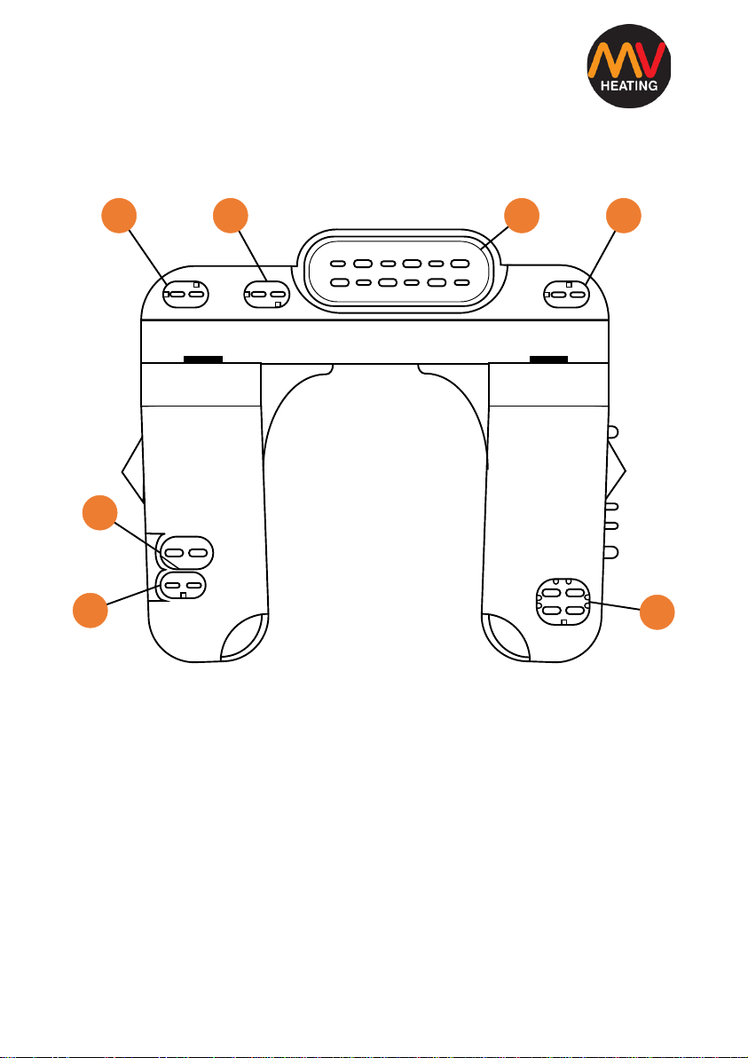
Internal Structure Diagram ................................................................................5
E.C.U. Connections Diagram ..............................................................................6
Removing and Refitting of Parts ........................................................................7
Pre-Checks and Notes ....................................................................................7
Part 1: The Case Assembly.............................................................................8
Part 2: The Overheat Sensor..........................................................................9
Part 3: The E.C.U. .........................................................................................10
Part 4: The Air Motor ...................................................................................11
Part 5: The Burner and Glow Pin Assembly Removal ..................................12
Part 5 Cont’d: The Burner and Glow Pin Assembly Refit .........................13
Part 5 Cont’d: The Burner and Glow Pin Assembly Refit.........................14
Part 6: The Combustion Chamber................................................................15
Part Numbers...................................................................................................16
Notes................................................................................................................17
Note: The following flow charts will refer to the exploded diagrams, or figures
as (F:P), where ‘F’ donates the figure, and ‘P’ donates the part in that figure.
For example (2:4) would mean ‘Figure 2: Part 4’.

+44 (0)23 8052 2345
3
MV Heating UK Ltd
Heater Removal
To remove the heater from its installation positions, follow these steps:
1. Disconnect the vehicle’s battery.
2. Disconnect any ducting secured to the heater’s inlet, or outlet caps.
3. Remove the ECU cover (1:3) from the top cover (1:4) to access the
main heater connection.
4. Disconnect main wiring harness connector from heater.
5. Disconnect the fuel supply line from heater’s fuel inlet.
6. Disconnect the fuel pump by pressing the spring clip down and pulling
away the connector.
7. Disconnect the combustion air intake and exhaust pipe from the
bottom of the heater.
8. Remove the four M6 nuts and washers from the base of the heater.
9. Remove the heater and discard the mounting gasket.
Heater Installation
To reinstall the heater back into position, follow these steps:
1. Locate heater into position with a new mounting gasket and secure
with the four M6 nuts and washers to 6 + 1 Nm.
2. Connect and secure fuel supply line to the heater’s fuel inlet.
3. Connect and secure the combustion air intake and exhaust pipe to the
heater.
4. Route the fuel cable to the fuel pump and reconnect it.
5. Connect the main wiring harness connector to the E.C.U. and replace
the cover (1:3).
6. Reconnect the vehicle’s battery.
7. Fully bleed the fuel supply system, by turning the heater on and off.
Ignition failure will occur until the system has been bled.

+44 (0)23 8052 2345
4
MV Heating UK Ltd
Heater Cases Diagram
3
1
6
4
2
5
Figure 1
1. Inlet Cap 2. Outlet Cap 3. E.C.U. Cover
4. Top Cover 5. Bottom Cover 6. Grill

+44 (0)23 8052 2345
5
MV Heating UK Ltd
Internal Structure Diagram
Figure 2
1. Overheat Sensor 2. E.C.U. 3. Air Motor Assembly
4. Air Motor Gasket 5. Burner 6. Glow Pin (& Flame Sensor)
7. Combustion Chamber 8. ‘O’ Ring 9. Heat Exchanger
10. Insulating Bush
2
67
5
4
31
9
8
10

+44 (0)23 8052 2345
6
MV Heating UK Ltd
E.C.U. Connections Diagram
1
2
7
65
43
Figure 3
1. Overheat Sensor 2. Glow Pin 3. Fuel Pump
4. Temperature Sensor 5. Main Wiring Harness 6. Empty
7. Air Motor

+44 (0)23 8052 2345
7
MV Heating UK Ltd
Removing and Refitting of Parts
Pre-Checks and Notes
•All gaskets located between the disassembled parts must always be
discarded and replaced.
•All the parts that have been disassembled should be cleaned with
appropriate cleaning fluid and blown dry with pressurized air.
•Any sealing compound on parts must be carefully and completely
removed before attempting to refit.
•All disassembled parts should be Inspected for damage (cracks,
distortion, wear, etc.) and replaced as required.
You should also regularly inspect all electrical connectors and wiring for
corrosion, loose contacts, or wrong crimping, etc. and repair as required.

+44 (0)23 8052 2345
8
MV Heating UK Ltd
Part 1: The Case Assembly
Tools:
•1 x Small Flat-Bladed Screwdriver
Removing the Cases:
1) Remove the heater from its installation position.
2) Remove the inlet cap (1:1) with grill (1:6) (if attached) using a screwdriver
to separate from bottom and top cases.
3) Remove the outlet cap (1:2) the same way, making sure it doesn’t catch
on the heat exchanger.
4) Remove the E.C.U. cover (1:3) and top case (1:2) together by sliding away
from the bottom case.
5) Remove the bottom (1:5) case by pulling away from air motor lugs first.
Refitting the Cases:
1) Ensure all four rubber insulating bushes (2:9) are located on the tabs of
the heat exchanger (2:8) first before refitting the cases.
2) Replace bottom case (1:5), ensuring the air motor lugs sit inside the
appropriate holes.
3) Replace top case (1:4), ensuring that the tabs are locate inside the
bottom case correctly.
4) Refit the outlet cap (1:2), ensuring that it is orientated correctly.
5) Refit the inlet cap (1:1), ensuring that it is orientated correctly.

+44 (0)23 8052 2345
9
MV Heating UK Ltd
Part 2: The Overheat Sensor
Tools:
•1 x Small Flat-Bladed Screwdriver
Removing the Overheat Sensor:
1) Remove the cases (Part 1).
2) Unplug the overheat sensor (2:1) from the E.C.U. (two blue wires).
3) Slide the overheat sensor off the heat exchanger (2:9). It can be a tight fit,
and a small flat-bladed screwdriver can be used to ease it off as
necessary.
Refitting the Overheat Sensor:
1) Replace the overheat sensor onto the heat exchanger.
2) Plug the overheat sensor back into the E.C.U. (2:2), paying attention to its
correct orientation.
3) Replace the cases (Part 1).

+44 (0)23 8052 2345
10
MV Heating UK Ltd
Part 3: The E.C.U.
Tools:
•1 x 3mm Hex Key
Removing the E.C.U.:
1) Remove the cases (Part 1).
2) Disconnect the overheat sensor plug (3:1), glow pin plug (3:2), and fuel
pump plug (3:3) from the ECU.
3) Loosen the four-pin air motor plug (3:7) from the E.C.U. its size will
prevent it from being fully disconnecting.
4) Remove the 2 x 3mm hex bolts from the top of the E.C.U.
5) The ECU can now be removed, allowing the final four-pin connector to
also be fully disconnected.
Refitting the E.C.U.:
1) Insert the four-pin connector (3:7) into the appropriate slot in the ECU,
paying attention to its orientation.
2) Reinstall the E.C.U. securing it in place with the 2 x hex bolts located on
top. Tighten to 3.0 ± 0.3 Nm.
3) Reconnect the rest of the connectors (3:1), (3:2), and (3:3), back into their
correct connections, paying attention to their orientation.
4) Replace the cases (Part 1).

+44 (0)23 8052 2345
11
MV Heating UK Ltd
Part 4: The Air Motor
Tools:
•1 x 4mm Hex Key
Removing the Air Motor:
1) Remove Cases (Part 1) and E.C.U. (Part 3).
2) Remove the 8 x bolts located around the bottom of the air motor (2:3).
3) Carefully remove the air motor by tilting it to one side so that the
combustion intake clears the heat exchanger.
4) The air motor gasket (2:4) can be removed and discarded once the air
motor is clear.
Refitting the Air Motor:
1) Place a new air motor gasket (2:4) around the end of the heat exchanger.
2) Refit the air motor (2:3) back into position.
3) Fit the 8 x hex bolts around the base of the air motor and tighten to 4.0 ±
0.4 Nm.
4) Refit E.C.U. (Part 3) and cases (Part 1).

+44 (0)23 8052 2345
12
MV Heating UK Ltd
Part 5: The Burner and Glow Pin Assembly Removal
Tools:
•1 x Small Flat-Bladed Screwdriver
•1 x 5.5mm Socket Screwdriver
•1 x Small Phillips Head Screwdriver
Removing the Assembly:
1) Remove the cases (Part 1) the E.C.U. (Part 3) and the air motor (Part 4).
2) Using a flat-bladed screwdriver, gently push the glow pin grommet fully
through toward the burner.
3) Using the socket screwdriver, remove the 3 x 5.5mm hex screws from the
burner (2:5), and place to one side.
4) Use the flat-bladed screwdriver to gently push in the fuel inlet grommet
toward the burner, being careful not to split it.
5) Slightly lift the burner from the top away from the combustion tube and
pull slightly toward the top of the heat exchanger.
6) Rotate the burner 180° to the right (it will not fully rotate the other way)
so the glow pin side faces up, and pull the burner out of the fuel inlet
hole.

+44 (0)23 8052 2345
13
MV Heating UK Ltd
Part 5 Cont’d: The Burner and Glow Pin Assembly Refit
Tools:
•1 x Small Flat-Bladed Screwdriver
•1 x 5.5mm Socket Screwdriver
•1 x Small Phillips Head Screwdriver
Glow Pin Removal:
1) One the burner has been removed, use the Phillips head screwdriver to
loosen the screw holding the glow pin (2:6) in place.
2) Gently remove the glow pin from out of its housing (the glow pin can be
tight to remove).
3) Once out of its housing, feed the glow pin through the correct hole (the
largest elongated one) located on the burner.
4) The burner and glow pin can now be inspected, cleaned and replaced as
necessary.
Glow Pin Refit:
1) Feed the glow pin back through the largest elongated hole on the burner
and reinsert it fully into position.
2) Tighten the small Phillips head screw onto the glow pin to 0.8 ± 0.08 Nm
to hold it securely in place.

+44 (0)23 8052 2345
14
MV Heating UK Ltd
Part 5 Cont’d: The Burner and Glow Pin Assembly Refit
Tools:
•1 x Small Flat-Bladed Screwdriver
•1 x 5.5mm Socket Screwdriver
•1 x Small Phillips Head Screwdriver
Refitting the Burner:
1) With the glow pin side of the burner facing upward, insert the fuel inlet of
the burner back into the appropriate hole.
2) Rotate the burner 180° to the left so that it faces the correct way and
gently push it toward the combustion chamber.
3) Insert and tighten the 3 x 5.5mm hex screws back into the burner to 2.5 ±
0.25 Nm to hold it in place.
4) Using the flat-bladed screwdriver, carefully push the fuel inlet grommet
fully into position using some lubricant like WD40 as necessary.
5) Feed the glow pin back through the glow pin hole.
6) Fully insert the glow pin grommet into the hole to create a clean seal.
7) Refit the air motor (Part 4), E.C.U. (Part 3), and cases (Part 1).

+44 (0)23 8052 2345
15
MV Heating UK Ltd
Part 6: The Combustion Chamber
Tools:
•1 x 3mm Hex Key
•1 x Pliers
Removing the Combustion Chamber:
1) Remove the cases (Part 1), the E.C.U. (Part 3), the air motor (Part 4), and
the burner assembly (Part 5).
2) Undo the 4 x 4mm hex bolts from the top of the combustion chamber.
3) Using a pair of pliers, remove the combustion chamber (2:7). This can be
stiff as the rubber O-ring can become bonded between the chamber
and heat exchanger.
4) Remove the rubber O-ring (2:8) from its position inside the combustion
chamber and discard.
Refitting the Combustion Chamber:
1) Place a new rubber O-ring (2:8) into the recess of the combustion
chamber.
2) Insert the combustion tube (2:7) back into the heat exchanger (2:9).
3) Replace and tighten the 4 x hex bolts into the top of the combustion
chamber to 4 ± 0.4 Nm to secure it in place.
4) Replace the burner assembly (Part 5), the air motor (Part 4), the E.C.U.
(Part 3), and the cases (Part 1).

+44 (0)23 8052 2345
16
MV Heating UK Ltd
Part Numbers
Part (Voltage) Part Number
1) Heat Exchanger: A5Z-001
2) O-Ring: A5Z-002
3) Combustion Tube: A5Z-003
4) Burner Assembly: A5Z-004
5) Gasket: A5Z-005
6) Air Motor (12V/24V): A5C-006/A5A-006
7) Insulation Bushes: A25Z-007
8) E.C.U. (12V/24V): A5C-009/A5A-009
9) Glow Pin (12V/24V): A5C-014/A5C-014
10) Overheat Sensor: A25Z-016
11) Inlet Cap: A5Z-027
12) Outlet Cap: A5Z-028
13) E.C.U. Cover: A5Z-024
14) Top Cover: A5Z-025
15) Bottom Cover: A5Z-026
16) Grill: A5Z-029
17) Fuel Pump(12V/24V) AHC-023/AHA-023

+44 (0)23 8052 2345
17
MV Heating UK Ltd
Notes
………………………………………………………………………………………………………………………..
………………………………………………………………………………………………………………………..
………………………………………………………………………………………………………………………..
………………………………………………………………………………………………………………………..
………………………………………………………………………………………………………………………..
………………………………………………………………………………………………………………………..
………………………………………………………………………………………………………………………..
………………………………………………………………………………………………………………………..
………………………………………………………………………………………………………………………..

+44 (0)23 8052 2345
18
MV Heating UK Ltd
Table of contents
Other MV Heating Heater manuals
Popular Heater manuals by other brands

Oceanic
Oceanic OCEABH1500W user manual

Desa
Desa RCLP50 owner's manual

Nortek
Nortek Reznor 85 Installation and operating manual

Tecnosystemi
Tecnosystemi Apply air ARIA2 ELEGANCE CR user manual

Fondital
Fondital IST 03 F 014 - 02 Installation and maintenance manual

Somogyi Elektronic
Somogyi Elektronic Home FK 350 WIFI instruction manual

Sygonix
Sygonix 1524062 operating instructions

Etherma
Etherma LAVA-BASIC-500DM Installation and usage instructions

Somogyi Elektronic
Somogyi Elektronic home FK1 instruction manual

Midea
Midea NY2009-20M owner's manual

Ruffneck
Ruffneck FE2 Series Developer's manual

Bionaire
Bionaire BRH6403ERE-CN Instruction leaflet