MV Heating MV MY20 Economie User manual

MV MY20
Economie
DIESEL POWERED
AIR HEATER
INSTRUCTION MANUAL
ED 1.00
MV MY20 Economie
MV Heating UK Ltd
Unit 6
Second Avenue Business Park
Millbrook
Southampton
SO15 0LP
MV Heating UK LTD
+44 (0)2380 522345

+44 (0)23 8052 2345
1
MV Heating UK Ltd
Preface
Thank you for purchasing the ‘MV MY20 Economie’ air heater. This
instruction book describes the structures, working principles, installation and
operation of the MV MY20 Economie. For correct use of the heater, please
read this instruction book carefully before installation and use. The
instruction book should be saved in a convenient place for reference later.
Note
•This instruction book is subject to revision without notice, but the
instruction book is in conformity to the purchased product.
•Our effort is to explain all questions you may have. If you have any
doubts or find anything incorrect in this manual, please contact us
directly.
•Check the heater for any damage when unpacking and contact the
dealer immediately if anything is found.
•If any troubles arise during operation, please contact MV Heating or
other customer service stations authorized by this company. We shall
do our best to provide service to you.
Comply with the operation manual for installation and operation, to
ensure prolonged and reliable use.

+44 (0)23 8052 2345
2
MV Heating UK Ltd
Contents
Introduction .......................................................................................................4
Technical Data....................................................................................................5
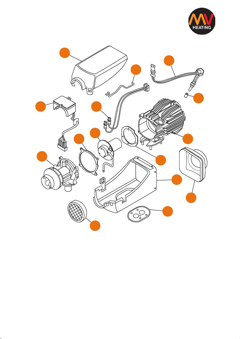
MV Airo 2 Boost Internal Structure............................................................6
Kit Contents........................................................................................................7
Installation .........................................................................................................9
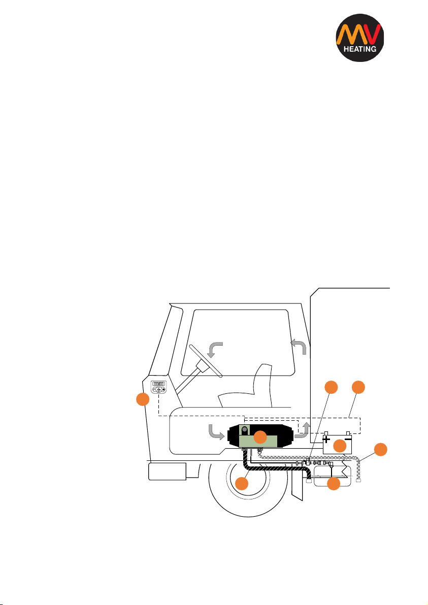
Installation of the Main Heater Body.........................................................9
Wiring Harness Connector Positions ...........................................................11
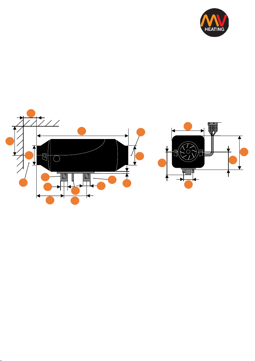
Installation: Mounting..................................................................................12
Installation: Ducting and Pipework..............................................................14
Exhaust System ........................................................................................15
Combustion Air Intake .............................................................................16
Installation: Fuel Lines .................................................................................17
Installation of Fuel Lines ..............................................................................18
Fuel Standpipe .............................................................................................21
MV MY20 Wiring Diagram ...........................................................................23
Timer and Rheostat Control Plugs ...........................................................24
Timer Operation...........................................................................................25
Setting the Time and Date .......................................................................26
Adjusting the Time and Date ...................................................................26
Power On/Off...........................................................................................27
Changing Display –Temperature & Heat Output Level...........................27

+44 (0)23 8052 2345
3
MV Heating UK Ltd
Adjusting the Heating Run Time .......................................28
Fan Only Mode.........................................................................................29
Fuel Priming Mode...................................................................................29
Timer Setting............................................................................................30
Pairing Remote Control............................................................................31
Using the Remote Control........................................................................31
Maintenance....................................................................................................32
Fault Codes.......................................................................................................33

+44 (0)23 8052 2345
4
MV Heating UK Ltd
Introduction
The main equipment of the MV MY20 Economie air heater (hereinafter
referred to as ‘the heater’) is a small fuel furnace controlled by a single-chip
micro-processor. Its furnace body (the heat exchanger) is located in the hood
shaped case, which serves as an independent air passage. Cold air is drawn
into the air passage by the fan and blown out as hot air. The air is warmed to
around 90° above the ambient temperature. The heat can be supplied by the
heater to the driver’s cab and passenger’s compartment independently from
the engine, using ducting and joiners to accommodate most applications. The
basic schematic diagram is shown in Fig I.
The heater is fully automatically controlled. It features a compact structure,
easy installation, low running costs, easy maintenance and is safe and
reliable.
1. Control switch
2. Heater Body
3. Fuel Pump
4. Wiring Harness
5. Vehicle’s Battery
6. Vehicle’s Fuel Tank
7. Exhaust Pipe
8. Combustion Air
Intake
Figure I
1
25
6
3 4
8
7

+44 (0)23 8052 2345
5
MV Heating UK Ltd
Technical Data
Power (Watt)
2000
Heating Medium
Air
Fuel Consumption (l/h)
0.28-0.10
Fuel
Diesel
Weight
Approx. 2.7KG
Air Flow Rate (Without Counterpressure)
105
Power Consumption at start
8-34
rated Voltage
12/24V
Dimensions
210 X 115 X 122
Operating Range
10.5 - 18V
Operating Voltage
10.5-18V (12V
18V-28V (24V)
Ambient Temperature (Heater)
-40°C to 70°C
(Fuel Pump)
-40°C to 50°C
Maximum Air Inlet Temperature
40°C

+44 (0)23 8052 2345
6
MV Heating UK Ltd
MV Airo 2 Boost Internal Structure
Figure II
1. Heat exchanger 2. Burner Gasket 3. Burner Assembly
4. Air Motor Gasket 5. Air Motor 6. ECU
7. Overheat Sensor 8. Spring Clip 9. Glow Pin
10. Glow Pin Screen 11. Top Case 12. Bottom Case
13. Outlet Cover 14. Inlet Grill 15. Mounting Gasket
14
15
12
2
1
10
9
8
11
7
3
4
5
6
13

+44 (0)23 8052 2345
7
MV Heating UK Ltd
4
5
6
2
1
12
14 17
18
19
7
11 8
13
20
21
22
16
15
10
3
9
10
Kit Contents
The kit includes everything necessary for installation.
Figure III

+44 (0)23 8052 2345
8
MV Heating UK Ltd
1. Main heater unit 2. Inlet Grill
3. Outlet Case 4. 60mm Vent
5. Hose Clip 6. 60mm Ducting
7. 24mmExhaust Clamp 8. 24mm Exhaust
9. P-Clip 10. 24mm Exhaust Silencer
11. 24mm Hose Clip 12. 24mm Combustion Air Hose
13. Combustion Air Filter/Silencer 14. Main Wiring Harness
15. Main Control Unit 16. Remote Control Fob
17. Fuel Pipe 18. Fuel Pump
19. Fuel Pump Mount 20. Fuel Filter
21. Rubber Fuel Line Joiners & Connectors 22. Fuel Standpipe
Figure III shows the basic principle for installation. The position and ways of
fixing of various parts may vary from one vehicle/boat to another, but the
general principles remain the same.
Attention:
•Do not mount the heater near any flammable sources
•Do not install the heater in closed spaces without ventilation
•Do not place the heater near anything that can cause a blockage
•Do not mount the heater near any water sources and protect it from
any splashing or road debris

+44 (0)23 8052 2345
9
MV Heating UK Ltd
Installation
Installation of the Main Heater Body
For the ease of servicing, fault finding and air flow it’s recommended that the
main body is placed in an area with easy access. Figure V shows the minimum
distances required.
Figure IV
A. Air heating Outlet B. Air Inlet
C. Combustion air inlet D. Fuel inlet
E. Exhaust outlet
Choose a flat installation surface, any undulations could cause the case to
twist and will not ensure an even mount. Make sure there are no foreign
bodies between the bottom of the heater and the installation surface itself.
This will ensure a good seal between the two.
DIMENSIONS: mm
A
B
305
60
25 24
130
55
130
60
7
30
15
0
115
122
65
44
90
C
D
E

+44 (0)23 8052 2345
10
MV Heating UK Ltd
Installation: Angle
All positions suggested are examples. Other locations are possible so long as
they correspond to the proper installation guidelines and requirements.
1. Heater air intake 2. Glow pin position 3. Direction of air flow
Figure V
Figure V shows the ideal installation position of the heater; with exhaust
pointing downward. Depending on its location it can be tilted by 30° with the
air flow and hot air outlet facing the bottom. It can also be tilted on its
longitudinal axis by 90° so long as the glow pin position points upward. During
usual operation the heater can deviate by 15° each way with vehicle
movement without impaired function of the heater.
1
30°
3
90°
2
1

+44 (0)23 8052 2345
11
MV Heating UK Ltd
Wiring Harness Connector Positions
The main connector coming off the heater can be moved to the other side of
the heater if necessary. To do this you must first remove the air inlet grill by
twisting it counter clockwise until it is removed. Next, remove the top cover
by lifting the two front flaps near the air inlet. You can then lift out the entire
innards of the heater (heat exchanger to fan motor and all) removing the
cable from the rubber securing bush and rerouting it underneath the fan
motor where it can then sit in the cut-out on the opposite side. Ensure the
rubber bush is properly inserted and the heat exchanger is back securely in
position, then simply replace the lid and grill back in position.
Note: Ensure the
bottom cover fits
correctly inside the
groove of the lid.
Figure VI

+44 (0)23 8052 2345
12
MV Heating UK Ltd
Installation: Mounting
The chosen mounting surface should be flat, and you will need to drill the
appropriate size hole for the exhaust, combustion air inlet, fuel inlet and
mounting bolts. It is a good idea to mount the heater on the supplied
mounting bracket, particularly if the original mounting surface is thinner than
1.5mm.
A. Mounting Gasket B. Mounting Plate
Figure VII
Note: The mounting plate shown in figure VII may differ in overall size and
the circular flange may not be present, however the heater footprint will
remain the same.
148
7.5
170
85
125
2
5
25 35.5
7.5
26
12 44
18
55
DIMENSIONS: MM
A
B

+44 (0)23 8052 2345
13
MV Heating UK Ltd
Installation: Mounting (Cont’d)
(Above) (Above)
Securing the heater to the floor Securing the heater to the wall
Figure VIII
1. Check that the fan wheel spins freely and that there is sufficient clearance
between the heater and the vehicle floor
2. Ensure that the mounting surface is flat and smooth
3. The mounting gasket supplied must be fitted
4. The vehicle wall must be flat and smooth
5. Mounting bracket
6. M6 Washer
7. M6 Nut
Figure VIII shows the mounting positions on a vehicle’s floor and wall.
1
4
6
5
3
2
1
43
6
5
21

+44 (0)23 8052 2345
14
MV Heating UK Ltd
BCD
F
E
A
Installation: Ducting and Pipework
Using the MV MY20 Economie as an example:
Figure IX
1. Ducting AND/OR Grill 2. Main Heater body
3. 60mm Hose Clip 4. 60mm APK Ducting
5. 60mm Hose Clip 6. 60mm Reducer
7. 80mm Directional Vent
Figure X
A. Heater’s hot air outlet B. 60mm hose clip
C. 60mm APK ducting D. 60mm ‘Y’ branch
E. 60mm Reducer F. 80mm outlet vent
123465 7

+44 (0)23 8052 2345
15
MV Heating UK Ltd
Installation: Ducting (Cont’d)
Ducting Can be installed as shown on the previous page. Extra outlets can be
installed to fit your own needs however you should ideally not fit more than
the maximum of 3 outlets to the MY20. The MY20 uses 60mm ducting.
Exhaust System
Note: Do not work on the exhaust system unless the heater has been
switched off for over an hour and wear safety gloves if necessary. All types of
combustion produce high temperatures and toxic fumes and must be
installed in accordance with these instructions.
The flexible exhaust pipe can be shortened to no less than 20cm and should
not exceed a length of 2.3m, depending on the installation parameters. Route
the exhaust pipe from the heater to a suitable outlet, ensuring that is securely
fitted to the heater using the clamp supplied in the kit.
As the exhaust gets very hot during operation, it should be installed in such a
way that will not cause damage to the vehicle. Ensure that it has sufficient
clearance of heat sensitive parts; paying close attention to fuel lines (plastic
and copper) and electrical components. Make sure that the outlet ends in
open air and does not point in the direction of travel. The whole system
should also point downwards and if necessary, a 5mm hole should be drilled
near the bottom to drain off any condensation. You should also route the
exhaust so that the fumes are not taken back in by the air intakes of the
heater and ensure that the outlet does not get blocked by anything like road
debris etc.

+44 (0)23 8052 2345
16
MV Heating UK Ltd
Figure XI
1. Heater Body 2. 25mm Combustion Air Inlet
3. Combustion air inlet clamp 4. Combustion air pipe
5. Combustion air silencer OR end cap 6. 24mm Exhaust outlet
7. Exhaust clamp 8. 24mm Exhaust pipe
9. Exhaust silencer 10. Exhaust end cap
Combustion Air Intake
Like the exhaust pipe the combustion air intake can be shortened to up to
20cm or lengthened to no more than 2m, again depending on installation
conditions. Some models can also be fitted with a combustion air silencer to
reduce the noise of the air intake; this is ultimately down to personal
preference.
In some situations, an air filter may be required to stop dust or debris making
its way up the air pipe.
1
2
3
4
567810
778
9

+44 (0)23 8052 2345
17
MV Heating UK Ltd
Installation: Fuel Lines
Note: When installing, priming, repairing fuel lines etc. there is always a risk
of injuries due to flammable and toxic sources. Take all the necessary safety
precautions when fitting any fuel line or fuel line parts.
DO NOT:
•Smoke
•Use naked flames
•Inhale fumes
When working on or near any fuel lines or parts!
DO:
•Ensure the engine and heater are switched off before attempting any
and all work on the fuel line installation or repair
•Cut any fuel line with a sharp knife to ensure a clean cut free from
crushes and burrs
•Make sure the pipe from the fuel pump to the heater is on a gradual
rise
•Ensure fuel pipes are fastened safely to prevent noise rattle and
securely fitted to prevent any damage
•Route the fuel pipes so that vehicle vibration and movement will not
have any lasting effects on the service life
•Route the fuel line away from any and all heat sources. Ensure
adequate clearing from heat sources if it cannot be avoided or use a
suitable heat shield
•Make sure all connectors are fastened securely to prevent dripping of
fuel, particularly onto hot surfaces or electrical components.
File down any drill holes to again ensure an even mounting surface. Tighten
the M6 bolts provided to a torque setting of 6Nm+1Nm.

+44 (0)23 8052 2345
18
MV Heating UK Ltd
Installation of Fuel Lines
Figure XII
1. Fuel Tank 2. Fuel Standpipe 3. Fuel line connector hose clip
4. Fuel Line 5. Fuel line connector 6. Fuel Filter
7. Fuel Pump 8. Damper 9. Heater Body
The vehicles own fuel tank can be used to supply the heater, a separate tank
can be used if necessary. If a separate tank has been used, please ensure that
it is not installed in the driver or passenger cab and is away from anything
that could cause a fire risk or inhaling of toxic fumes. Do not fit the heater
below the level of fuel, to avoid syphoning of fuel into the heater.
Always fit the fuel pump on the anti-vibration mount securely onto the
vehicle. Ensure the outlet of the fuel pump tilts upward. The correct angle is
shown in figure XIII.
2
3 4
5
6
78
9
1
2000-6800mm
500-1200mm

+44 (0)23 8052 2345
19
MV Heating UK Ltd
A
B
C
1
2
3
90°
0°
15°
35°
E
F
D
4
Where possible the fuel line should ideally be placed uphill to
the fuel pump to ensure ideal bleeding of the fuel line.
1. Heater Body 2. Max. Fuel Level
3. Min. Fuel Level 4. Fuel Pump
Fuel Pump Angle & Suction Height
A. 3000mm B. 500mm
C. 2000m D. Not acceptable
E. Acceptable (between 15-90°) F. Not acceptable
Figure XIII
Figure XIII shows the ideal way to mount the fuel pump.
Table of contents
Other MV Heating Heater manuals
Popular Heater manuals by other brands

Bimar
Bimar HO427 Instruction book

Zibro
Zibro Kamin SRE 166 (Type B) Service manual

Reznor
Reznor UDBP Installation & operation

Eliz
Eliz EWH 200 operating instructions

Pinnacle Climate Technologies
Pinnacle Climate Technologies REMINGTON REM-60V-GFA-O User's manual & operating instructions

ecofort
ecofort ecoheat Hybrid-T instruction manual

REMKO
REMKO HTL 250-EC operating manual

Soleus Air
Soleus Air MS-14R owner's manual

Pinnacle Climate Technologies
Pinnacle Climate Technologies Master MH-45-KFA User's manual & operating instructions

Blumfeldt
Blumfeldt 10032516 manual

Sencor
Sencor SFH 6010BL user manual

Müssel
Müssel HCD 60 M 50 T operating instructions