Mychef QUICK 1 User manual

mychefcooking.com
TECHNICAL SUPPORT SERVICE MANUAL QUICK 1 | QUICK 1T -DT.MS. QI. 2202.2
1
QUICK
QUICK 1 | QUICK 1T
Technical Support Service Manual

mychefcooking.com
TECHNICAL SUPPORT SERVICE MANUAL QUICK 1 | QUICK 1T -DT.MS. QI. 2202.2
2
INDEX
1. DISASSEMBLY FOR SERVICE ACCESS..................................................................... 4
1.1. Rear disassembly ............................................................................................................... 4
1.2. Dismantling the side panel ............................................................................................... 4
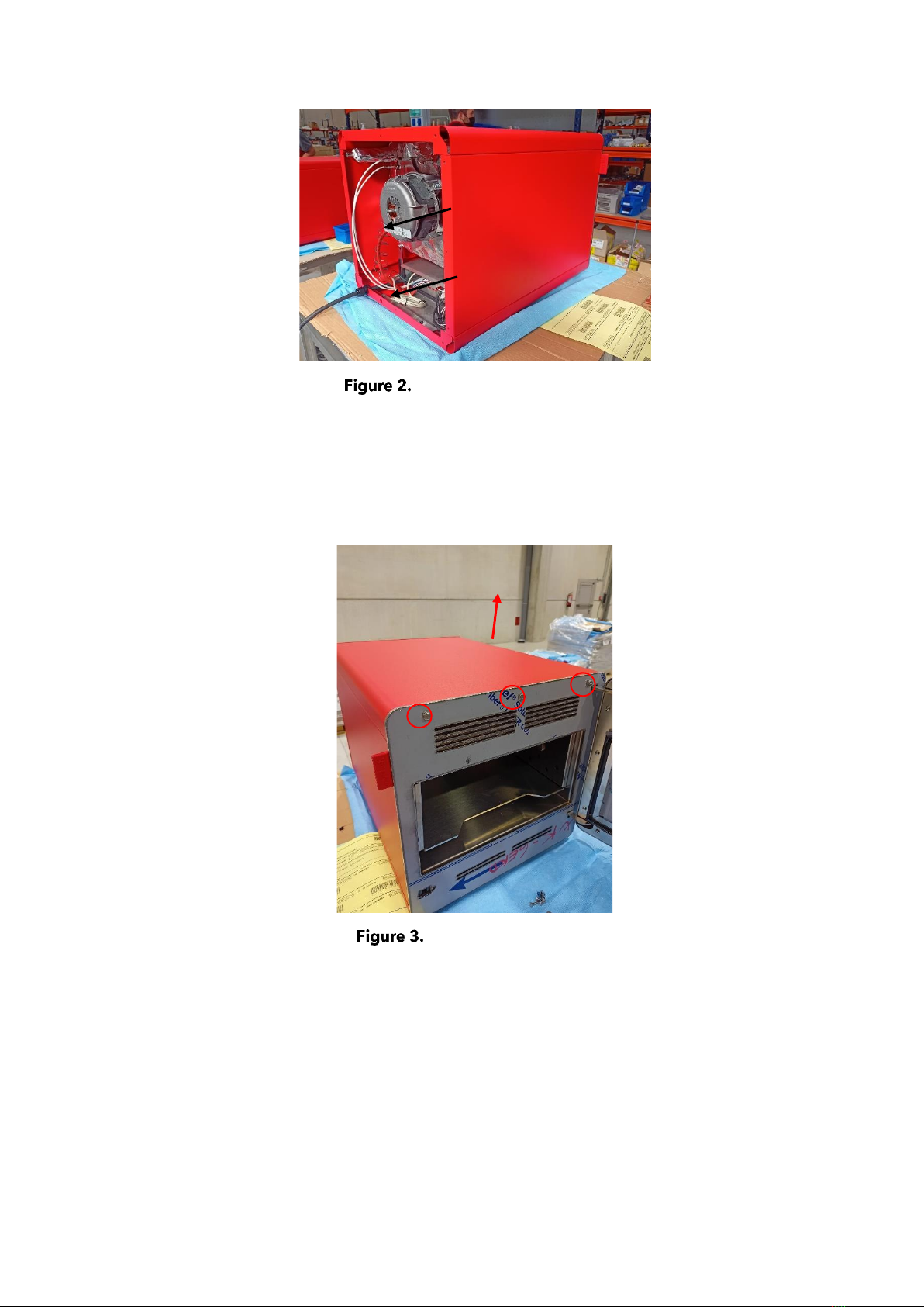
1.3. Dismantling the top ........................................................................................................... 5
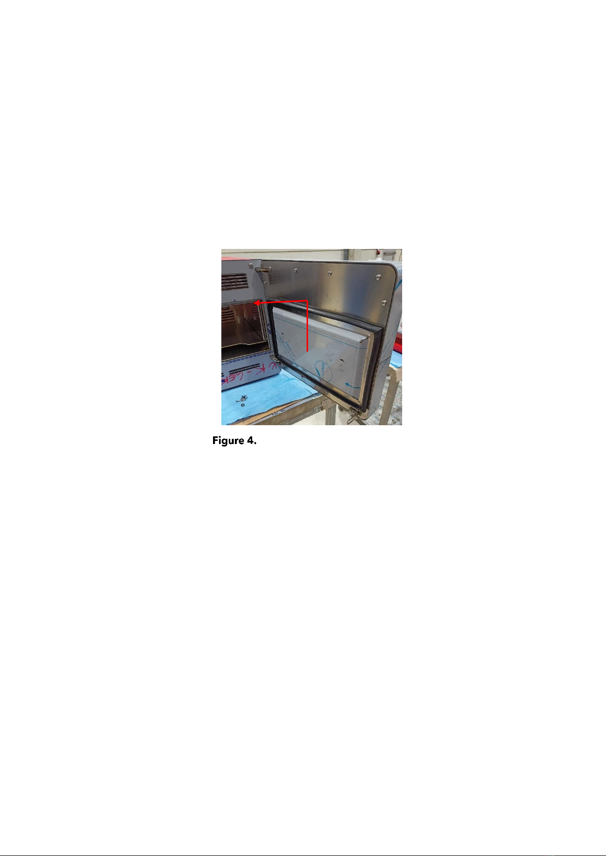
1.4. Dismantling the door......................................................................................................... 6
1.4.1. Door gasket plate.................................................................................................... 6
1.4.2. Inner clamping plate............................................................................................... 6
1.5. Disassembly of the convection fan cover plate.............................................................. 8
2. TROUBLESHOOTING ............................................................................................ 10
2.1. Checking electrical elements ......................................................................................... 10
2.2. Checking power supplies ............................................................................................... 10
2.2.1. Single-phase models ............................................................................................ 10
2.2.2. Safety thermostat................................................................................................... 11
2.2.3. Status LED relay board ......................................................................................... 11
2.2.4. Communications cable......................................................................................... 12
2.2.5. Control board ........................................................................................................ 12
2.3. Solutions to common problems..................................................................................... 12
2.3.1. The oven does not turn on ................................................................................... 12
2.3.2. The oven will not start........................................................................................... 13
2.3.3. The door is locked................................................................................................. 14
2.3.4. The oven does not heat........................................................................................ 14
2.3.5. Oven switches itself off or electronics do not respond..................................... 15
2.3.6. Oven burns food ................................................................................................... 15
2.4. Automatic error detection .............................................................................................. 15
2.4.1. Mychef QUICK ....................................................................................................... 15
3. CONFIGURATION MENU...................................................................................... 18
3.1. Access password.............................................................................................................. 18
3.2. Mychef QUICK 1............................................................................................................... 18
3.2.1. Oven configuration ............................................................................................... 19
3.3. Mychef QUICK 1T............................................................................................................. 23
3.3.1. Oven configuration ............................................................................................... 25
4. REPLACEMENT OF ELEMENTS ............................................................................. 28
4.1. Replacement of the chamber probe ............................................................................. 28
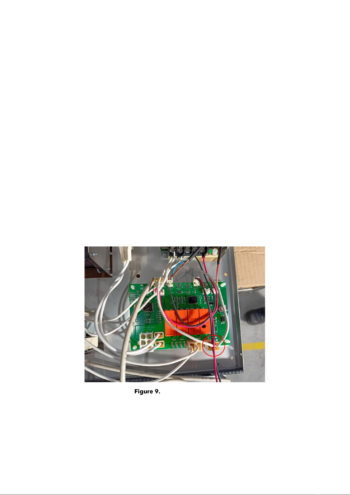
4.2. Replacement of the relay board..................................................................................... 29

mychefcooking.com
TECHNICAL SUPPORT SERVICE MANUAL QUICK 1 | QUICK 1T -DT.MS. QI. 2202.2
3
4.3. Replacement of contactors ............................................................................................. 30
4.4. Replacement of the control board................................................................................. 31
4.5. Replacement of the safety thermostat........................................................................... 33
4.7. Replacement of the oven motor turbine....................................................................... 35
4.8. Replacement of the oven motor..................................................................................... 35
4.9. Replacement of the oven motor seal............................................................................. 37
4.10. Replacement of the resistor.................................................................................. 38
4.11. Replacement of the latch hook............................................................................. 39
4.12. Replacing the door handle ................................................................................... 40
4.13. Replacing the door sensor.................................................................................... 40
4.14. Replacement of the cooling fan ........................................................................... 41
5. GENERAL WIRING DIAGRAM ............................................................................... 42
5.1. Mychef 4-relay plate ........................................................................................................ 42
5.2. Mychef Control QUICK 1................................................................................................. 43
5.3. Mychef control QUICK 1T ............................................................................................... 43

mychefcooking.com
TECHNICAL SUPPORT SERVICE MANUAL QUICK 1 | QUICK 1T -DT.MS. QI. 2202.2
4
1. DISASSEMBLY FOR SERVICE ACCESS
Caution: Before proceeding to disassemble any component, make
sure that the equipment is disconnected from the mains.
1.1.Rear disassembly
The following picture shows how to disassemble the back. Remove the M5 screws circled in
red and pull the rear backwards.
Dismantling the rear
1.2.Dismantling the side panel
The following image shows how to remove the side panels. Once the back panel has been
removed, slide the side panels towards the rear of the oven. Once the side panels are
released from the tabs, they can be removed very easily.

mychefcooking.com
TECHNICAL SUPPORT SERVICE MANUAL QUICK 1 | QUICK 1T -DT.MS. QI. 2202.2
5
Dismantling of the sides
1.3.Dismantling the top
To remove the roof, remove the M5 screws at the top of the front panel and remove the roof
from the oven.
Upper ceiling screws

mychefcooking.com
TECHNICAL SUPPORT SERVICE MANUAL QUICK 1 | QUICK 1T -DT.MS. QI. 2202.2
6
1.4.Dismantling the door
Before disassembling the door, remove the communications cable attached to the oven
control. See chapter 4.4.
The lock nose must also be removed prior to dismantling the door. See chapter 4.11.
1.4.1. Door gasket plate
To remove the door gasket plate, slide it upwards so that access to the screws of the inner
clamping plate is free.
Removal of door gasket plate
1.4.2. Inner clamping plate
To remove the inner fixing plate, the M4 screws must be removed. Once the inner fixing
plate has been removed, slide the door assembly upwards to remove it. Before removing
the door, disconnect the power cable from the control board (Section 4.4).

mychefcooking.com
TECHNICAL SUPPORT SERVICE MANUAL QUICK 1 | QUICK 1T -DT.MS. QI. 2202.2
7
Dismantling of the door

mychefcooking.com
TECHNICAL SUPPORT SERVICE MANUAL QUICK 1 | QUICK 1T -DT.MS. QI. 2202.2
8
1.5.Disassembly of the convection fan cover plate
The part that separates the cooking chamber with the fan and the heating element can be
removed to clean this area. First remove the tray and remove the screws from the side
plates. Once this operation has been carried out, we will have access to the screws that hold
the motor protection plate.
Dismantling tray and side plates
To remove the engine protection plate, remove the 4 screws that hold it in place, two at the
bottom and two at the top.
Dismantling of protection plate

mychefcooking.com
TECHNICAL SUPPORT SERVICE MANUAL QUICK 1 | QUICK 1T -DT.MS. QI. 2202.2
9
Once the screws have been removed, the plate must be tilted in order to remove it. It is not
possible to remove the plate straight up, as the filter holder will collide with the chamber
and will not allow the protective plate to be removed.
Removal of the turbine protection plate
Once it has been removed, cleaning can proceed.
Use extreme caution when cleaning this part of the oven. Leave the door
ajar and wait until the chamber fan stops.
When this process has been completed, replace the suction part of the chamber fan in
reverse order.

mychefcooking.com
TECHNICAL SUPPORT SERVICE MANUAL QUICK 1 | QUICK 1T -DT.MS. QI. 2202.2
10
2. TROUBLESHOOTING
2.1.Checking electrical elements
By entering the relay test mode, the oven can activate each relay individually, operating the
element connected to it (motor, chimney solenoid, light, etc.).
To check the relays, see chapter 3.2.1.5.
To check the door sensor and the safety thermostat of the motor, see chapter 3.3.1.8.,
3.3.1.6.
2.2.Checking power supplies
Before starting a troubleshooting process, check that the voltages are correctly reaching
the relay board, contactor and control board.
Dismantle the rear part to access the electronics (see 1.1).
2.2.1. Single-phase models
Single-phase models do not have a general contactor, so the voltage must be measured at
the relay board terminals.
Check input voltages
Check that the voltage N - L is 230VAC.

mychefcooking.com
TECHNICAL SUPPORT SERVICE MANUAL QUICK 1 | QUICK 1T -DT.MS. QI. 2202.2
11
2.2.2. Safety thermostat
The reset button is located on the back of the oven. If it has popped up, remove the plastic,
and tighten it.
Reset safety thermostat (rear)
2.2.3. Status LED relay board
Check that the power supply LED (green) is on.
Check that the relay board LED (red) flashes at a frequency of 10 times per second, if the
light flashes only once per second or is steady, there is a communication error.
Correct voltage LED on FA and Mychef relay board
If not, check the wiring between the contactor, power supply and relay board.
LED
Red
LED
green

mychefcooking.com
TECHNICAL SUPPORT SERVICE MANUAL QUICK 1 | QUICK 1T -DT.MS. QI. 2202.2
12
2.2.4. Communications cable
Check that the Modbus communications cable linking the relay board and the control board
is correctly inserted.
Modbus cable between boards
2.2.5. Control board
The control board should switch on automatically when powered. If not, check the modbus
cable and the control board.
2.3.Solutions to common problems
2.3.1. The oven does not turn on
The oven should switch on and standby when the power switch is pressed. To turn the oven
on, press the START/STOP button on the front panel of the oven.
If this is not the case, check the following points step by step. Before doing so, check that
the power supply cable is properly connected and that no safety mechanism has been
activated in the customer's installation (circuit breaker, circuit breaker, etc.).
Check the power supply, as specified in the chapter 2.2.

mychefcooking.com
TECHNICAL SUPPORT SERVICE MANUAL QUICK 1 | QUICK 1T -DT.MS. QI. 2202.2
13
2.3.2. The oven will not start
If a cooker does not start, the door sensor may not detect that the door is properly closed.
On QUICK ovens it is possible that the door sensor does not engage with the latch, adjust
the door and latch so that they are aligned.
Door sensor
Check the door sensor cable on the relay board.
Door sensor wiring
Door sensor

mychefcooking.com
TECHNICAL SUPPORT SERVICE MANUAL QUICK 1 | QUICK 1T -DT.MS. QI. 2202.2
14
2.3.3. The door is locked.
It is possible that the door may be blocked by the lock, if this happens, the side panels must
be removed (Section 1.2). On the back of the latch there is a tab that detects whether the
door is open or closed. If the latch has passed over the tab, it will lock the door. To unlock
it, press the tab with a flat screwdriver while gently opening the door.
Door sensor tab
2.3.4. The oven does not heat
Having started the oven and with a program running, check that the power contactor is
armed. If not, check that the voltage between poles A1 and A2 is 230VAC. If not, check the
wiring between the relay board and the contactor.
Power contactor
A1
A2
INDICATOR

mychefcooking.com
TECHNICAL SUPPORT SERVICE MANUAL QUICK 1 | QUICK 1T -DT.MS. QI. 2202.2
15
2.3.5. Oven switches itself off or electronics do not respond
Check that the safety thermostat does not trip, if it shuts down because the safety thermostat
trips, check if the temperature inside the chamber reaches more than 350ºC. If the
thermostat jumps before this, replace the safety thermostat. If it jumps to more than 350ºC,
the problem may be a contactor or the control board that does not regulate the temperature
correctly.
If the oven switches off and it is not because the safety thermostat has tripped, the problem
is the temperature on the control or relay board. To check the temperature on the control
board, with the oven on, press the time key for a few seconds. To check the temperature on
the relay board, with the oven on, press the fan button for a few seconds. Verify that these
temperatures are below 80ºC.
It is also possible that the chamber temperature sensor does not read correctly.
2.3.6. Oven burns food
Check that the temperature inside the oven coincides with the temperature shown on the
temperature display when the temperature button is pressed and held down. If the oven
regulates the temperature well, ask the user if this happens after a previous use of the oven
at high temperatures. If you wish to work at low temperatures after using the oven at high
temperatures, allow the oven to cool down for a reasonable period of time.
2.4.Automatic error detection
2.4.1. Mychef QUICK
During the preparation and execution of any of the programs available in the oven, errors
may occur due to equipment faults. If this is the case, the display of the QUICK 1 model will
show "Er", followed by the error or alarm number.
Error indicator
For the QUICK 1T version the display will show an error message according to the following
image.

mychefcooking.com
TECHNICAL SUPPORT SERVICE MANUAL QUICK 1 | QUICK 1T -DT.MS. QI. 2202.2
16
Error indicator for QUICK 1T ovens
The table below shows the different errors and alarms, as well as possible solutions to them.
Error
Internal definition
Clarification
0
NO ERROR
No error.
3
ERROR OVERTEMPERATURE PCB
Overtemperature PCB. Check that the cooling fans of
the electronics are working properly, that there is
enough space between the back and the wall, and
that the ambient temperature is not excessive.
4
ERROR COMMUNICATION
Communication between boards is not responding.
Check the cable connecting the power board and the
control board.
4.1
PCB ERROR RELAYS
Communication between boards not responding.
Check wiring.
5
EEPROM ERROR
Processor and EEPROM communication does not
work. Check the control board.
6
ENGINE ERROR
Motor error. Check motor wiring. Motor
overtemperature. Motor stuck
23
ERROR PROBE8 TEMP SENSOR
NOT CONNECTED
Chamber probe not connected. Check probe and
wiring.
24
ERROR PROBE8 TEMP SENSOR
SHORTED
Short-circuited chamber probe. Check probe and
wiring.
Table 1. Errors, alarms, and possible solutions

mychefcooking.com
TECHNICAL SUPPORT SERVICE MANUAL QUICK 1 | QUICK 1T -DT.MS. QI. 2202.2
17
Once the equipment has detected a serious error, it will not be able to function normally
until it is repaired.
Due to automatic checks the equipment may shut down to avoid a serious failure. Proceed
to switch it on as normal.

mychefcooking.com
TECHNICAL SUPPORT SERVICE MANUAL QUICK 1 | QUICK 1T -DT.MS. QI. 2202.2
18
3. CONFIGURATION MENU
3.1.Access password
Mychef ovens can request a password for parameter modification.
This functionality is currently disabled.
3.2.Mychef QUICK 1
To access the configuration menu, with the oven off, press the Preheat + START/STOP
buttons at the same time.
QUICK 1 panel
When entering the configuration menu, the three indicators on the top of the oven will light
up at the same time and the display will show P0:00.

mychefcooking.com
TECHNICAL SUPPORT SERVICE MANUAL QUICK 1 | QUICK 1T -DT.MS. QI. 2202.2
19
Example. Value of parameter 1 = 1
This menu is structured in a block of registers or parameters that contain all the oven
information.
To navigate through the parameters and to be able to view and edit values, we must first
select the parameter. To do this, press the Preheat key. The first part of the display will then
flash. The parameter number can then be changed with the -/+ keys.
To change the parameter value, press the CoolDown key. The second part of the display
will then flash. The parameter value can then be changed with the -/+ keys. x
All parameters are presented below:
3.2.1. Oven configuration
This block allows the internal configuration parameters of the oven to be consulted and
facilitates the diagnosis of faults and malfunctions, as well as their solution by the technical
assistance service.
Register
Name
Parameter
Editable
P0
Password
Technical service password
No
P1
Type
Type of oven
Yes
P2
Tsc
Number of TSC channels (0 - 4)
Yes
P3
Autoclean
Type of self-cleaning
Yes
P4
FanConfig
Fan and inverter type
Yes
05
RelayTest
Test relays 1 to 4
No
06
GPIOTest
GPIOs test
No
07
KeyboardTest
Keyboard test
No
Table 2. SAT configuration
These parameters report a very wide range of characteristics from oven type to fan
configuration, etc. and allow them to be modified and changed in order to adapt the
electronics to all possible equipment configurations. Some registers also allow testing to
verify that all components are working properly.

mychefcooking.com
TECHNICAL SUPPORT SERVICE MANUAL QUICK 1 | QUICK 1T -DT.MS. QI. 2202.2
20
Password
1. Password
This field is reserved for future use. Currently it is not necessary to enter the password to
modify configuration parameters.
Type
Record 1 allows you to select the type of oven. Below is a list of all the ovens and the value
assigned to each of them in this field:
NO.
MODEL
MODE
0
Reserved
Reserved
1
TYPE_MYCHEF_QUICK_1
Mychef QUICK 1
Table 3. Oven types
By editing this value, it is possible to configure the control board for each type of oven.
TSC Mode
Register 2 sets the number of TSC channels activated. By editing it we can configure the
control board for an oven with or without TSC.
This value must always be 0.
NO.
MODEL
MODE
0
TSC_DISABLED,
Electric oven without TSC
1
TSC_1_CH
Reserved
Table 4. TSC configuration
Fan configuration
The number 4 defines the configuration of the fan, which can be of different speeds or
controlled by the inverter.
The ovens of the QUICK 1 range have 2 speeds.
Therefore, this value must always be 0.
NO.
MODEL
MODE
0
FAN_SINGLE_PHASE_2SPEED
2 speeds
1
FAN_THREE_PHASE_INVERTEK
Inverter
2
Reserved
Reserved
3
Reserved
Reserved
Other manuals for QUICK 1
1
This manual suits for next models
1
Table of contents
Other Mychef Kitchen Appliance manuals

Mychef
Mychef Cook User manual

Mychef
Mychef MYCHA263 User manual

Mychef
Mychef Bake User manual

Mychef
Mychef Mychef Cook Pro 4 GN 1/1 User manual

Mychef
Mychef SNACK User manual

Mychef
Mychef iSENSOR FSSB4 G2 Series User manual

Mychef
Mychef iSENSOR User manual

Mychef
Mychef goSensor TGS8F1E2 User manual

Mychef
Mychef iSENSOR MVPB1640 User manual

Mychef
Mychef COMPACT EVOLUTION Series User manual