Mychef goSensor TGS8F1E2 User manual


1
Table of Contents
1. INTRODUCTION....................................................................................................................................2
2. TECHNICAL FEATURES..........................................................................................................................2
2.1 Functional equipment.................................................................................................................2
2.2 Design features ...........................................................................................................................2
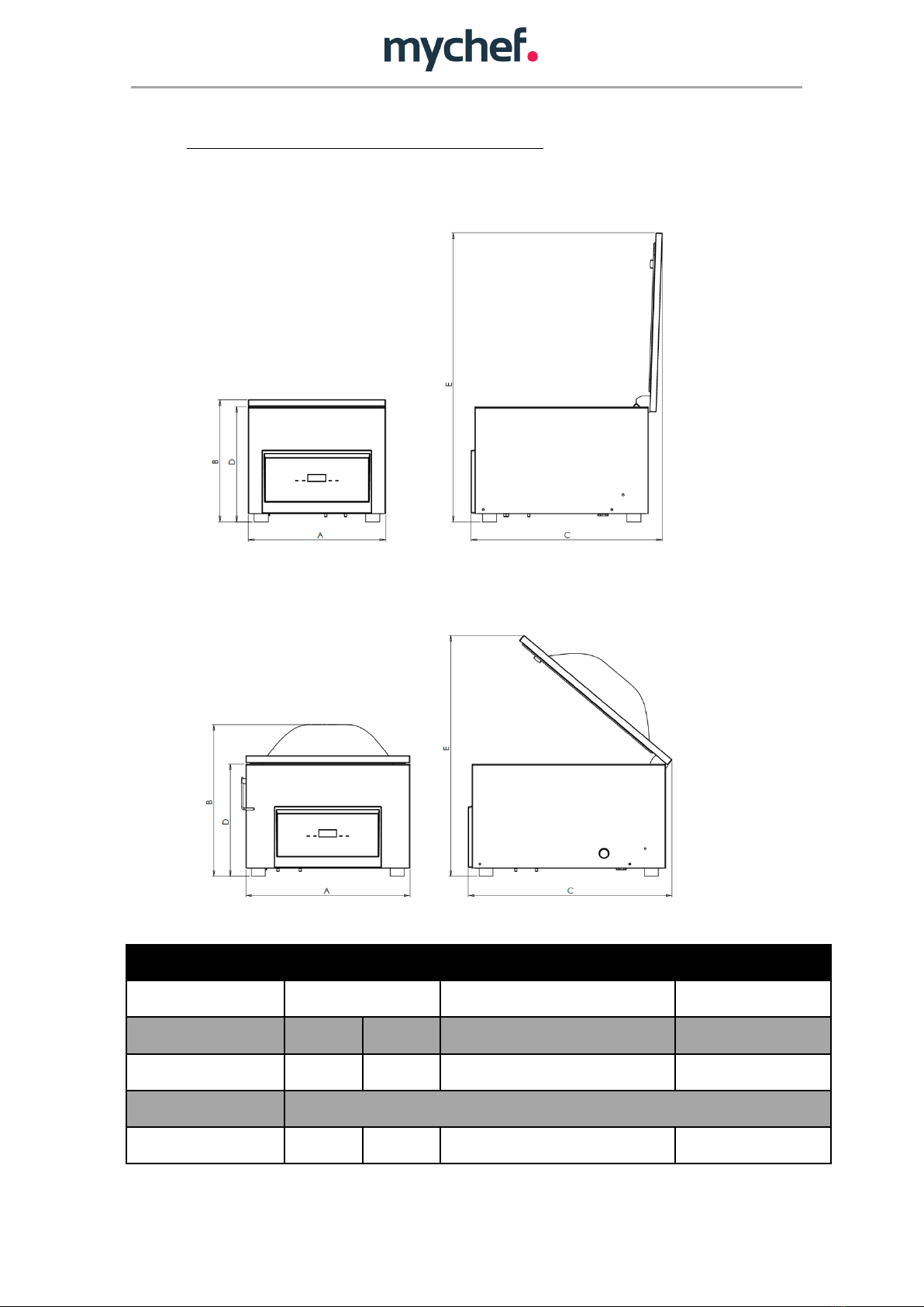
2.3 General measurements of goSensor countertop models...........................................................3
2.4 Vacuum chamber measurements and countertop model goSensor specifications ...................4
3. GENERAL STANDARDS FOR SAFETY AND ACCIDENT PREVENTION......................................................5
3.1 Personnel in charge of the use of the appliance.........................................................................5
3.2 Electrical hazard..........................................................................................................................5
3.3 Thermal hazard ...........................................................................................................................5
4. INSTALLATION......................................................................................................................................6
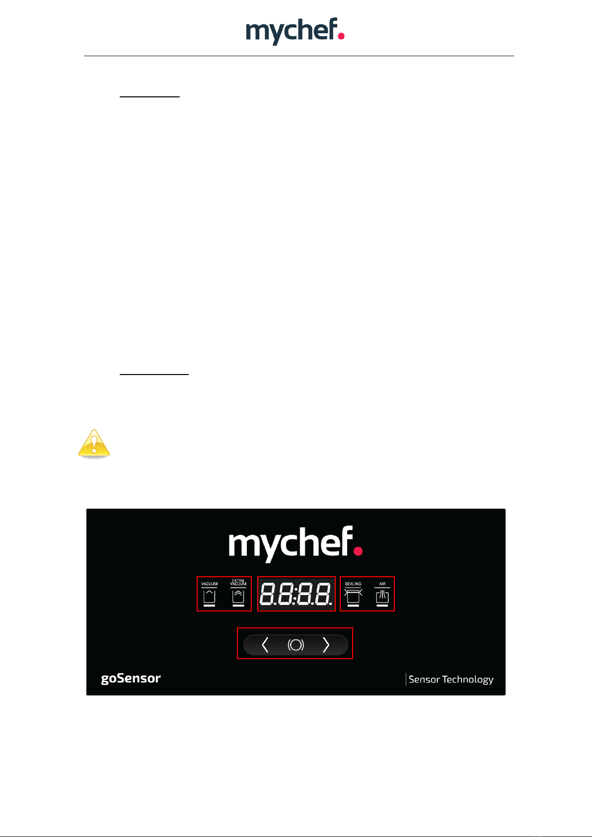
5. CONTROL PANEL ..................................................................................................................................6
6. CALIBRATION .......................................................................................................................................9
6.1 Automatic SCS Calibration ..........................................................................................................9
7. OPERATION........................................................................................................................................10
7.1 Connecting and turning on the appliance.................................................................................10
7.2 Operating modes ......................................................................................................................11
7.2.1 Manual mode: ..................................................................................................................11
7.2.2 Autoclean: ........................................................................................................................13
7.3 Packing ......................................................................................................................................13
8. ERRORS ..............................................................................................................................................15
9. MAINTENANCE ..................................................................................................................................16
9.1 Cleaning ....................................................................................................................................16
9.2 Vacuum pump oil ......................................................................................................................16
9.3 Sealing bar.................................................................................................................................16
9.4 Water-tight seal on the lid ........................................................................................................16
10. MAINTENANCE SCHEDULE ............................................................................................................17
10.1 Check the oil level .....................................................................................................................17
10.2 Change the pump oil.................................................................................................................18
10.2.1 Countertop goSensor .......................................................................................................18
10.3 Other maintenance operations.................................................................................................22
10.4 Owner liability...........................................................................................................................22
11. SPECIFICATIONS.............................................................................................................................23
11.1 General electrical diagram Countertop goSensor SMALL, MEDIUM AND LARGE.....................24
11.2 Pneumatic diagram ...................................................................................................................25

2
1. INTRODUCTION
This document has been prepared in order to provide reliable and helpful information
regarding the use of the appliance. The manufacturer waives all liability, whether express or
implied, for any possible errors or omissions that the manual may contain.
Before operating or using this appliance, read this manual carefully and thoroughly.
The owner of the appliance is responsible for requiring all personnel in charge of use
and maintenance to read this manual.
2. TECHNICAL FEATURES
2.1 Functional equipment
2.2 Design features
•Made of stainless steel.
•Well with rounded edges for easy
cleaning.
•Transparent methacrylate lid to allow for
a view of the product being packed.
•Liquid packing accessory for the various
vacuum packer models.
•Foam for the use of a core probe in
vacuum packed foods.
•Side display for checking the oil level.
•Removable sealing bar without
connections
•Polyethylene plate inside the chamber
that increases the speed of the vacuum
and regulates the working height.
•Progressive pressure restoration to
prevent damage to the bag caused by
bones, etc.
•Sensor-controlled vacuum.
•Self-calibrating system
•All steps of the process are visually
monitored.
•Liquid packing mode.
•Extra vacuum to force air out of porous
products.
•STOP Possibility to block the vacuum
packer for a certain amount of time or for
as long as the user wishes.
•“OIL AUTO-CLEAN” process, oil self-
cleaning system.
•Equipped with interior polyethylene plate

3
2.3 General measurements of goSensor countertop models
Small flat-lid goSensor Model
goSensor Models with dome lids
Table 1. goSensor general dimensions
REFERENCES
TGS8F1E2
TGS8D1E2
TGM101E2
TGM161E2
TGM201E2
TGL201E2
TGL202E2
Dimension A (mm)
388
475
620
Dimension B (mm)
345
389
438
453
Dimension C (mm)
340
519
589
599
Dimension D (mm)
325
Dimension E (mm)
815
650
696
702

4
2.4 Vacuum chamber measurements and countertop model goSensor specifications
REFERENCES
TGS8F1E2
TGS8D1E2
TGM101E2
TGM161E2
TGM201E2
TGL201E2
TGL202E2
Interior chamber dimensions
(mm)
328x385x115
328x385x162
412x453x200
560x465x210
Pump capacity (m3/h)
8
10
16
20
20
Approximate machine cycle
(seconds)
35
40
42
30
28
40
35
Sealing bar length (mm)
315
405
455
455 + 455
Approx. weight (kg)
32
36
47
48,5
55
64
67
Power (kW)
0.350
0.350
0.370
0.55
0.75
0.75
Table 2. goSensor general specifications

5
3. GENERAL STANDARDS FOR SAFETY AND ACCIDENT PREVENTION
3.1 Personnel in charge of the use of the appliance
The use of the appliance is reserved for trained personnel.
Personnel must be familiar with the safety standards and the instructions for use.
3.2 Electrical hazard
Work on the electrical power source and access to live parts is only permitted to skilled
personnel and is under their responsibility. In any case, said access must be carried out
with the appliance disconnected from the electricity grid.
3.3 Thermal hazard
Make sure the ventilation openings are not blocked.
Do not install the appliance near flammable products.

6
4. INSTALLATION
Once the appliance has been received, remove the packaging carefully and check the
equipment against the label (located on the rear-left side) to be sure that this is the requested
appliance. Once the appliance has been checked, read this “Installation, usage and
maintenance manual” bearing in mind the following precautions:
a) The personnel in charge of the installation must be qualified in appliance installation.
b) Verify that the voltage/current source corresponds to that required by the appliance.
c) Grounding is mandatory.
d) Check that the elements that make up the equipment are properly situated and free
from damage from transport.
Place the appliance on a flat surface and ensure that it is level.
The appliance should be placed so that it is protected from splashes of water and dirt.
Before starting up the equipment, check the rear display to see whether the oil level is
between the MAX and MIN markings. If the level is below the minimum, it must be refilled (see
section 10 Maintenance).
5. CONTROL PANEL
The goSensor vacuum packers from Mychef consist of a 4-digit screen with 7 segments, three
push-buttons and four LEDs that indicate the status of the appliance during the packing cycle.
Do not clean the vacuum packer screen cover with alcohol-based liquids, solvents,
acids or detergents as these may damage the cover and affect the display.
These elements are used for checking, viewing and modifying the various packing parameters.
See below for the location and function of these elements.
Figure 1. LCD screen with all segments illuminated
A
A
C
B

7
-Zone A (Figure 1): The LEDs tell you the status of the vacuum packer when you are
carrying out a packing cycle.
-Zone B (Figure 1): Displays the values of the various packing parameters: vacuum %,
seconds, minutes, air restoration mode and errors.
-Zone C (Figure 1): Corresponds to the buttons that allow you to configure the desired
packing parameters and to cancel a cycle if you wish (centre button).
The goSensor vacuum packer is designed to be very simple and easy to use. It has a start menu
and a packing parameter settings menu, an explain of which is set out below.
Start menu
The vacuum packer will be turned on and you will be able to change the operating mode that
you want it to perform with the direction buttons. More specifically, you will have the option
of three modes:
Mode: “Set” Vacuum pack or change vacuum packing parameters
Figure 2. “SET” mode
When the vacuum packer is in “Set” mode, you have two options: The first is to lower the lid
and the vacuum packer will perform a packing cycle with the parameters saved in the memory.
The second option is to press the centre button and to set the packing parameters according
to the client’s wishes (explained in section 7.2).
Mode: “Clean” Carry out a pump oil cleaning cycle
Figure 3. “CLEAN” mode
In this mode you just have to lower the lid and the vacuum packer will perform an oil cleaning
cycle.

8
Mode: “Off” Turn off the vacuum packer
Figure 4. “OFF” mode
In this mode the vacuum packer will turn off automatically after a few seconds. If you wish to
turn it off immediately, you will need to press the centre button.
Vacuum packing settings menu
To access this menu, you will need to press the centre button when the vacuum packer is in
the “SET” mode in the start menu. In this menu you can configure the following packing
parameters:
•Vacuum percentage (Vacuum).
•Extra Vacuum time (Extra Vacuum). You will only be able to configure this option by
selecting a vacuum percentage of 100%.
•Sealing time in seconds (Seal).
•Atmospheric pressure restoration mode (Air), where you can select three modes:
oFAST: fast restoration.
oSOFT: slow restoration for delicate foods/objects.
oSTOP: block the vacuum chamber with the selected vacuum percentage. A
time (minutes) can be set, or until the user presses the centre button. For this
option, the user must not set any STOP time.
For more detailed information, see section 7.

9
6. CALIBRATION
6.1 Automatic SCS Calibration
goSensor countertop sensor vacuum packers have a fully automatic calibration system, Self
Calibration System (SCS), patented by Mychef. This automatic vacuum percentage
recalibration algorithm has the following advantages:
•Calibration without user intervention
The appliance automatically detects optimal calibration conditions and, completely
autonomously, can recalibrate itself according to the following physical changes:
•Automatic adaptation to temperature variations.
•Automatic adaptation to climate variations.
•Automatic adaptation to altitude variations.
•Automatic adaptation to variation in oil properties.
The appliance is able to detect increases and decreases in differential atmospheric
pressure, recalibrating itself as needed.
•Increased precision in measuring the vacuum.
By constantly calibrating itself automatically, the values used to calculate the vacuum
percentage are dynamically updated. Therefore, the vacuum percentage that the user selects
has a smaller error margin than if it were to not dynamically calibrated.

10
7. OPERATION
7.1 Connecting and turning on the appliance
When the appliance is connected to the electricity grid, a start-up process takes place where
all internal values are initialised and safety and control checks are carried out to ensure
optimum control of the vacuum packing. This process will be indicated on the screen by the
simultaneous flashing of all segments for a number of seconds.
While the segments are flashing, you can check the technical control parameters by pressing
the centre button. These parameters may be relevant for the maintenance of the appliance.
Two parameters will be displayed:
- Vacuum pump operating hours.
- Number of vacuum cycles completed.
The first value displayed will be the vacuum pump operating hours. The number digits will be
displayed on the 7-segment screen in a cyclical manner, with the end of the cycle being
indicated by “Hour”. For example, if the pump motor has been operational for 20991 hours,
the screen will display “2 – 0 –9 –9 –1 –Hour ” on a loop.
Figure 5. Vacuum pump operating hours view
Pressing the centre button while the number of pump operating hours is being displayed will
show the number of vacuum cycles completed by the vacuum packer. The value will be
displayed in the same way as above, but instead of “Hour” indicating the end of the number of
operating hours, the screen will show “Cycl” to represent the vacuum packing cycles.
Figure 6. Vacuum cycles completed view
To stop showing this value and to finalise the appliance start-up process, press the centre
button again.

11
Once the vacuum packer is connected to the electricity grid and the start-up process is
finalised (whether the pump status values are checked or not), the appliance will turn itself off.
The user is required to turn the appliance on in order to begin operating.
The appliance can be turned on in three different ways:
- Pressing any of the three buttons.
Any interaction will start up the appliance.
DANGER! The Manufacturer waives any liability for injuries to people or animals and
damages to the elements resulting from improper, non-compliant use of the
appliance.
7.2 Operating modes
goSensor vacuum packers have three different operating modes: the “SET” mode; the self-
cleaning “CLN” mode; and the “OFF” mode. The operating mode is selected by pressing the
direction buttons (right and left) until the desired text is displayed on the 7-segment screen.
7.2.1 Manual mode:
The manual mode (“Set” on the vacuum packer screen) gives the user exhaustive control over
the packing parameters and allows the user to access some special features, such as extra
sealing time, extra vacuum time and atmospheric pressure restoration type.
Figure 7. Manual mode.
Selecting the “SET” icon allows you to set the packing parameters for a specific purpose, such
as making marinades or vacuum packing products with bones that may damage the bag.
The parameters entered do not need to be modified or entered every time because the
vacuum packer stores them. You only need to modify them when you want to perform a cycle
with different parameters.
To modify the parameter values, press the centre button. The LED corresponding to the icon
for the parameter that is to be changed will light up. For example, if the sealing time is to be
changed, the LED corresponding to the “SEAL” icon will be illuminated. The direction buttons
(right and left) can then be used to modify the parameter value. The parameter is saved by
pressing it again and you jump to the next value to configure. This process is repeated until all
the parameters are modified and saved and you return to the start point of the “SET” manual
mode.

12
Figure 8. Modifying the packing parameters in manual mode
All parameters are described below in the order of configuration:
- Vacuum percentage:
This parameter sets a vacuum value expressed as a percentage. Once the pump reaches
this value, it will disconnect and it will proceed to the next step. The goSensor vacuum
packer also has a liquid packing program that will appear after 100% vacuum, and it will be
indicated on the display by “H2O”. This parameter is represented by the “VACUUM” icon.
- Extra vacuum packing time:
Extra vacuum packing time sets a time in seconds during which the vacuum pump remains
turned on. This extra time is used to ensure the proper vacuum packing of very porous
foods. To operate correctly, this time can only be set when 100% vacuum is selected. This
parameter is represented by the “EXTRA VACUUM” icon.
- Sealing time:
This value specifies the bag sealing time. It sets the duration of electrical contact with the
sealing bars and it must be adjusted for each bag type. In order to know the right amount
of time, it is advisable to consult the bag supplier. This parameter is represented by the
“SEALING” icon.
- Atmospheric pressure restoration mode:
This parameter allows for the selection of 3 types of air entry:
1. FAST: The restoration of atmospheric pressure in FAST mode allows air to enter
suddenly through the opening of an entry valve until atmospheric pressure is restored
inside the chamber. It is the fastest and most appropriate mode in most cases.
2. SOFT: Pressure restoration in SOFT mode allows for the entry of air in an intermittent
manner, thus controlling any deformations that may occur to the bag. This mode is
useful for the slow restoration of atmospheric pressure, so that the packed food
moulds correctly to the bag and prevents sharp or pointy elements from breaking it.
3. STOP: This mode makes it possible to stop the pump at a certain vacuum value by
pressing the centre button or until the value determined by the vacuum percentage is
reached. The vacuum packer will maintain this vacuum until the set time limit has
passed or, if no time limit has been set, until the user presses the centre button. This
process may be useful for marinating meats or fish or to extract air from sauces.

13
This parameter is identified by the “AIR” icon and each type of restoration is selected using
the icons located below: “FAST”, “SOFT” and “STOP”.
7.2.2 Autoclean:
When the vacuum pump’s oil has taken on a whitish shade, due to water condensation, it can
be removed using this mode. Due to the temperature, this process means any water that may
be in the oil will end up evaporating and exiting the pump.
These water particles may cause rust particles to develop on internal components of the
pump.
➔The vacuum packer will notify the user of the need to perform a self-cleaning process after
every 200 cycles. This will happen when the appliance is connected to the electricity grid
or it is turned on from the “OFF” rest mode. If the lid is lowered during this time, the
“AUTOCLEAN OIL” process will begin automatically.
If you do not wish to perform the AUTOCLEAN process when the notification appears, you
can press the direction buttons (right and left) to go through the menu as normal and
perform the cycle you prefer.
You can run an AUTOCLEAN cycle whenever you wish by manually entering AUTOCLEAN mode
from the operating mode selection menu. The maximum duration of AUTO-CLEAN mode is 10
minutes, although you can stop it by pressing the centre button.
7.3 Packing
To pack a product, the bag (appropriate for vacuum packing) must be placed correctly on the
polyethylene bar with the entire width of the bag above the sealing area. Make sure that there
is no product on the sealing bar. Then lower the lid of the vacuum packer. It is important to
remember that a packing process may begin while you are configuring the manual mode
parameters.
NOTE: We recommend using the safety latch during each vacuum packing cycle.
At this time, the stored program begins, and the indicators of the processes to be carried out
will light up continuously (vacuum, extra vacuum, sealing, progressive air entry):
- The vacuum process (VACUUM) extracts the air from the chamber and the central
display shows the vacuum percentage up to that moment.
- The extra vacuum procedure (EXTRA VACUUM) keeps the vacuum pump working for
the number of seconds programmed. This extracts the air from very porous foods. The
central display shows the number of seconds passed.
- Sealing consists of three phases. The first is the lifting of the cylinders. During this
phase, the centre screen displays the set sealing time in seconds. The second is the
heating of the heating element. At this stage the SEAL display will progressively
decrease from the previous value. The third stage, with a duration of five seconds, is

14
the cooling of the bag, and the SEAL display increases progressively to 5.0 s at this
stage.
- The last stage is the restoration of atmospheric pressure (AIR). The display will show
the vacuum percentage in the chamber decreasing. The atmospheric pressure
restoration type (SOFT, FAST or STOP) will also be illuminated during this stage.
The associated indicator will turn on to signal which process is active. Once the process has
finished, the indicator will turn off.
All processes, with the exception of vacuum chamber pressure restoration, can be cancelled by
pressing the centre button while they are running. By doing so, the appliance will progress to
the next step in the cycle until the air entry stage, at which point the cycle will end.
If the vacuum is not correctly completed, an error will be displayed (see 8).
A rest period of 3 minutes between cycles is recommended.

15
8. ERRORS
The device uses algorithms that detect abnormal situations which could lead to
malfunctioning. The user is notified of these situations with an error screen such as the one
shown below:
Figure 9. Error screen
The table below shows the errors and possible solutions:
Error
Description
Solution
E01
Lowered lid
Open the lid. If the error persists, call the technical service, indicating the error
code.
E02
Error in the vacuum system
The system has detected that the vacuum pump has operated too long to reach
a certain vacuum level. Calibrate the system. If the calibration is carried out
successfully, conduct the test again. Otherwise, call the technical service. The
maximum operating time is 2 minutes.
E03
Error in the vacuum sensor
(minimum)
Check the vacuum sensor connection tube for leaks or a poor connection. If
everything seems correct, call the technical service indicating the error code
and the central display value right before the error.
E04
Error in the vacuum sensor
(maximum)
Check the vacuum sensor connection tube for leaks or a poor connection. If
everything seems correct, call the technical service indicating the error code
and the central display indicator value right before the error.
E05
Internal error
The control board has detected an internal error. Call the technical service,
indicating the error code.
Table 3. Errors and possible solutions
The appliance runs automatic checks and, as a result, it may turn itself off to prevent a serious
error. Turn it on as usual.
In the event of an error with the vacuum packer, please contact the technical
service.

16
9. MAINTENANCE
Before the appliance is handled for cleaning, maintenance or repair, it should be
disconnected from the electricity grid.
If the power line is damaged, it should be replaced by the manufacturer, its after-
sales service or by personnel with similar qualifications in order to avoid danger.
9.1 Cleaning
Clean the vacuum packer regularly and carefully.
Cleaning the vacuum packer with pressure cleaning equipment is HARMFUL to the
appliance and may cause the appliance to break, and it will void the WARRANTY.
To clean the stainless-steel outer casing, use a damp cloth with water and detergent.
The lid must be cleaned with a damp cloth soaked in water; chemical products must
not be used.
DO NOT USE ANY TYPE OF LIQUID WHICH CONTAINS ALCOHOL, ACID, DETERGENTS,
SOLVENTS OR EQUIVALENT TO CLEAN THE LID.
Failure to comply with these instructions may break the lid and void its warranty.
9.2 Vacuum pump oil
Periodically check the oil level, topping up where necessary, according to the maximum and
minimum levels.
Use the type of oil recommended by the vacuum pump manufacturer (depending on the
model).
Oil in a good condition will be transparent. If it turns white, this means that it has taken on
water from the condensation of the damp vacuumed air which would entail that it has lost its
characteristics and must be replaced.
The oil may also take on a dark colour due to vacuumed dirt, which would entail that it has lost
its properties and must be replaced.
The vacuum pump used by this appliance is not prepared for working in extremely hot/cold
environments. Operating temperature range is 12-35ºC.
9.3 Sealing bar
Periodically check the condition of the Teflon adhesive tape and the sealing tape. They must be
in perfect condition and not have any defects.
9.4 Water-tight seal on the lid
Periodically check the condition of the water-tight seal on the lid. It must be in perfect
condition.

17
10. MAINTENANCE SCHEDULE
First 100 operating hours
Change the oil
Weekly or when the “CLN” message appears
on the vacuum packer
Carry out an auto-clean program
Check the oil level
Check the condition of the sealing bar
Check the condition of the water-tight seal
Weekly or every 500 hours of operation
Change the oil
Every 1000 hours of operation
Change the oil filter
Annually
Check for possible leaks in the vacuum circuit
Table 4. Check schedule
It is recommended that maintenance be carried out by a qualified professional,
your distributor, or the technical service.
10.1 Check the oil level
To check the pump’s oil level it is not necessary to open the vacuum packer; there is a
viewing hole on one of the two sides for this purpose.
Figure 1. Rear display for checking the oil level

18
10.2 Change the pump oil
Material needed for the oil change:
•Material: Synthetic oil SAE 10 VSL32 (countertop models)
Figure 2. Oil replacement kit
•Tools:
oNumber 3 Allen wrench.
oAdjustable wrench
Warning: Before removing any components, verify that the appliance is disconnected
from the electricity grid and the water supply.
10.2.1 Countertop goSensor
Step 1→Remove the two rear screws
Using the number 3 Allen wrench, remove the two rear screws on the sides (do not remove the front
screws because the well pivots on them). After removing these two screws, use the same Allen wrench
to loosen the centre screw on the rear (it is not necessary to remove it completely).

19
Step 2 →Open the outer casing of the vacuum packer
As with the hood of a car, lift the back of the vacuum packer until its limit.
Figure 4. Open the outer casing
Step 3 →Open the plug to empty the pump
Using an adjustable wrench, remove the plug to drain the oil from the pump.
Figure 3. Rear screws
Rear side section
This manual suits for next models
6
Table of contents
Other Mychef Kitchen Appliance manuals

Mychef
Mychef MYCHA263 User manual

Mychef
Mychef Mychef Cook Pro 4 GN 1/1 User manual

Mychef
Mychef Cook User manual

Mychef
Mychef iSENSOR FSS Series User manual

Mychef
Mychef SNACK User manual

Mychef
Mychef Bake User manual

Mychef
Mychef SNACK User manual

Mychef
Mychef COMPACT EVOLUTION Series User manual

Mychef
Mychef iSENSOR User manual

Mychef
Mychef iSENSOR FSSB4 G2 Series User manual