LBI-38936
6
DESCRIPTION
Ericsson GE Vehicular Charger/Repeater units
344A4616P1 (Part 1) and 344A4616P2 (Part 2) provide a
mobile charging capability for either the M-RK I or M-
RK II personal hand held radios. These charger/repeater
units operate with either the standard high capacity
(19A149838P1 - 1200 mAh), or the extra high capacity
(344A3278P1 - 1700 mAh) nickel-cadmium battery
packs. The personal radio battery pack has a charging
current applied whenever the radio is inserted into the
charging sleeve. An enable/disable function is included
for the Part 1 (Vehicular Repeater System) charger.
With the Part 1 charger, the Vehicular Repeater
System is active only when the M-RK radio is not in the
charging sleeve. When the M-RK is out of the charging
sleeve only then can the M-RK transmitted signal be
routed through the repeater. Inserting the radio into the
charging sleeve switches off the repeater.
With the radio out of the charging sleeve, the repeater
enable switch must also be in the enable position for
repeater operation. This switch is part of the repeater
receiver. When it is in the on position the RED LED
labeled
RPT lights.
When a radio is inserted into the charger, charging
contacts are automatically made at the back of the radio.
A radio detect microswitch (S1), located near the charging
contacts, applies power and the fast charge begins,
provided the battery is in the acceptable temperature
range. A second microswitch determines the charging rate
required based upon battery size.
The High/Low temperature limit detector circuit
measures battery pack temperature by monitoring the
resistance of the battery thermistor. It provides a signal to
the charge microprocessor if the battery is within
acceptable temperature limits for fast charging.
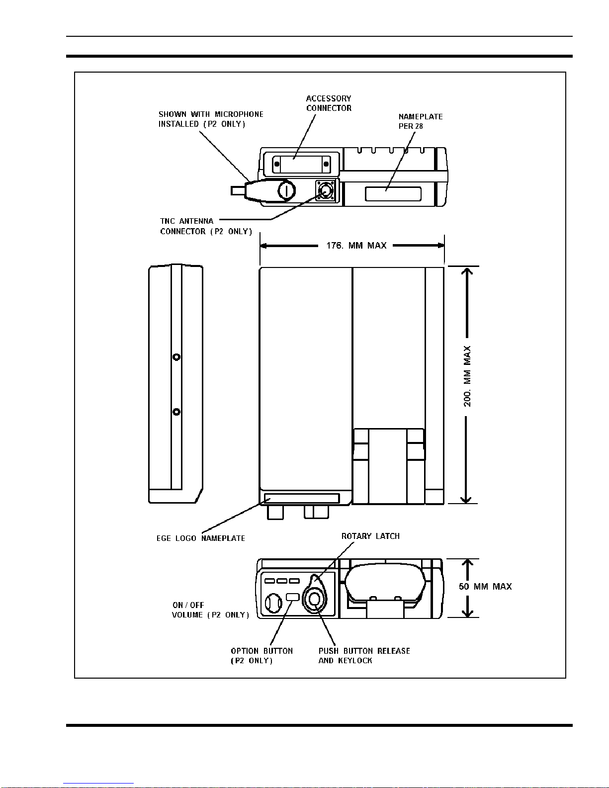
The radio can be operated while in a Part 2 charger.
Provision for this operation is designed into the charger
with a vehicular antenna and a remote microphone
connected at the bottom of the charger (Refer to Figure
1B). The connections to the radio required for this
operation are made through the Universal Devices
Connector
(UDC) when the radio is inserted in the
charger by turning the front panel rotary latch knob
clockwise to the locking position. In this position the
UDC contacts meet with mating contacts on the M-RK I
or II personal radio for operation and the radio is locked
into the charger. Pushing a release button on the top of the
rotary latch knob releases and disconnects the radio from
operation. This release button arrangement is supplied
with a key that can be used to lock the push-button in the
clockwise (locked) position. With the lock engaged, the
release cannot be pressed. This locks the radio to the
charger and it cannot be removed.
STANDARD VEHICULAR CHARGER
(344A4616P1)
The front panel of this charger contains three (3)
indicator lights; RPT, RDY, and CHRG, an ON/OFF
switch for the Repeater Radio and the UDC ROTARY
LATCH KNOB (Refer to Figure 1A and 1B).
(1) Indicator Lights:
RPT (Red) - Lights if the Repeater Radio is
powered ON.
RDY (Green) - Lights if the Battery is 90 to 100
percent charged and the charger reverts to "trickle"
charge.
CHRG (Yellow) - Lights when radio is first
inserted in the charger. Indicates Radio is being
"fast" charged.
(2) Repeater ON/OFF switch:
Turning this switch ON any time the M-RK
personal radio is out of the charger powers the
repeater radio and lights the Red Indicator light.
(3) UDC Rotary Latch Knob:
This knob latches the M-RK personal radio in the
charger and only secures the radio into the charger.
When the latch is activated, no other electrical
connections are made to the radio. It should always
be latched when the radio is in the charger and the
vehicle is moving.
ENHANCED VEHICULAR CHARGER
(344A4616P2)
The front panel of this charger contains three (3)
indicator lights; TX, RDY, and CHRG, an ON/OFF
volume control switch for operation of the M-RK personal
radio as a mobile radio, an option push-button, and the
UDC ROTARY LATCH KNOB (Refer to Figure 1A).
(1) Indicator Lights:
TX (Red) - Lights if the M-RK transmitter is
active.
RDY (Green) - Lights if the Battery is 90 to 100
percent charged and the charger reverts to "trickle"
charge.
CHRG (Yellow) Lights when radio is first inserted
in the charger. Indicates Radio is being "fast"
charged.
(2) ON/OFF Volume Control Switch: