Myenergi zappi Series User manual

Manual
MODELS:
ZAPPI-207UW ZAPPI-207UB
ZAPPI-207TW ZAPPI-207TB
ZAPPI-222UW ZAPPI-222TW
ZAPPI-222UB ZAPPI-222TB
Rev 1.3 September 2019 – ENGLISH

ContentsIntroduction....................................................................................................................................3Safety............................................................................................................................................................................................3
Box Contents...............................................................................................................................4Overview......................................................................................................................................................................................4
Operation.......................................................................................................................................6Controls & Indicators...............................................................................................................................................................6
Display..........................................................................................................................................................................................7
Status Screens...........................................................................................................................................................................9
Charging Modes........................................................................................................................................................................11
Manual Boost............................................................................................................................................................................12
Smart Boost..............................................................................................................................................................................12
Boost Timer...............................................................................................................................................................................14
Lock Function...........................................................................................................................................................................15
Menus..............................................................................................................................................16Main Menu..................................................................................................................................................................................16
Advanced Menu........................................................................................................................................................................19
Advanced Settings.................................................................................................................20eSense.......................................................................................................................................................................................23
Linking Devices.......................................................................................................................................................................24
Installation....................................................................................................................................27Electrical Installation.............................................................................................................................................................29
Wiring.........................................................................................................................................................................................30
eSense Input (economy tariff).............................................................................................................................................31
Fitting the Cover.....................................................................................................................................................................36
Advanced Installation Options............................................................................................................................................37
Built-in Protection......................................................................................................................39RCD Protection........................................................................................................................................................................39
Loss of PEN Conductor.........................................................................................................................................................39
Loss of PE..................................................................................................................................................................................39
Welded Contact.......................................................................................................................................................................39
Over-current............................................................................................................................................................................39
Over and Under-voltage.......................................................................................................................................................40
Thermal Limit..........................................................................................................................................................................40
Setup..............................................................................................................................................40Troubleshooting........................................................................................................................41Faults..........................................................................................................................................................................................42
Warranty.......................................................................................................................................43Product Registration...............................................................................................................43Technical Specifications.....................................................................................................44The myenergi app..................................................................................................................46The myenergi forum..............................................................................................................46Technical Support...................................................................................................................46b Eco-Smart Energy Diverter............................................................................................46My Devices.................................................................................................................................472zappioperation and installation manual

IntroductionIntroductionThank you for choosing zappi. Of course, we think you have made an excellent choice and are sure you will be very
happy with the features, benefits and quality of this myenergi product.
These instructions will help you to familiarise yourself with the zappi, by reading the instructions, you will be sure to
get the maximum benefit from this 'eco-smart' device.
Safetyzappi is an AC EV charger, intended to be installed in a fixed location and permanently connected to the AC supply
network. It is a Class 1 item of electrical equipment in accordance with IEC 61140.
The unit is designed for indoor or outdoor use at a location with restricted access and should be mounted vertically
either surface (wall) mounted or on the dedicated pole mount supplied separately by myenergi.
The device has been manufactured in accordance with the state of the art and the recognised safety standards.
However, incorrect operation or misuse may result in:
Injury or death to the operator or third parties
Damage to the device and other property of the operator
Inefficient operation of the device
All persons involved in commissioning, maintaining and servicing the device must:
Be suitably qualified
Have knowledge of and experience in dealing with electrical installations
Read and follow these operating instructions carefully
Always disconnect the device from the supply before removing the cover
The device is not to be used by persons (including children) with reduced physical, sensory or mental capabilities, or
lack of experience and knowledge, unless they have been given supervision or instruction concerning use of the
device by a person responsible for their safety.
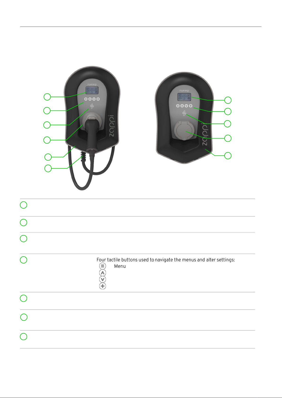
zappi comes in either tethered or untethered variants. The untethered version should only be used with a
dedicated Type 2 cable which is compliant with EN 62196-1 and EN 62196-2. Adapters, extension cables and
conversation cables must not be used with either version of the zappi.
Failure to install and operate the zappi in accordance with these instructions may damage the unit and invalidate
the manufacturer’s warranty.
DisposalIn accordance with European Directive 2002/96/EC on waste electrical and electronic equipment and its
implementation in national law, used electrical devices must be collected separately and recycled in an
environmentally responsible manner. Ensure that you return your used device to your dealer or obtain information
regarding a local, authorised collection and disposal system. Failure to comply with this EU Directive may result in a
negative impact on the environment.
CopyrightCopyright of these operating instructions remains with the manufacturer. Text and images correspond to the
technical level at the time of going to press. We reserve the right to make changes. The content of the operating
instructions shall not give rise to any claims on the part of the purchaser. We are grateful for any suggestions for
improvement and notices of errors in the operating instructions.
myenergi zappi, myenergi eddi, myenergi harvi and myenergi hub are registered trademarks of myenergi Ltd.
operation and installation manual zappi3

Box ContentsBox ContentsTethered units Untethered units
1 x zappi unit with EV cable and connector attached.
1 x Cable wall guard
1 or 3 x CT Clamps
(1 x single phase units / 3 x three-phase units).
1 x Mounting template.
1 x Mounting kit for a brick wall.
1 x zappi unit.
1 or 3 x CT Clamps
(1 x single phase units / 3 x three-phase units).
1 x Mounting template.
1 x Mounting kit for a brick wall.
Mounting kit (Tethered units) Mounting kit (Untethered units)
4 x 50mm Pozi screws
4 x Wall mounting plug
4 x Sealing washer
4 x 12mm Pozi screws (countersunk)
4 x 50mm Pozi screws
4 x Wall mounting plug
4 x Sealing washer
OverviewMicrogeneration systems such as Solar PV and small wind turbines are at their most efficient when the generated
energy is consumed on-site rather than exporting it to the grid. This is what we call 'self-consumption'.
zappi is a Mode 3 charging station, compatible with all electric vehicles that comply with EN 62196 and EN 61851-1
plug-in electric vehicle standards.
zappi works like any regular charging point but has special ECO charging modes that will benefit homeowners with
grid-tied microgeneration systems e.g. wind or solar generation. Two special ECO charging modes automatically
adjust charging current in response to on-site generation and household power consumption. In FAST charge mode,
zappi operates like an ordinary EV charger.
A grid current sensor (supplied) simply clips around the incoming supply cable. this sensor is used to monitor excess
power and when using the special ECO charge modes, zappi will automatically adjust the charge rate in response to
available surplus.
Feature Set•3 charging modes: ECO, ECO+ & FAST
•Optimises microgeneration self-consumption
•Works with solar PV, wind turbine or micro-hydro systems
•Economy tariff sense input
•Programmable timer function
•Charge and event logging
•Remote control and monitoring add-on option
•Pin-code lock function
•Tap operated display backlight
•Built-in 30mA Type A RCD protection (EN 61008) + 6mA DC RCD protection (EN 62955)
•Built in protection against the loss of the protective neutral and earth (PEN) conductor as required by BS
7671:2018 (The “Wiring Regulations”)
•Integral cable holster (tethered units)
•Supplied with 1 x clip-on grid current sensor (x 3 if purchasing a 3 phase unit)
•Illuminated display – for convenience the display can be illuminated by simply tapping the zappi front cover
Overview DiagramThe diagram opposite, shows the zappi as part of a complete energy management system. Other myenergiproducts are shown and how they integrate with the grid connection and the microgeneration system.
4zappioperation and installation manual

Box Contentsoperation and installation manual zappi5
PV ARRAY
INVERTER
HOT WATER
CYLINDER
SUPPLY
GRID
ELECTRICITY
METER
CONSUMER
UNIT
FiT
METER
Clip-on sensor
with opon of
wired or
wireless
zappi
Features special ECO
charge modes to
manage EV charging
with surplus power
from microgeneraon
varisine™
Technology ensures loads
are supplied by a clean AC
sine wave – only the
voltage is varied
harvi
Harvests power from the
sensor and transmits the
import/export
informaon to the load
controlling devices -
Wiring or baeries not
required
!eddi
Connually adjusts the
power to the heater
elements, making full
use of surplus green
energy without
imporng from the grid
Overview Diagram
Internet router
hub
Communicates with
other myenergi
devices and enables
use of mobile app

OperationOperationControls & IndicatorsDisplay Graphical LCD display with LED backlight
•Backlight can be activated by tapping the unit.
Front fascia Removable fascia for installing and servicing.
Tethered Charging Cable if
applicable 6.5 meter cable with a Type 2 plug or Type 2 socket with locking system
for non tethered models.
Control Buttons
Change charge mode | Move up a menu item | Increase value.
Change charge mode | Move down a menu item | Decrease value.
Boost | Select item | Confirm value and move to next setting.
Integrated Cable Holster
(tethered units only) When not in use, the charging cable should be wrapped around the unit’s
cable holster (tethered units).
Charging Connection Point
(non tethered units) When cable not use, the charging cable should be unplugged and stored in
a cool dry place.
RGB Indicator Visual Indicator that changes colour dependant on the
zappi's
charging
state. (see RGB Indicator page 8)
6zappioperation and installation manual
1
4
5
2
3
11
4
4
2
2
3
56
6
77
7

OperationDisplayImport / Export Power The power being either imported or exported from or to the grid (kW). The
direction of the arrows indicate if the property is currently importing power
(left) or exporting power (right)
The size of the arrows is proportionate to the level of power being
imported / exported, When the property is neither importing or exporting
power the figure will be 0.0kW and there will no animated arrows. The
property is then said to be 'in balance'
House Load Power The power that the property is currently using in kW
Note: This is displayed only when the Generation Sensor is installed directly to a CT input or a
harvi
or other
myenergi
device)
Status Text The current status is displayed here (see Status Screens page 9)
Generation Power The power being generated at this time in kW.
Note: This is displayed only when the CT'S are installed either hard wired to the CT inputs of the
zappi
or wirelessly to a
harvi
or other
myenergi
device)
Lock Icon Operation lock is active.
Date & Time The current date and time.
Mode Icons These icons indicate that the import limiting is active (house) or the e-
Sense input is live (e) see page 22
zappi Icon If you see wavy lines above the
zappi
icon, the unit is thermally limiting!
The output power is temporarily reduced.
Charge Mode Shows the selected Charging Mode; FAST, ECO or ECO+ (see Charging
Modes page 11)
Charge Delivered to EV The accumulated charge energy that has been sent to EV in this charge
session.
Current Charging Power When the EV is charging, arrows will show here along with the charging
power in kW
Green Level of last charge This is percentage of 'Green' energy for the last charge session, this is
shown at the end of a charge or when the EV is unplugged
operation and installation manual zappi7
4
2
1
11
6
7
5
10
98
12
3
1
2
3
4
6
7
8
9
12
10
5
11

OperationDisplay Icons KeyHouse Consumption – Not Importing Charge Mode = FAST
House Consumption – Importing Charge Mode = ECO
Solar Generation Power Charge Mode = ECO+
Wind Generation Power zappi Device – Normal
On the three phase zappi the number in the
icon indicates whether the EV is charging
with a single phase or all three phases.
Grid Power – Import / Export zappi Device – Too Warm (output limited)
Number indicates single or three phase
charging
Power Flow Direction – Small Amount Import Power Limiting Active
Power Flow Direction – Medium Amount Economy Tariff Electricity Available
Power Flow Direction – Large Amount Current Charging Power
Waiting For Surplus Power Energy sent to EV for this charge
DSR Mode (demand side response) 1Warning – refer to text on screen
Lock icon – Zappi or cable locked
(untethered versions only)
RGB Indicator The lightning flash indicator on the front of the zappi indicates the status of the charge:
Pink: Connected
Green: Charging 100% Green
White: Charging from Grid Only
Yellow: Charging mix of grid/green energy
Blue: Charge complete
Red: Error
The colour effect (variation of the brightness) speeds up according to the charging power.
1 DSR – Demand Side Response – A smart feature for future use by electricity suppliers and distribution
companies to help manage load on the electricity system at times of high demand. This feature can only be
enabled by the owner of the zappi.8zappioperation and installation manual
3
3

OperationStatus ScreensEV DisconnectedThe EV is not connected to zappiIn this example the last charging session delivered 20.8kWh of
energy to the EV and 80% of that energy came from the solar
panels.
Waiting for Surplus...zappi is waiting for sufficient surplus power from the
microgeneration system. This screen will be shown in ECO+ mode
as it's only in this mode that charging will stop if there is not
enough surplus power.
The house in the centre is straight-faced as grid electricity is being
used by the house (0.9kW is this example).
Surplus...Enough surplus is available and zappi is about to charge the EV. A
timer is decremented and can be set in the charge settings (ECO+
mode only).
Waiting for EV...zappi is waiting for the EV to respond; the EV is not ready to
accept charge.
Charge DelayedThe charging session has been delayed by the EV because a
scheduled charge has been set in the vehicle.
Paused...zappi is paused for a few seconds in order to limit the start/stop
frequency during ECO+ mode charging.
operation and installation manual zappi9

OperationChargingThe EV is charging.
In this example the car is charging in ECO+ mode at 1.6kW, there is
no import or export from the grid (0.0kW) and the EV battery has
charged by 8.9kWh since the car started.
Charge CompleteThe EV is fully charged.
The charge energy used during the last charge is displayed at the
bottom right (20.0kWh in this case) and the 'green contribution' is
also shown (40% in this example).
Restart...zappi is doing a restart sequence.
This may happen with some EVs that need to be 'woken-up' to start
charging after a pause in the charge. Charge should start
immediately afterwards, otherwise the “Charge Delayed” message
will appear.
…StoppingZappi is about to stop the EV charging
Checking...zappi is carrying out a check to make sure that the built in RCD and
“PEN Fault” protection is working before starting to charge the car.
zappi carries out this before every charge so there is no need to
manually test the RCD protection.
10 zappioperation and installation manual

OperationCharging Modeszappi has three different charging modes which can be selected simply by pressing the buttons when
the main screen is showing. The charge mode can be changed before or during a charge.
Regardless of the charge mode used, all of the surplus electricity is used but zappi's special eco charge modes
limit the amount of grid electric used. Below is explanation of each of the three charging modes.
Charges at the fastest rate.
Fast Mode will charge the EV at the fastest rate and will import grid electricity if there is insufficient surplus
generated power.
The actual charge rate is dependant on the EV's onboard charger and the grid supply voltage although some
vehicles can charge at 11kW or 22kW on a 3-Phase zappi, many EV's have lower charge rates, the maximum
charge rate for the single phase zappi is 7kW.
The actual power can vary if the grid supply voltage is not exactly 230V.
Adjusts the charge rate to limit the use of grid electricity.
The charge rate is continuously adjusted, in response to changes in generation or power consumption
elsewhere in the home, thereby minimising the use of grid power.
Charging will continue until the vehicle is fully charged, using available surplus power.
However, if at any time, the available surplus power falls below 1.4kW, the shortfall will be drawn from the grid.
Note: The EV charging standard does not support charging below 1.4kW.
Adjusts the charge rate to limit the use of grid electricity and will pause the
charge if there is too much or any grid electricity being used (setup dependant)
The charge rate is continuously adjusted, in response to changes in generation or power consumption
elsewhere in the home, thereby minimising the use of grid power. Charging will pause if there is too much
imported power, continuing only when there is enough surplus power available. The surplus power threshold
at which the charge will start or stop can be set using Min Green Level in the ECO+ Settings of the
Charge Settings menu.
The actual green contribution percentage is shown when the charge is complete or when the zappi has been
disconnected from the EV.
It is possible to charge the EV using only surplus renewable power, providing there is sufficient surplus power
available and a boost option has not been set. (Please note: The EV charging standard does not support
charging below 1.4kW)
example: when
zappi
is set to a Min Green Level of 100% you will need in excess of 1.4kw (approx) of surplus
energy available to start the charge, if the surplus falls below the 1.4kw threshold the charge will pause until the
threshold is once again met, after a short delay
zappi
will resume charge.
You can if preferable set the
zappi
to share power from the grid and generation source to ensure a charge is
always maintained, e.g. Min Green Level could be set to 75% (using mostly surplus but will use a little grid if
needed).
operation and installation manual zappi11

OperationManual BoostThe Manual Boost function can only be used when charging in ECO or ECO+ mode. When boosting, the charge rate is
set to maximum (just like FAST mode), until a set amount of energy has been stored in the EV's battery. After which,
zappi will revert back to ECO or ECO+ mode.
This function is useful if you arrive home with an almost flat battery and would like to charge the vehicle
immediately to ensure there is enough charge for a short trip if needed.
The amount of energy boost uses can be changed in the Charge Settings/Boost menu.
button will cycle through the boost options as illustrated below:
Activating Boost1. When charging in ECO or ECO+ mode, press until BOOST is shown.
2. The boost will start after a couple of seconds and the display will show the remaining boost energy.
The boost duration can be altered in the Charge Settings/Manual Boost menu option.
Cancelling BoostThe boost can be cancelled by pressing until Cancel Boost is shown.
Smart BoostThe Smart Boost function will charge the EV with a minimum kWh figure by a set time. Smart Boost is available only
in ECO and ECO+ modes.
The Smart Boost function does not bring the battery to a certain state of charge. The target kWh is only the energy
added during the charging session.
button will cycle through the boost options as illustrated below:
Example: It's a sunny Sunday and you wish to ensure there is enough charge in the EV to get to work in the morning
(e.g. 15kWh), but in the meantime, you want to use the surplus energy from the PV system to charge the car, so you
choose to use ECO+ mode. At sunset there was only 10kWh of charge accumulated. However, because you activated
Smart Boost, and set the time you needed to leave for work, zappi automatically boosted the charge in the night to
top up the battery to the required 15kWh by 7am.
12 zappioperation and installation manual

OperationActivating Smart Boost1. When charging in ECO or ECO+ mode, press until SMART BOOST is shown.
2. The SMART BOOST icon will show including the target
time and the pre-set energy amount (7.00am and
17kWh respectively, in this example screen shot).
3. zappi will then test the EV for a few seconds, to
determine the maximum charge rate.
4. The boost will start at the latest possible time to achieve the set energy amount, if the current
charge session has already accumulated enough energy, the boost will not be required and so will not
operate.
The required energy and target time can be altered only when Smart Boost is not active. These settings are in
the Charge Settings/Smart Boost menu option.
Cancelling BoostThe boost can be cancelled by pressing until Cancel Boost is shown.
Programming the Smart Boost Values1. to enter Main Menu
2. Select Smart Boost from within the Charge Settings menu. The SMART BOOST screen is then shown.
3. The boost can now be edited: Use or buttons to edit the target time and amount of charge (kWh)
that is required
4. to move to the next value, and the to return to the main screen once the required Smart
Boost parameters have been set.
operation and installation manual zappi13

OperationBoost TimerWhen using ECO or ECO+ charge modes, zappi can be programmed to 'boost' the current charge at certain times.
When boosting, the charge rate is set to maximum (just like FAST mode), regardless of the amount of available
surplus power. This means that power may be drawn from the mains grid supply during boost times.
•There are four editable time slots which can be set to operate for certain days of the week.
•Setting the duration to 0h00 will make the boost inactive.
Programming Boost Times1. to enter Main Menu
2. Select Boost Timer from within the Charge Settings menu.
The BOOST TIMER screen is then shown.
3. The boost can now be edited: Use or buttons to highlight
the time slot you wish to change. The screen below shows the
start hour being edited:
4. buttons and then press
to move to minutes.
5. again to
day (Sunday) will confirm the boost time slot and whole line will
be highlighted again.
6. to exit the BOOST TIMER screen.
Economy Tariff BoostingBoosting only when economy rate electricity is available can be achieved in one of three ways:
1. By setting the boost timer to coincide with the economy tariff times. This option should be used only if
the electricity meter is a dual-rate meter (modern meters usually are).
2. Boost only at set times AND if economy rate electric is available.
3. Automatically boost whenever the economy tariff rate electricity is available, regardless of boost times*
*Options 2 and 3 are available only when using the eSense input.
For option 1, the eSense Input in the Advanced menu should be set to
Boost Timer Enable.
With the Boost Timer Enable function set, the BOOST TIMER screen
will include an extra column (see screenshot). The e can be toggled
on/off, if e is present, the boost will activate only when the boost times
are valid and the economy rate tariff is available.
Alternatively the eSense input can be used to activate the boost
whenever the economy tariff rate electricity is available, regardless of boost times (option 2). To do this, the eSense
Input option in the Advanced menu should be set to Boost. When using this option, the Boost Timer is not needed.
Boost Time ConflictsIf one or more boost times conflict, the boost will follow the latest time or longest duration.
14 zappioperation and installation manual

OperationLock Functionzappi can be locked from unauthorised operation. The Lock Function requires a PIN number to be entered before
the unit can be operated.
The lock can be set to be active
–Only when the EV is plugged in.
–Only when the EV is unplugged.
–All the time.
The settings for the Lock Function can be found in the Other Settings/Lock Function menu option.
Lock Funcon Seng Descripon
EV plugged The Lock Function is active when the EV is plugged in, preventing tampering with
the charge session or changing any settings
EV unplugged The Lock Function is active when the EV is disconnected, preventing unauthorised
charging
Timeout The time before the Lock Function automatically reactivates after being unlocked
Lock Code This is the current lock code and is five digits from (1 to 4), it can be changed here
Default code : 44444
Auto Hide If set, this will hide the main display of the zappi to keep the power readings private
Note: To set the lock so that it is always active make sure that both the ‘EV plugged’ and ‘EV unplugged’ options are
both set to ON.
Socket LockFor untethered units only, the EV cable will be locked automatically when it is inserted into the zappi, even if it is not
plugged into the EV. A small ‘lock’ icon will be seen on the right side of the zappi, in the centre of the screen. When
the EV is disconnected, a press of the button, will unlock the cable for a duration of 5 seconds, allowing the
cable to be removed from zappi. After this time, the lock will be re-activated.
If the ‘Lock Function’ (PIN lock) feature is enabled in the zappi, the cable will be not locked into the socket until the
PIN is entered and EV charging starts. This means that if anyone plugs their cable into the zappi but they do not
know the PIN they are able to remove their cable.
In all cases the cable is unlocked if zappi detects a fault or the power supply to the zappi is switched off.
operation and installation manual zappi15

MenusMenusMain Menu
M
a
i
n
M
e
n
u
O
p
o
n
s
D
e
s
c
r
i
p
o
n
Charge Log… Today…
Log of charge sessions
Yesterday…
Week…
Month…
Year…
Total…
Custom Date…
Event Log… Today…
Log of events
Yesterday…
Week…
Custom Date…
Readings… READINGS 1/4 Status: Mode: Current status and charging mode of the unit
Exporting:
Importing:
Power being exported or imported, from or to the grid
respecvely
Charging: Power level in Was being supplied to the EV
Pilot(PWM): Control Pilot PWM
Charge Current: AC current supplied to the EV
Unit Temp: Internal temperature of the zappi unit
READINGS 2/4 Voltage: Supply voltage to the unit
Voltage Max: Maximum supply voltage since switch-on
Voltage Min: Minimum supply voltage since switch-on
Frequency: Grid frequency
Exporting:
Importing:
Power being exported or imported, from or to the grid
respecvely
READINGS 3/4 Exporting:
Importing:
Power being exported or imported, from or to the grid
respecvely
Generation: Power from the generator (if available)
Consumption: Power consumed by the house (if available)
Diverted: Total diverted power (inc. all myenergi devices)
Charging: Current power being supplied to the EV
Charge Energy: Energy supplied to EV during current charge session
Time: Duraon of current charge session
READINGS 4/4 Exporting:
Importing:
Power being exported or imported, from or to the grid
respecvely
Battery: If an AC baery is being monitored the baery power reading
is shown: Discharging (+) Charging (-)
Britain GMT/BST The set Time Zone
LOC: Local me
UTC: Coordinated Universal Time
Information… INFORMATION 1/4 Status: Status of the unit
Serial No: Serial number of the unit
Firmware: Firmware version installed in the unit
Assembled: Factory assembly date
Cal Date: Calibraon changed date
16 zappioperation and installation manual

Menus
M
a
i
n
M
e
n
u
O
p
o
n
s
D
e
s
c
r
i
p
o
n
Power Fail: Time and date of last supply failure
INFORMATION 2/4 Grid Sensor: Grid current sensor source
Last Fault: Last recorded fault code
Fault Date: Date and me of last recorded fault code
Zappi 1ph Untethered
Zappi 1ph Tethered
Zappi 3ph Untethered
Zappi 3ph Tethered
Idenfies the zappi type – eg 3 phase or single phase /
tethered or untethered
INFORMATION 3/4 Network ID:
Network informaon for this device when linked to other
devices using myenergi radio frequency (RF) network
(Only shows if connected to other devices)
Device Address:
Master Address:
Channel:
EUI:
MNID:
INFORMATION 4/4 Time: Current me
Date: Current date
Up Time: Length of me passed since last switch on
DDL: II:
LGA: MGA:
DSR:
Network load control liming informaon:
DDL = Dynamic Device Limit (A)
II = Input current (Amps)
LGA = Load Group Limit Acve (Y/N)
MGA = Monitor Group Acve (Y/N)
DSR = Demand Side Response Acve (Was and me to
live)
See Load Balancing / Current Liming (page 37)
Linked Devices
Info…
DEVICES PWR NOW Power currently being drawn by the linked devices
DEVICES PWR ALLOT Available power alloed to the linked devices
DEVICES PWR MAX Maximum power that can be used by each device
DEVICES PWR MIN Minimum power that can used by each device
See Linking Devices (p24) for more details about linked devices
DEVICES MISC Further informaon about power allocaon of linked devices:
Total Alloed = Total power alloed to all devices
Total Loads = Power consumed by all devices
Surplus Power = Unallocated power
O/D Power = Total power over-drawn by devices
Export Timer = Delay before surplus is allocated
Charge
Settings…
ECO+ Settings… Min Green Level:
ECO+ charge mode sengs. See Charging Modes page 11
Start/Stop Delay:
Manual Boost… Manual Boost sengs. See Manual Boost page 12
Smart Boost… Smart Boost sengs. See Smart Boost page 12
Boost Timer… Programmable boost mes. See Boost Timer page 14
Default Mode: Can be set to "FAST / ECO / ECO+ / MEM" (MEM stands for
memory, i.e. last set mode before zappi reset)
Settings… Time & Date… Time: Set current me in 24 hour format
Date: Set date in Format (see below)
Format: Sets the date format
Auto DST: Automac Daylight Saving Time adjustment
Zone: Set zone for Daylight Saving Time
Update from Cloud: Sets me automacally providing a hub is connected.
If set to “ON” the me and date cannot be adjusted manually.
Display &
Sound…
Language… Set language for the main screen and menus
Icons… Generation: Generaon icon can be sun or wind
operation and installation manual zappi17

Menus
M
a
i
n
M
e
n
u
O
p
o
n
s
D
e
s
c
r
i
p
o
n
Monitoring: If there is no generaon on-site then generaon monitoring
can be switched off and the icon will not be shown on the main
screen.
Backlight… Set the duraon the display backlight remains on aer a buon
press
Contrast… Set the display contrast
Set Buzzer: Switches ON or OFF the buzzer for buon presses and mode
changes
Lock Function… EV plugged: Lock is acve only when EV is plugged in
EV unplugged: Lock is acve only when EV is unplugged
Timeout: Length of me for the lock to reacvate aer unlocking
Lock Code: The lock code can be changed here (Default is 44444)
Auto Hide: Hide the main screen when zappi is locked
Advanced… Advanced menu and sengs (passcode protected)
Default passcode: 0 0 0 0
18 zappioperation and installation manual

MenusAdvanced Menu
A
d
v
a
n
c
e
d
M
e
n
u
O
p
o
n
s
D
e
s
c
r
i
p
o
n
Supply Grid… Phase: (single phase)
Phase Rotation: (three phase)
Set the supply phase to use for this device – see Advanced Sengs (page 20) for
more informaon
Device Limit: Set the maximum available supply current to be drawn by the zappi – see
Advanced Sengs page 20 for more informaon
Export Margin: Minimum level of export power which is maintained when zappi is diverng
surplus power – see Advanced Sengs page 20 for more informaon
Grid Limit: Maximum grid import power limit. When charging, the charge power is reduced
to keep import below this level. This also applies when boosng – see Advanced
Sengs page 20 for more informaon
Battery: Sets the mode for managing power when a baery system is present in the
installaon. See Baery Storage Systems (page 37) for more informaon.
Net Phases: When zappi imports and exports across phases allowing surplus power from
one phase to be used on a different phase. – see Advanced Sengs (page 20) for
more informaon.
Linked Devices… Devices… Other myenergi devices can be wirelessly linked, this shows connected devices
and their priories. Sengs for some devices are made here - see Linking Devices
(page 24)
Pairing Mode… Puts this zappi in pairing mode so it can be linked to another device - see
Linking Devices (page 24)
Channel… RF Channel: Sets the radio frequency channel number used when linking other devices - see
Linking Devices (page 24)
Set Master Sets the zappi device to be master ( is shown) or slave - see Linking Devices
(page 24)
Reset Settings… Clear all linked device sengs - see Linking Devices (page 24)
CT Config… CTINT: Internal CT, used to configure a group limit.
See Load Balancing / Current Liming (page 37) for details.
CT1:
CT2:
CT3:
Set the funcon of CT inputs - see CT Config (page 21) for more details.
eSense Input… Disabled eSense input is disabled
Boost If the eSense input is live, zappi will boost the charge – see eSense page 23
Boost Timer Enable zappi will boost the charge if eSense is live AND the boost mer is set to
operate at that me - see eSense page 23
Compatibility
Mode…
Active: When set to “on” the zappi will adapt to EV's with poor power factor
Min PWM: Controls the Pilot PWM minimum limit.
Power Factor: When Acve is “on” the measured power factor must be beer than this set
value to enable lower charging current set by Min PWM
End Charge Delay: Charge Complete status is delayed by this me to allow access to the vehicle
without starng a new charge session
Infinite PWM: Keeps zappi ready to restart charge aer charge is complete – this is needed on
some EV's when the user wants to preheat the vehicle in morning
Earthing: Enable or disable the PE conductor checks. To be set according to the earthing
arrangement in the installaon (TN/TT or IT)
Ireact: Reacve current drawn by the vehicle (reading only)
Menu Passcode… The code required to access the Advanced menu
System… Restore Settings… Erase Config Restore the configuraon to factory default
Erase Data Clear all data from memory
Erase ALL Restore configuraon to factory default and erase all data
Confirm Confirm restore opons and re-boot device
Download Firmware… Downloads latest firmware from huboperation and installation manual zappi19

Menus
A
d
v
a
n
c
e
d
M
e
n
u
O
p
o
n
s
D
e
s
c
r
i
p
o
n
Bootloader… Enter Bootloader mode
Configuration SettingsAll settings are described in the Main Menu section, however, the more commonly altered settings are described in
more detail below.
Time & DateThe date and time are used for the Boost Timer and the savings calculations and therefore should be set correctly.
In the event of a power-cut, and providing you have a hub and have set the zappi to “set from cloud” the zappi will
update the time and date automatically so when power is restored the clock will not need to be reset, if no hub is
connected the zappi will keep track of the date / time for approx 48 hours.
Time is always in 24-hour format but the date format can be changed.
zappi will automatically adjust the clock for Daylight Savings Time (DST) as long as Auto DST is enabled and the
correct time zone is selected.
Advanced SettingsThe Advanced Settings menu is passcode protected.
The default passcode is 0 0 0 0 although it can be changed with the Passcode menu option.
Supply Grid - PhaseThe Phase setting is only used when installing a single phase zappi onto a 3-phase supply.
It should be set to match the phase number that the zappi is wired to so that the power measurements are correct
and that the zappi responds to the correct phase when using the harvi wireless sensor.
See Three-Phase Systems (page 37) and Supply Grid – Net Phases (page 21) for more information.
–Supply Grid Device LimitSets the maximum current that the zappi will draw (including when boosting and FAST mode). This is useful if the
supply current is limited, for instance, if zappi is connected on a 16A circuit instead of a 32A.
–Supply Grid Grid LimitSets the limit that can be drawn from the grid connection (i.e. the maximum import current or the main fuse rating).
Example: A property may have a grid supply limit of only 65A, several appliances are on, the property is consuming
12kW (52A) to supply these appliances and the user wants to charge in FAST mode. Without the Grid Limit set, the
total consumption would exceed the allowed import current and trip the supply or blow a fuse. However, with a Grid
Limit setting of 60A, zappi would temporarily limit the charging current to 8A (about 1.8kW) and the maximum
allowed import current would not be exceeded.
–Supply Grid BatteryIf the property has a static AC battery system installed, it's possible to get the zappi to work in harmony with the
system, provided a CT has been installed to monitor the battery inverter. See Baery Storage Systems (page 37) for
more information about battery storage systems.
The table below details the different settings for working with an AC coupled battery storage system:
20 zappioperation and installation manual
Other manuals for zappi Series
2
This manual suits for next models
8
Table of contents
Other Myenergi Batteries Charger manuals