5
3.2 Installazione sulla porta
Dopo aver assemblato il braccio adattatore proseguire con l'installazione
sulla porta:
• Posizionare il braccio al centro della porta se possibile o leggermente
a lato della maniglia di apertura.
Vericarediaverealmeno100mmdimarginetralanedelbraccio
e la guida dell’automazione (Quota A).
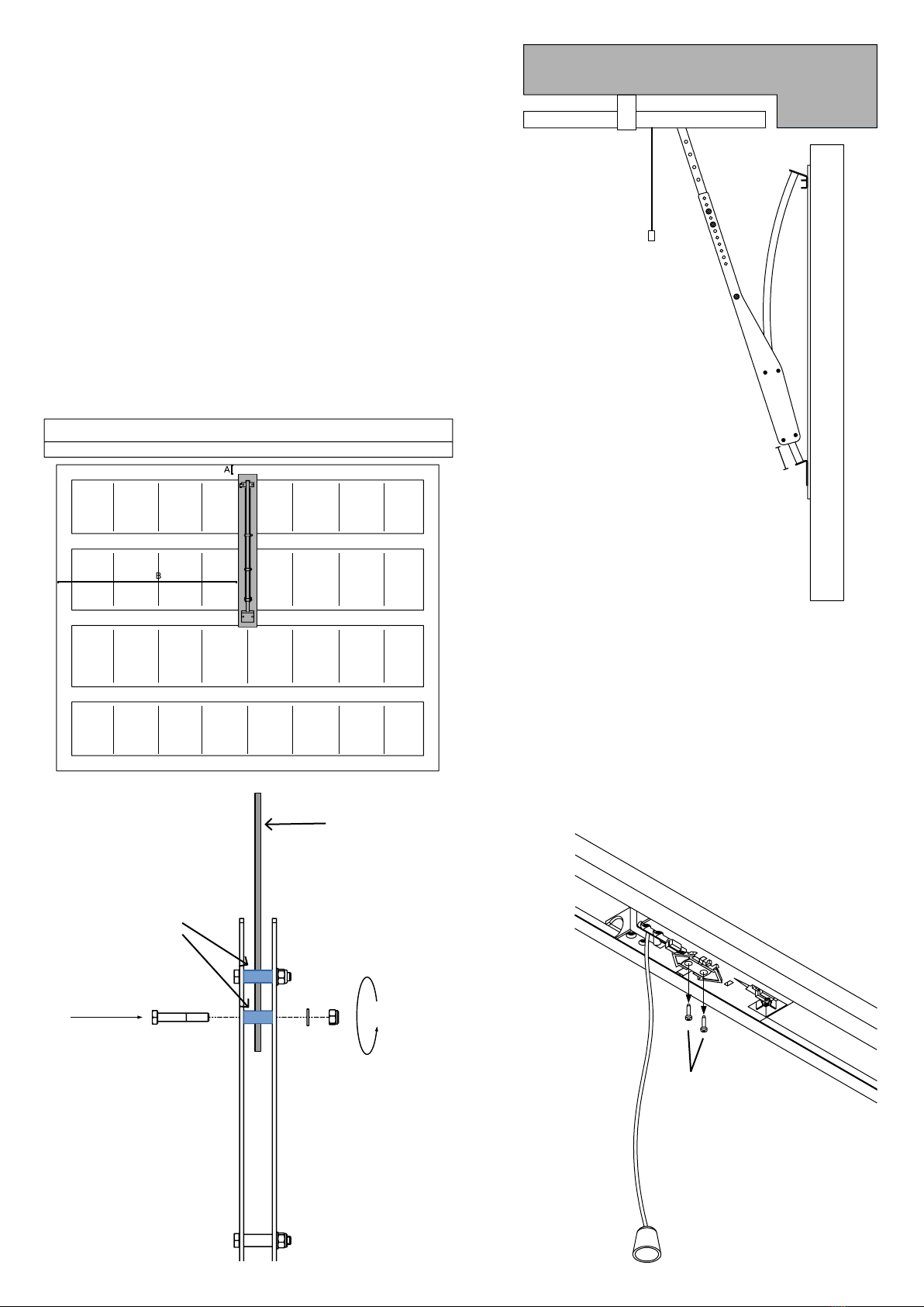
• Fissare l’archetto all’anta con viti, rivetti o tramite saldatura (Non forniti
in dotazione).
• Aggiungereunsupportoinlamierasenonfossepossibilessare
l’archetto a due travetti della porta. (Figura7)
NB: il supporto in lamiera non è fornito in dotazione.
• Collegare il braccio alla guida dell’automazione utilizzando il braccio
di trascinamento montato sul carrello (Rispettare la quota di 60mm
indicata in Figura9).
• Fissare il braccio a longherone con le restanti viti TE 8x50, posizionare
i distanziali 12x11 tra il braccio e le due flange.
InnessareconrondellaedadoautobloccanteM8.(Figura8)
• Controllare che la corsa avvenga in maniera fluida.
• Dopoaververicatolacorsaalimentarel’automazioneeprocedere
con l’apprendimento.
Fig. 8
Fig. 7
Distanziale
12X11
Braccio di
trascinamento
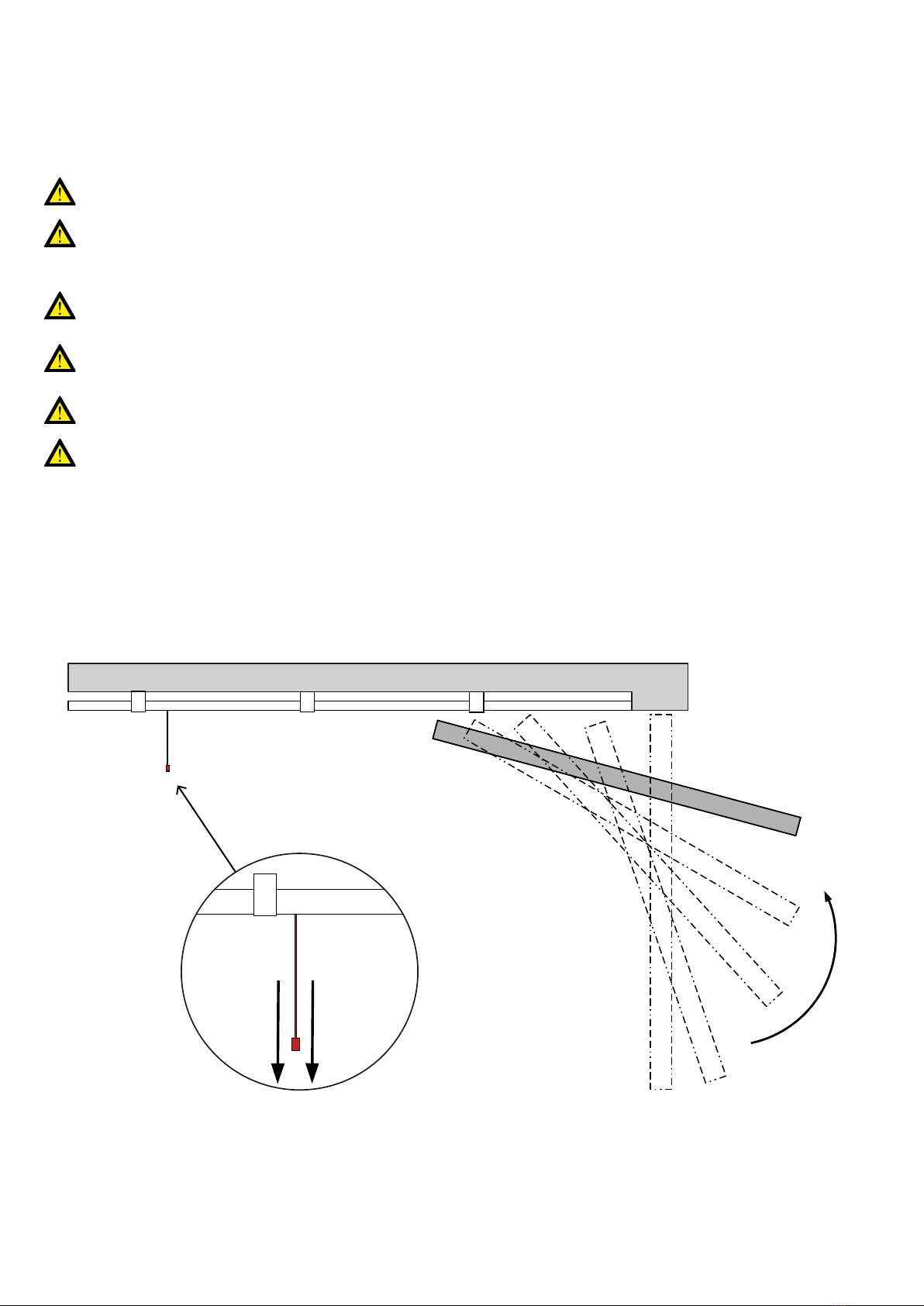
3.3 Rimozione perno d'arresto
Dopo aver montato l’archetto sull’anta del portone, smontare il perno
d'arresto del pattino che impedisce la corretta corsa durante l’azionamento
manuale.
• Svitare le due viti A indicate in Figura10.
• Smontare la copertura dello sblocco facendo attenzione alla possibile
caduta della molla (Figura11).
• Rimuovere la molla dalla sede come rappresentato in Figura12.
• Rimuovere il perno dello sblocco B (Figura13).
• Riposizionare la copertura utilizzando le due viti A (Figura10/11).
Fig. 10
60 mm
Fig. 9
A