8
ENGLISH
ABC
S1
S2
~10cm
~10cm
~10cm
A
B
4. INSTALLING THE AUTOMATION SYSTEM
4.1. PRELIMINARY CHECKS
To ensure safe, proper operation of the automation system, check
the following:
• The door’s structure must be suitable for automation. Make
particularly sure that dimensions of the door meet the
requirements given in the technical specifications and that
the door is sufficiently robust.
• Check the condition of the door bearings and joints.
• Check that the door moves smoothly; If necessary clean the
tracks and lubricate them with a silicone based lubricant.
Do not use grease.
• Check that the door is correctly balanced.
• Remove the mechanical door locks so that when the door is
closed it is locked only by the automation system.
• Check that there is an effective earth connection for the
geared motor.
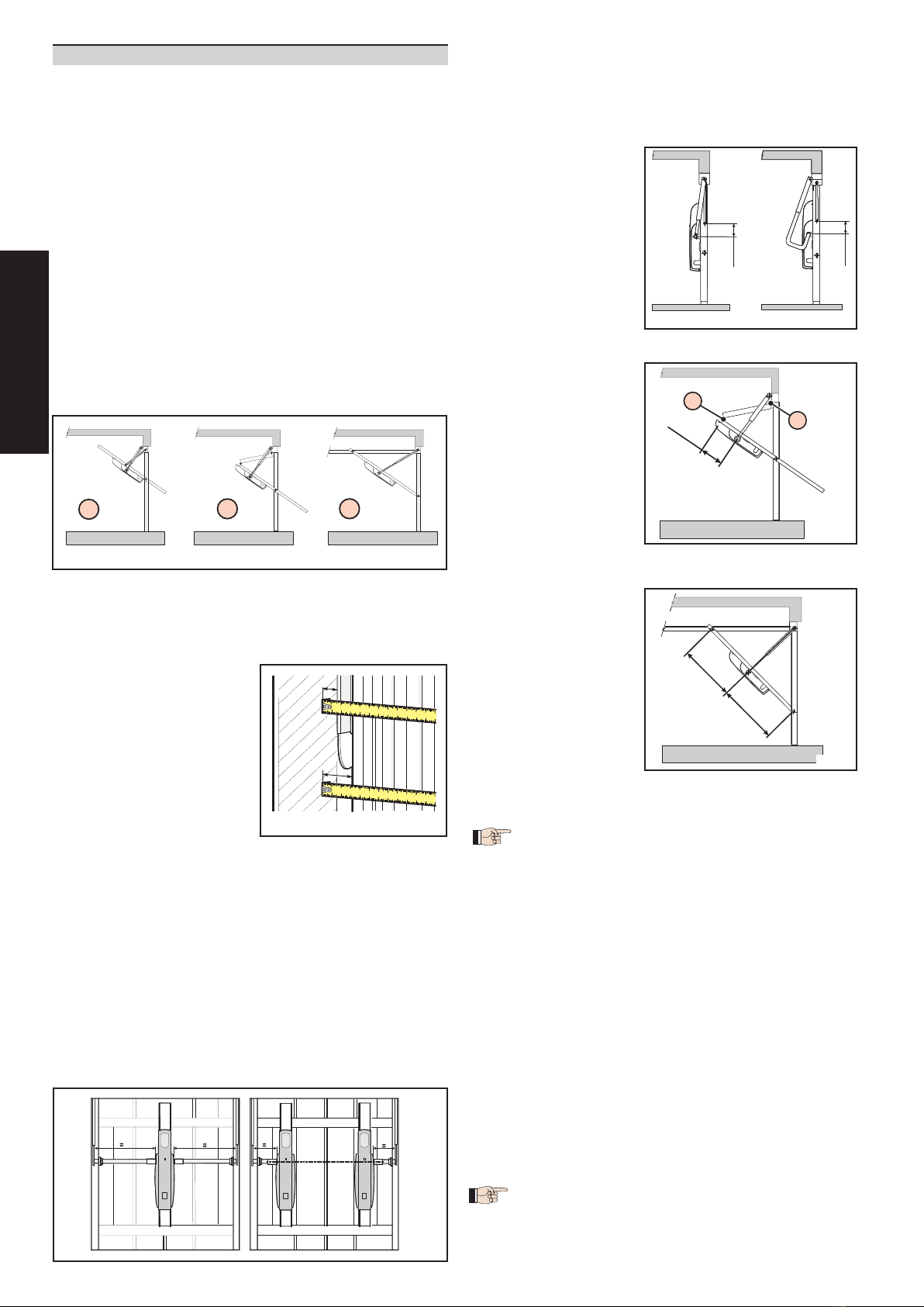
The 550 automation system is designed to operate various types
of counterbalanced up-and-over garage doors. Fig. 4 shows
the most common types:
a) single section outward swinging
b) double section outward swinging
c) single section inward swinging with horizontal tracks
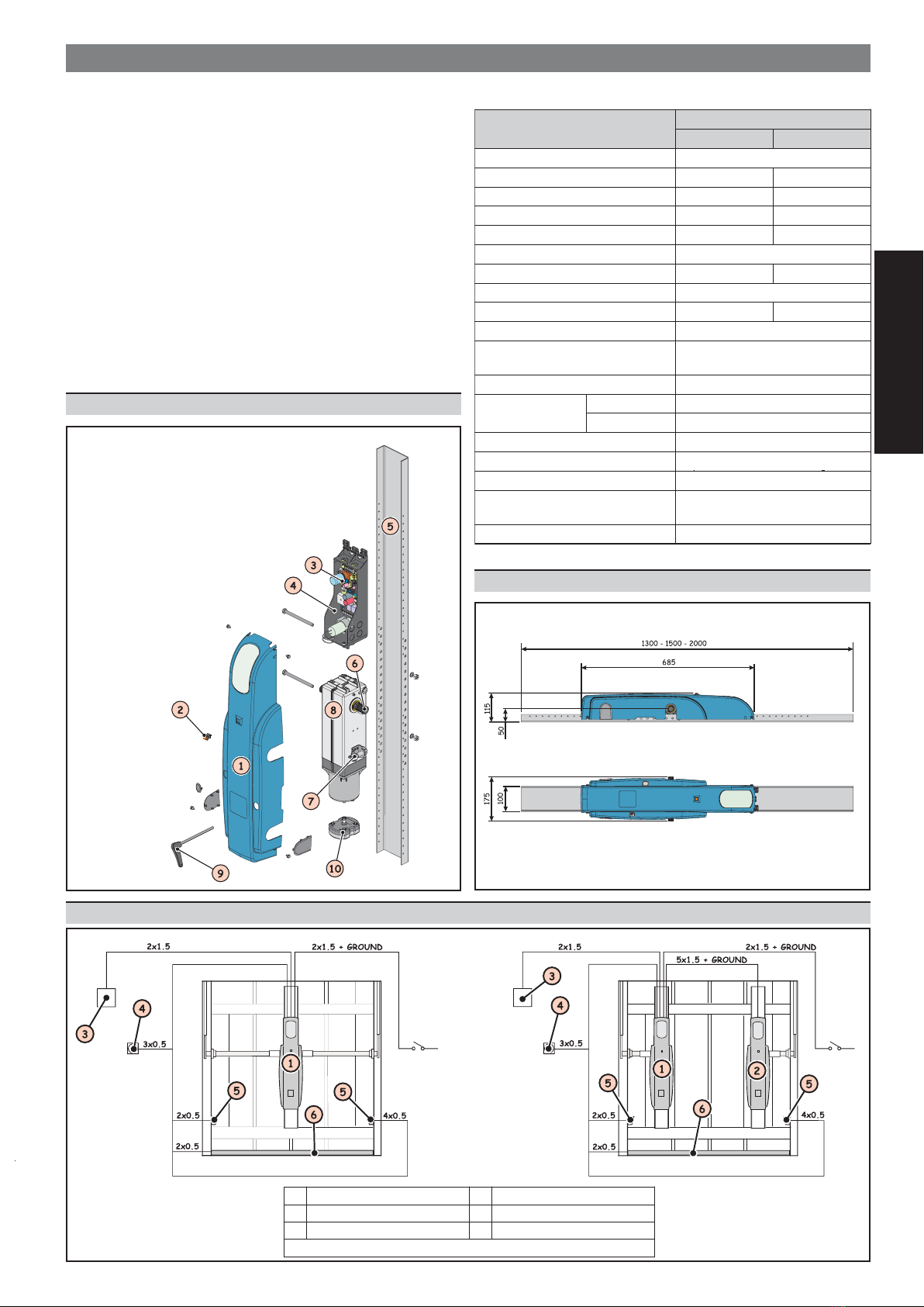
4.3. POSITIONING OPERATOR/BACK PLATE
In accordance with the measurements given in Table 1, install
either a single operator at the centre of the door as shown in fig.
6 or two operators at the sides of the door as shown in fig. 7.
The operator is designed so that the geared motor unit can be
installed with the drive shaft at two different heights (see section
5).
The following instructions apply to both assembly options,
although they refer specifically to installation of the operator
with the geared motor unit output shaft at the centre.
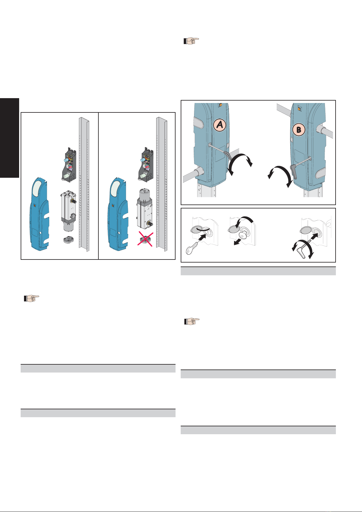
4.4. ASSEMBLY SEQUENCE
Begin installation with the garage door closed and the operator
released (see section 8).
1) Determine the position of the operator shaft as follows:
• single section outward swinging garage door (fig. 8)
When the door is closed,
the axis of rotation of the
drive shaft must be about
10 cm lower than the axis
of rotation of the door.
The telescopic arms must
be attached as close as
possible to the point
where the door arm is
fixed.
•double section garage door (fig. 9)
When the door is closed,
the axis of rotation of the
drive shaft must be about
10 cm below the axis of
rotation of the door hinge.
(A).
The telescopic arms must
be attached as close as
possible to the point
where the hinges are fixed
to the door. (B).
• garage door with horizontal guides (fig. 10)
The axis of rotation of the
drive shaft must be
halfway between the two
bearings.
The telescopic arms must
be attached as close as
possible to the point
where the upper and
vertical guides meet.
2) Fix the back plate to the reinforcement ribbing of the door
panel using suitable screws for the door’s structure. It is
advisable to use nuts and bolts.
• Position the back plate in such a way that the end
with the reference marking E is facing upwards.
This reference marking indicates the point at which
the control unit is to be positioned.
• The back plate has a series of Ø 8mm holes which,
when it is fixed, allow the operator to be installed at
various heights.
• Check that the fixing position of the back plate allows
the operator to be installed in accordance with the
previously determined shaft position.
• In double operator installations, both shafts must be
aligned at the same height.
3) Fix the operator to the back plate using the nuts and bolts
provided, as shown in fig. 11.
4) Weld the upper telescopic arm fixing brackets in the position
described in the instructions for the specific type of garage
door.
In the case of curved arm installation, the brackets can be
welded directly to the existing door arms.
Fix the outer profiles of the telescopic arms to the brackets
using the pins and the nuts and bolts provided, as shown in
fig. 11.
5) Fit the transmission shafts firmly onto the drive shaft and cut
them to size as shown in figs. 6 and 7.
If limit switches are used (optional), first fit the cams as
shown in fig. 11.
4.2. POSITIONING TELESCOPIC ARMS
The gap between the existing
balancing arm and the frame
(distance ”S1” in fig. 5) must be
at least 15 mm to allow the
straight telescopic arms to rota-
te correctly.
If not, it is possible to use curved
telescopic arms which can be
installed over the top of existing
balancing arms. Check that the
gap between the door panel
and the frame is at least 20 mm
(distance ”S2” in fig. 5).
FIG.4
FIG.5
FIG.6 FIG.7
FIG.8
FIG.9
FIG.10