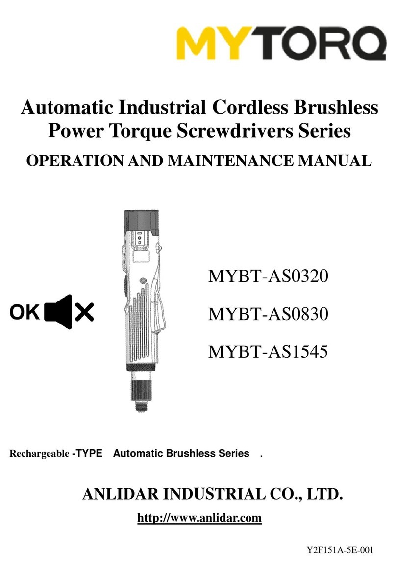
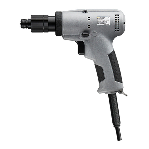
MYTORQ MYBT-AI0822 User manual

Automatic Industrial Cordless Brushless
Power Torque Screwdriver Series
OPERATION AND MAINTENANCE MANUAL
ANLIDAR INDUSTRIAL CO., LTD.
http://www.anlidar.com
Y2F102A-3E-001
MYBT-AI0822
MYBT-AI0615
MYBT-AI0512
MYBT-AI0408
CAUTION!!
MYBT-AI SERIES ISADVANCEMENT IN HIGH TORQUE MOTORS DESIGN.
TO BE MORE SAFTY, ASSEMBLE THE AUXILIARY HANDLE BEFORE OPERATION.

1
Before you use the Cordless Screwdriver for the first time, it is
essential to read and understand the manual completely (including the
spare parts view). The term of “Cordless Screwdriver” in all of the
warning listed below refers to your main operated appliance.
Icon Instructions
1. 2. 3. 4.
5. 6. 7. 8. 9.
1. Read instruction manual.
6. Do not operate in an explosive atmosphere.
2. Observe caution and safety notes.
7. Do not disassemble.
3. Recyclable.
8. Forbid to throw away.
4. For indoor use only.
9. CE certification.
5. Do not expose to wet or rain conditions.
Accessories
Item
Quantity
Unit
Auxiliary handle base
1
PCS
Auxiliary handle
1
PCS
Adjusting Wrench
1
PCS
Manual
1
PCS
Guarantee Card
1
PCS
Torque rings ass’y
1
Package
S Waist hook
1
PCS
Driver hook
1
PCS
Screw M3*0.5P*10LT
1
PCS
Screw M6*50
1
PCS
Socket Extension
(MYBT-AI0822/0615/0512/0408)
1
PCS
BIT
(MYBT-AI0822/0615/0512/0408)
2
PCS

2
Warning
Read all instructions and make sure the appearance of the device has no damage before you use it.
Failure to follow all instructions listed below may result in electric shock fire and/or serious
injury.
1. Keep the working area nice and clean.
1.1 Mess and dark areas may cause of accidents.
1.2 Keep the device away from rain or moisture to decrease the risk of electric shock or short-
circuiting occurred.
2. Be alert to workplace safety
2.1 Use the device under a well lit and clean environment.
2.2 Keep children and other people away unless the person has been assigned for the task to
avoid the danger of injury.
2.3 Do not play around while the tool is being used to avoid the danger of distractions.
2.4 Do not work with the device in potentially explosive environments in which there are
inflammable liquids, gases or dusts. Electrical power tools create sparks, which can ignite
dusts or fumes.
2.5 Do not use the device if you are tired or under the influence of drugs, alcohol or medication.
3. When the devices are not being used, store them in a safe place.
4. Use a suitable device for the job will be safer at work and have a better result.
5. Always use a screwdriver that is intended for the task you are undertaking. Do not overload or
use it improperly such as drilling or tapping.
6. Dress properly. Do not wear loose clothing or jewels while operating the tool to avoid the
danger of trapping.
7. By using the device correctly, make sure to hold it firmly with two hands in place before
starting the trigger.
8. When using the electrical power tool, take into account the auxiliary handle or waist hook is
advantage of working conditions. On the contrary, the purposes of the waist hook or driver
hook is convenient to put the device away and easier to keep it out of reach of children.
9. Look after either the device or the battery carefully and have any damaged parts repaired by
an authorized or qualified shop. Always keep the tool nice and clean; pay attention on the
machine grease which might ruin the tool.
10. Disconnect the plug from the power source after the charger has been used.
11. Take apart the battery from the device when it is not being used.
12. Use only the accessories that are detailed in the operating instructions. The use of others
which are not recommended in the operating instructions may affect the functioning of the
device. It could lead to an increased risk of personal injury as well.
13. Remain alert at all times and watch what you are doing during proceeding. Before operation,
always check every part is in good condition and move freely in order to function properly.
14. This device only applies for metal screw bits designated with their dimensions and their shape.
Do not recommend to countersink or force of loading on any material such as plastic and
wooden.
15. The device does not apply for elastic or tensile load with washer on.
16. To prevent parts in gearbox from damage, replace the grease at least once for every year.
17. It is necessary for the operators to read and follow up all the operating instructions in this
manual. MYTORQ is not responsible for any personal injury that might cause of disobeying
the safety advices.
3
Forward / Reverse
lever
Protection Function
▉Over electric current protection
▉Prevent from low power
▉Thermal Protector
▉Stall protection
▉Slow rotation protection
▉Reverse control protection
▉Battery Identification
▉Sleeping mode
Warning
Do not attempt to repair or disassemble this cordless screwdriver, the warranty
will be considered void.
1. This rechargeable screwdriver maintenance Make sure to remove the battery pack before
maintaining or repairing the device by a qualified technician.
2. Do not attempt to disassemble or reassemble the device at will which may result in poor
performance or danger of injury, the warranty applies only to initial package.
3. Do not repair the device with other than genuine MYTORQ replacement parts may result in
poor performance or danger of injury, the warranty will be considered void.
4. The temperature between 0∘C ~ 35∘C would be an ideal condition of carrying out the tasks on
the device.
Operating instructions
1. Charge the battery in the charge station before first use to make sure operates at its highest capacity.
To ensure operators against injuries, release the Forward/Reverse lever as arrow showing below into
a center position to have trigger locked before start or disassemble the device.

4
2.1 Below illustration is showing the process of correct install & disassemble the rechargeable
battery. The beep sound comes along with a flash while the screwdriver is supplied genuine
battery installation. It could be operated once the battery has been identified.
2.2 Too slow to install the battery may cause error identification so the beep sound and flash would
be continuing. In order to function properly, re-assembling it as below process again.
Insert Battery Steps
(1) Insert the rechargeable battery into the device follow by the arrow as showing.
(2) Assembled completely.
Remove Battery Steps
(1) Press the release button and (2) Follow the arrow direction. (3) Removed completely.
take it out of the device
Battery Release
Button

5
(5)
(4)
(1)
(6)
(2)
(7)
(9)
(10)
(8)
(11)
Function / Operating Introduction
Function Name Table
No.
Description
No.
Description
(1)
Trigger Switch
(7)
S waist hook
(2)
Forward/Reverse Lever
(8)
Indication light
(3)
LED Light
(9)
Torque wrench
(4)
Bit Sleeve
(10)
Speed adjustment
(5)
Torque Ring
(11)
Wrist strap hole
(6)
Driver Hook Hole
(3)

6
Manual / Function
1. Full auto shut-off screwdriver
It stops automatically when the screw has been tightened up and reached the set-up torque level.
The device will not cause damage of task since no continue running after screws are tightened.
(1) Trigger switch
The LED lights on when the trigger switch has been pressed about one-third down, and then the
screwdriver starts functioning when the switch trigger has been pressed half way down; on the
contrary, it stops when the screw has been tightened up or the trigger has been released.
(2) Forward / Reverse switch
When the switch turn to the right as arrow indicates, the screwdriver will be clock-wise
screwing to tighten things up; Vice versa, left switch means to release the screw. As the diagram
showing, always set the switch to neutral position when the screwdriver is not being used.
Forward (screw) Reverse (unscrew)
(3) LED light
While press the trigger, the LED lights up automatically to assist the job to be done; on the
contrary, it will be off once the trigger has been released.
(4) Bit Sleeve
Switch the screw bit and compatibility, pull the head of the type B screwdriver, and install the
bit according to the diagram below, after installing the bit please also install the W type cap and
push it in following the arrow indicated on the diagram below on diagram #2.
Diagram 1 Diagram 2
Pull the bit holder
Insert the bit into
Insert the sleeve

7
(5) Torque ring
The purpose of the color ring is to have the torque level visible; there are 5 different types in
total, follow the diagram below for installation/removal.
1. Remove the color torque
ring from the screwdriver.
2. Tilt the screwdriver slightly upwards
and using the small bit driver to assist
the removal of torque ring.
3. Completed removal.
1. Slightly tilt the screwdriver
upwards about 30 degrees.
2. Install the picked-up torque ring
and push inwards following the
arrow direction.
3. Completed
Installation.
Dismantle
e
Pressed
into
Removal
Install

8
(6) Driver Hook
convenient production lines able to Hook Hanging device balancers work together with the tools
to be more efficiently.
(7) S Waist hook
The S waist hook allows users to carry the device easily by attaching it to their work belt.
(8) Functional light and the status indicator
Whenever the remaining power in the rechargeable battery is fewer than 20%, the tool is still
alive but with red flash lights on. Once the remaining power is towards 10% or even fewer it
may result in poor performance with the continuing red lights on.
Functional indicator
Determine the beep sound
OK screwing with preset
torque
NG screwing
Indicator light
Green on~ off
Red on~ off
Beep sound warning
1 short beep
1 long beep
Indicator of low battery
Power reserve <20%(17.5V)
Power reserve < 10%(17V)
Indicator light
Blinking Red
Red light on ( low power )
Beep sound warning
Continuing Beeping
2 short 1 long beep
Screwdriver functioning
Able to function
Unable to function
(9) Torque adjustable
The torque is able to be changed by following steps
1) Remove the battery from the device or set the rotation switch to
neutral position to prevent the tool from starting up unintentionally.
2) Open up the torque safety cover cap; follow the illustration on the
right which inserting the torque wrench from the bit sleeve to turn
the nut over in a central position, the user may check the nut lock
from side uncovered window.
3) Having the torque changed by inserting the torque wrench into
the nut lock to adjust the torque range.
4) Adjusting the torque in two directions (-) for less torque (+) for
more torque.
Torque adjustment
ring to the + direction
torque increase
Diagram 2
Diagram 1

9
5) The torque wrench as shown in diagram 2: When the torque wrench
rotates clockwise , the torque adjustment ring will be pushed to
the sign (+) direction of the screwdriver, the higher up will be the greater
torque until pushed to the position of highest point will no longer be
able to rise up. Conversely when the torque wrench rotates
counterclockwise , the torque adjustment ring will be pushed to the
sign (-) direction of the screwdriver, the more down will be the smaller
torque until pushed to the position of lowest point will not be able to
downgrade.
Notice: Use the junction of waring plate and spring fixing plate as a reference point when adjusting
torque. To avoid jamming and abnormal conditions, please do not exceed the stop line of the highest
and lowest torque when adjustment shown in diagram 3.
the stop line of the
lowest torque
the stop line of the
highest torque
Diagram 3
(C)
(A)
(B)

10
(10) Hi/Lo Switch
When the rotating speed needs to be changed, set up the switch to Hi for the fastest rotation,
and set up the switch to Lo for slowest rotation. It's possible that the uncompleted shut-off
occurs when the switch is setup to Lo and the presetting torque is more than 50% of torque
range. Please refer to the following table.
(11) Hole for wrist band
Enable to install the wrist band which is more convenient and safer for users.
2. Auxiliary handle
For easier use of the screwdriver, there is a handle for assisting purpose.
Warning, this power screwdriver delivers high torque, please install the
handle before doing work in order to avoid danger. We are not responsible
for any damage or injury caused by using this product without handle.
(1) Installing the base (2) Installing the handle (3) Complete
LoSwitch Shut-off
MYBT-AI0408
MYBT-AI0512
MYBT-AI0615
MYBT-AI0822
OK
4~6N m
5~9N m
6~9.5N m
8~15N m
NG
6N m↑
9N m↑
9.5N m↑
15N m↑

11
Other Cautions
1. The best condition of using the tool is under 8 hours a day, do not over loaded.
2. Do not attempt to repair or disassemble this cordless screwdriver without authorization. Always
have the device serviced by assigned factory or qualified person in order to have the warranty
effective continually.
3. MYTORQ is not responsible for any poor performance or damage caused by customers own
modification of the tool.
4. It is necessary for the management to have individual operators read and follow up all
instructions in this manual. Do not attempt to repair or disassemble this cordless screwdriver
themselves.
5. Chemicals, Acetone, Benzene, Alcohol, Thinner, Ketone, trichloroethylene, etc shall not be in
contact with the surface of the screwdriver in order to prevent chemical damage.
6. Please follow instruction carefully and do not drop or shock the screwdriver.
7. This product allows you to adjust freely ( - ) and ( + ) to decrease and increase torque. Different
models will deliver different level of torque, when the torque is adjusted to the limit the switch
will not be able to turn, please do not force it or it will be damaged. High frequency of using
this power tool might cause overheating, please have the tool to be cool down properly.
8. Not allow to turn the Hi/Lo switch during operation in order to cause system malfunction.
9. The device will not be able to function again once the OK/NG indicator/signal is not turn off
yet.
10. When adjusting the torque, for safety purpose should stop the screwdriver completely and set
the switch to neutral position. It could prevent the user from turning the tool on accidentally.
11. During operation, the switch has been changed accidentally that the device will enable its
self-protecting mode which is power off. Re-start the tool when this happen.
12. Each operational torque setting, using time and frequency may result in different level of wear
and tear, at higher torque setting and use extensively could accelerate the wearing down of tool.
After one month, the torque is getting reduce gradually at the rate of 2~3% or 3~5 %( max
torque). The longer use of the device, torque reduction will become stable and the users could
measure the torque by a tester on a regular time schedule to check if the torque power still
meets the criteria.
13. The torque range of MYBT-AI0822/AI0615 must be measured by the KILEWS torque meter
KTM-250.
The torque range of MYBT-AI0512/AI0408 must be measured by the KILEWS torque meter
KTM-150.
14. MYTORQ cordless screwdriver torque output is generated by clutch mechanism, and it is
applicable to ISO 6789.
Description of Battery and Charger
1. How to choose the correct battery model(SKC-LB series) is depended on the power
consumption of the tool with different torque range. Please contact the local agent for more
detail information. Be sure the small pack model (SKC-LB1820) battery is not allow to apply to
the power torque tools.(MYBT-AI0615/MYBT-AI0822)
2. The use of other than genuine KILEWS batteries or screwdrivers can’t be active due to the
build-in protection system enforce no charging.
3. MYCS-ID120 charger with LED is recommended.

12
Specifications
Bits Code ~ W: square B: Hex 6.35mm
Accessory ~BIT no.:NO.3# Apply to 3.0~4.0mm
CAUTION
SAVE THE INSTRUCTIONS
DO NOT DESTROY
MODEL(MYBT))
MYBT-AI0822
MYBT-AI0615
MYBT-AI0512
MYBT-AI0408
INPUT VOLTAGE(DC)
DC 18V
TORQUE
(N.m)
hard joints
8~22
6~15
5~12
4~8
soft joints
80%↓
8-17.6↓
6-12↓
5-9.6↓
4-6.4↓
Torque accuracy (%)
±3%
Torque adjustment
Internal adjustment
Duty cycle
1.0s ON 3.0s OFF
Unloaded
Speed n0
(r/min)±10%
HI
350
600
720
1200
LO
200
380
450
780
Screw size
(mm)
Machine
screw
≤10
≤8
≤6
5.0~6.0
Weight (Kg)
1.2kg (w/o battery)
1.0kg(w/o battery )
Length (mm)
224 mm *200 mm
(L*H w/o battery )
214mm*197mm (L*H w/o battery )
Applicable auxiliary handle
C15001-2
C15001-3
Applicable battery
SKC-LB1820&SKC-LB1840
Applicable charger station
MYCS-ID120 MYCS-ID80 MYCS-80
Applicable Bit type
This manual suits for next models
3
Table of contents
Other MYTORQ Power Screwdriver manuals

MYTORQ
MYTORQ MYT-0320L-D User manual

MYTORQ
MYTORQ MYBT-AS0320 User manual

MYTORQ
MYTORQ MY9-TR0206L User manual

MYTORQ
MYTORQ MY-SAVER3 User manual

MYTORQ
MYTORQ MYBT-AE0206 User manual

MYTORQ
MYTORQ MYBT-ASP0520 User manual

MYTORQ
MYTORQ MY-SAVER30 User manual

MYTORQ
MYTORQ MYR-0206L User manual

MYTORQ
MYTORQ MYT-TR0206L User manual

MYTORQ
MYTORQ MY-SAVER25 User manual