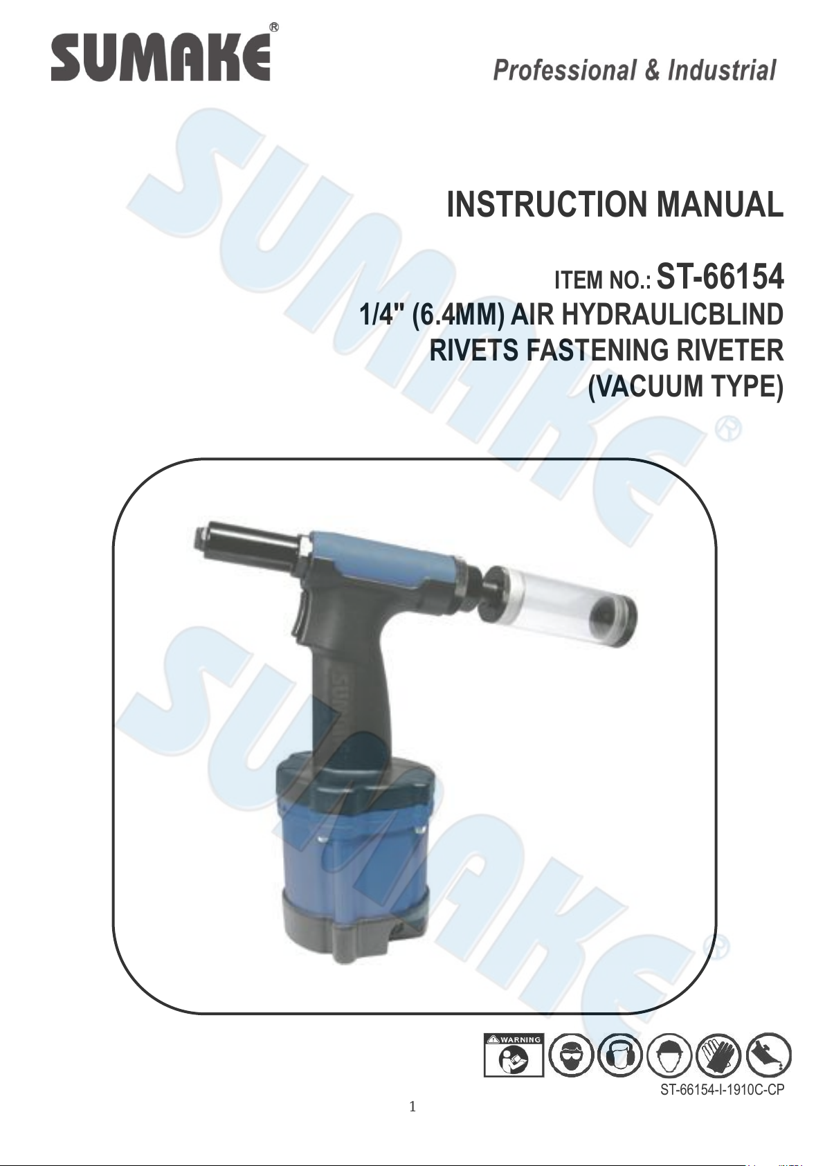
INSTRUCTION MANUAL
OPERATION
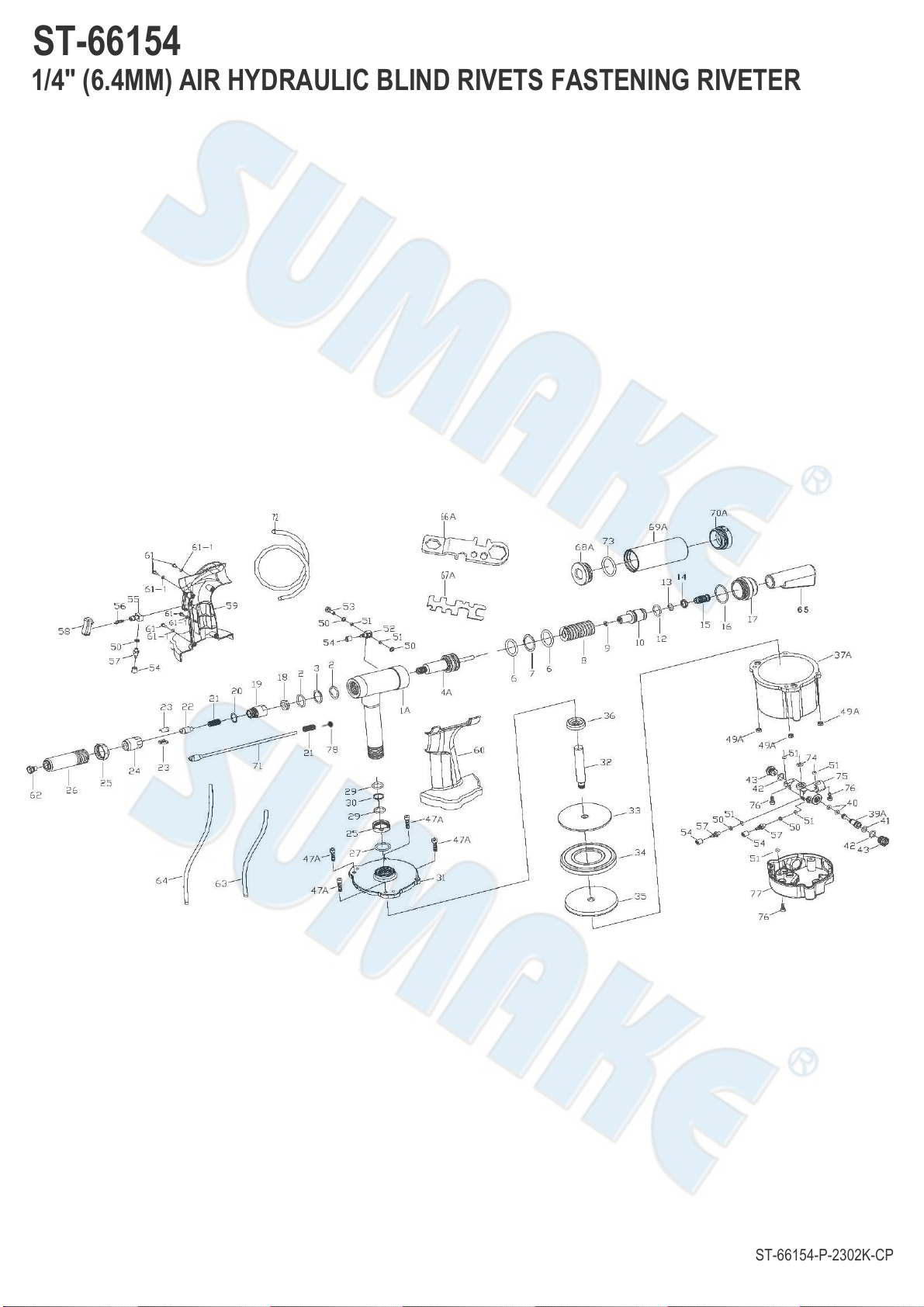
1. When the Trigger (58) is depressed, the Valve Stem (39) is moved off its seat and the air enters the bottom of the Air
Cylinder (39), forcing the Piston Assembly (32~35). As the Piston Assembly rises, the Plunger Rod (32) forces
hydraulic fluid into the upper part of the Hydraulic Section (1), retracting the Hydraulic Plunger (4). Meanwhile, the
Jaws (23) grip the mandrel of the rivet, pulling until the rivet is set and breaking the mandrel in the process.
2. When the Trigger (58) is released, the Valve Stem (39) resets and shuts off the air supply and exhausts the air
through the Exhaust Plug (44). The Return Spring (18) returns the Hydraulic Plunger to its original position. This
open the Jaws, releases the mandrel, and retracts the Piston Assembly back to its original static site.
3. The patented Vacuum Mandrel Collection System is designed and highly recommended for higher productivity, less
fatigue of operators, cleanness and safety of work area. It mainly consists of parts as index #50 to #54 shown as the
exploded drawing. The compressed air is always standing by inside the chamber at the rear portion of the Hydraulic
Section where the Return Spring is contained. The compressed air here will also assure perfect shock absorption
as an air cushion in operation. Through the adjustment of the Vacuum Regulator (15), the compressed air will create
the Venturl effect and vacuum power to hold the rivet in the Nosepiece (62) regardless of the position and suck the
broken mandrel backward to the Deflector (65) or Collection Bottle (68~70) via the Guide Hose (22) to the proper
container.
SERVICING PROCEDURES
1.CHANGING NOSEPIECES
Hook up the tool to the air line and depress the Trigger (58). While continuing to press the Trigger (58) down, use the
Multi-Wrench (66 or 67) to remove the unwanted Nosepiece and tighten the new Nosepiece in place again. When
the Lever/Trigger is released and the tool is at rest, a circular opening should be visible when looking through the
Hydraulic Section from the Rear Gland (17) to the Nosepiece.
2.CLEANING AND CHANGING OF THE JAWS
Disconnect the tool from the air line and then remove the Head (26) with the Multi-Wrench. Hold the Jaw Housing
Coupler (19) firmly and remove the Jaw Housing (24). Clean the Jaws with either a steel brush or solvent. If
excessive wear is apparent, replace them with new Jaws. Before reassembling, apply a thin coat of oil to the sliding
surface of the Jaws. Reassemble the tool in the reverse order while making sure that the chamfered end of the Jaw
Pusher (22) is in contact with the Jaws properly.
3.JAW OPENING ADJUSTMENT
To obtain the maximum stroke of the tool, proper distance-setting between the Jaw Housing and the Head is very
important. First loosen the Lock Nut (25A). A rivet is then inserted into the Nosepiece which should be selected to
match the rivet size to be set. While screwing or unscrewing the Head to achieve the minimum opening of the Jaws,
check if the rivet mandrel can be removed and inserted freely. Fasten the Lock Nut after the adjustment.
4.VACUUM ADJUSTMENT
Loosen the lock Nut (14) and screwing or unscrewing the Vacuum Regulator (15) to obtain the proper vacuum power
for different sizes of rivets for the economy and efficiency of air consumption. Make sure not to damage the nozzle
inside the Vacuum Tube (10). Whether using the tool with vacuum or not, it is necessary to attach the Deflector (65)
on the Vacuum Tube or Rear Gland for the sake of safety.
DAILY CARE
1.Check the tightness of the connections between the Jaw Housing Coupler (19), Nut (18), Jaw Housing (24) and the
Hydraulic Plunger (4), the Nosepiece, the Head (15) and the Lock Nut (25).
2.If the jaws show excessive wear and / or are dirty, follow the steps provided in the SERVICING PROCEDURES section.