Page 4.
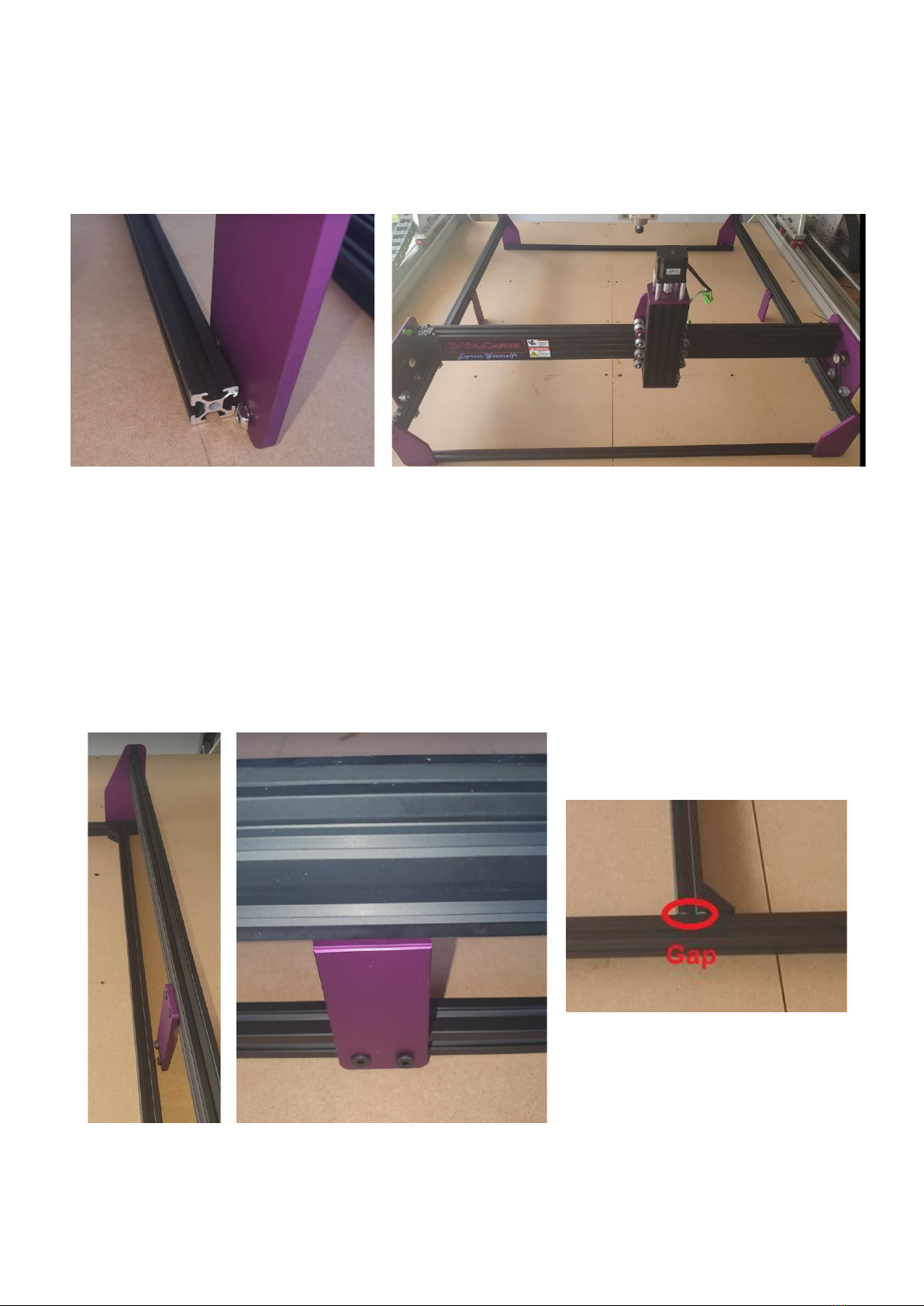
It should now look like this:
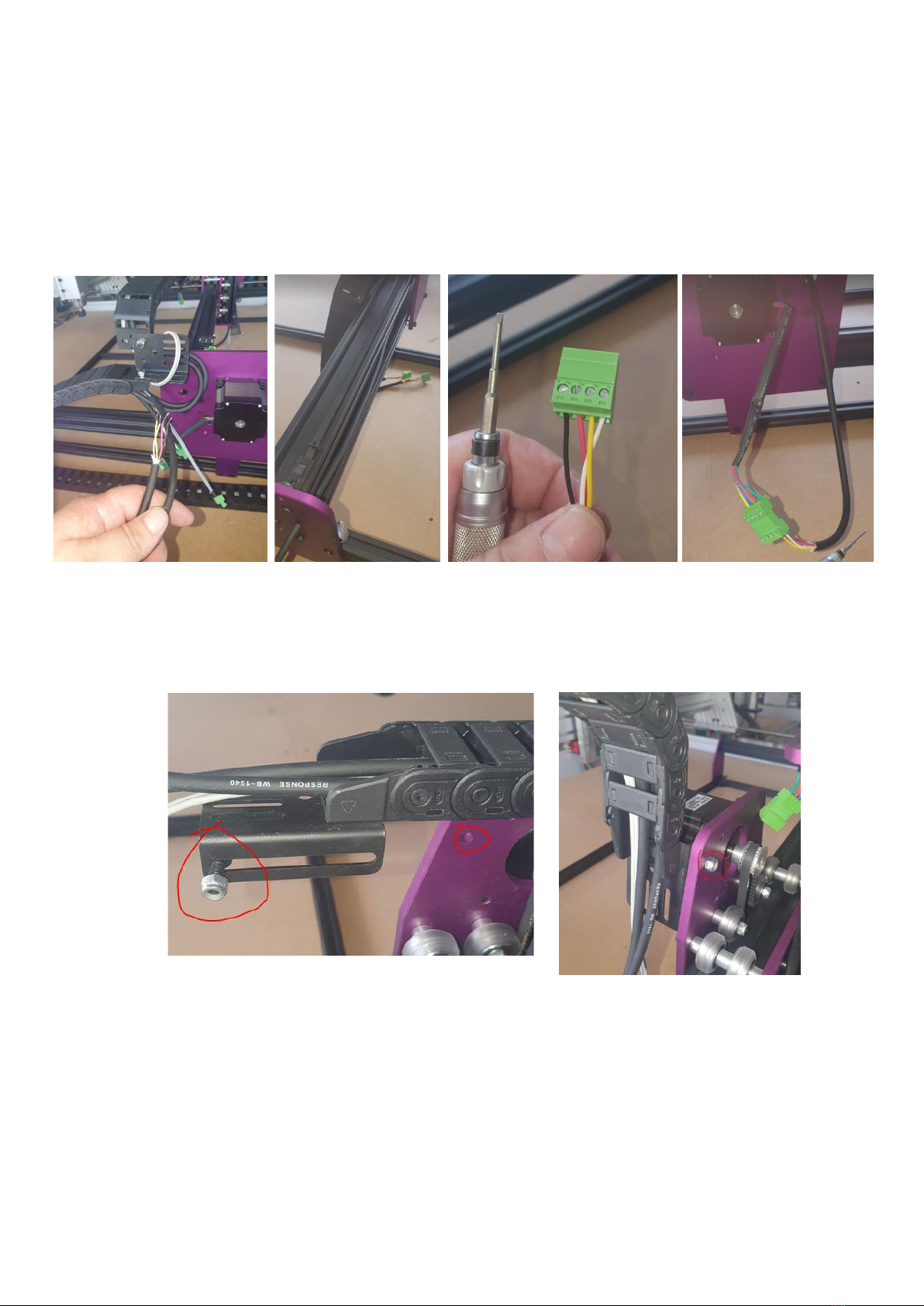
2. Now we are going to fasten the X axis belts and set tension. Firstly, loosen the T-nuts
on the belt tensioners on both sides of the gantry. You will notice on the bolts we
removed earlier that one side is shorter than the other. Starting on the shorter bolt
side, insert the bolt so that it pulls the belt tensioner towards the side plate, once
firmly secured, tighten the downward T-nut bolt into the gantry as per photo. Once
you have secured the short bolt side, proceed to the other side and use the longer
bolt that goes into the side plate to apply tension to your belt. Please Note: You do
not need to put too much force on this bolt and it is OK to have a gap between the
belt tensioner and side plate on this side.