Nacra 500 User manual

: 500, 570, BLAST, I-17, I-18, F-18, I-20
OWNER’S MANUAL
1800 East Borchard Avenue
Santa Ana, CA 92705
tel. (714) 835-6416, fax. (714) 541-6643
website: www.performancecat.com
www.nacraclass.com

always one step ahead
Performance Catamarans has been building recreational high per-
formance multihulls since the early 70’s. We are the original
builders of Nacras, Prindles and Inter Catamarans.
By constantly improving our products each year through trend set-
ting design innovations and the use of the latest construction tech-
niques, we have continued to lead the worldwide multihull market
in design, durability and overall performance – producing
regatta winning results.
By being awarded Sailing World Magazines’ top accolade for per-
formance boat of the year, we have proven to be the innovators in
the industry.

TABLE OF CONTENTS
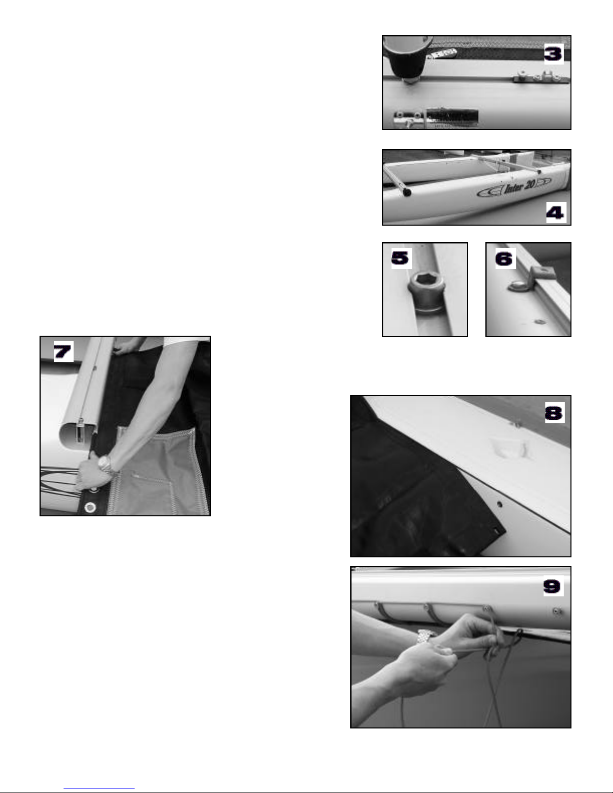
Hull Assembly . . . . . . . . . . . . . . . . . . . . . . . . . . . . . . . . . . . . . . . . . . . . . . . . . . . . . . . . . . . . .4-5
Trampoline . . . . . . . . . . . . . . . . . . . . . . . . . . . . . . . . . . . . . . . . . . . . . . . . . . . . . . . . . . . . . . .5
Spreader Assembly . . . . . . . . . . . . . . . . . . . . . . . . . . . . . . . . . . . . . . . . . . . . . . . . . . . . . . . . .6
Rotator Arm . . . . . . . . . . . . . . . . . . . . . . . . . . . . . . . . . . . . . . . . . . . . . . . . . . . . . . . . . . . . . .7
Downhaul Blocks . . . . . . . . . . . . . . . . . . . . . . . . . . . . . . . . . . . . . . . . . . . . . . . . . . . . . . . . . .7
Halyards . . . . . . . . . . . . . . . . . . . . . . . . . . . . . . . . . . . . . . . . . . . . . . . . . . . . . . . . . . . . . . . . .7
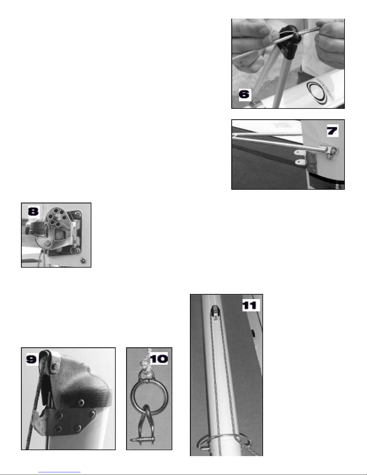
Standing Rigging . . . . . . . . . . . . . . . . . . . . . . . . . . . . . . . . . . . . . . . . . . . . . . . . . . . . . . . . . .8
Roller Furler Jib System . . . . . . . . . . . . . . . . . . . . . . . . . . . . . . . . . . . . . . . . . . . . . . . . . . . . .8
Downhaul Retractor Kit . . . . . . . . . . . . . . . . . . . . . . . . . . . . . . . . . . . . . . . . . . . . . . . . . . . . . .8
Rotator Cleats . . . . . . . . . . . . . . . . . . . . . . . . . . . . . . . . . . . . . . . . . . . . . . . . . . . . . . . . . . . .8
Shroud Adjusters . . . . . . . . . . . . . . . . . . . . . . . . . . . . . . . . . . . . . . . . . . . . . . . . . . . . . . . . . .9
Bridle Wire / Forestay Assembly . . . . . . . . . . . . . . . . . . . . . . . . . . . . . . . . . . . . . . . . . . . . . . .9
Trapeze . . . . . . . . . . . . . . . . . . . . . . . . . . . . . . . . . . . . . . . . . . . . . . . . . . . . . . . . . . . . . . . . .9
Stepping the Mast . . . . . . . . . . . . . . . . . . . . . . . . . . . . . . . . . . . . . . . . . . . . . . . . . . . . . . . . . .9-10
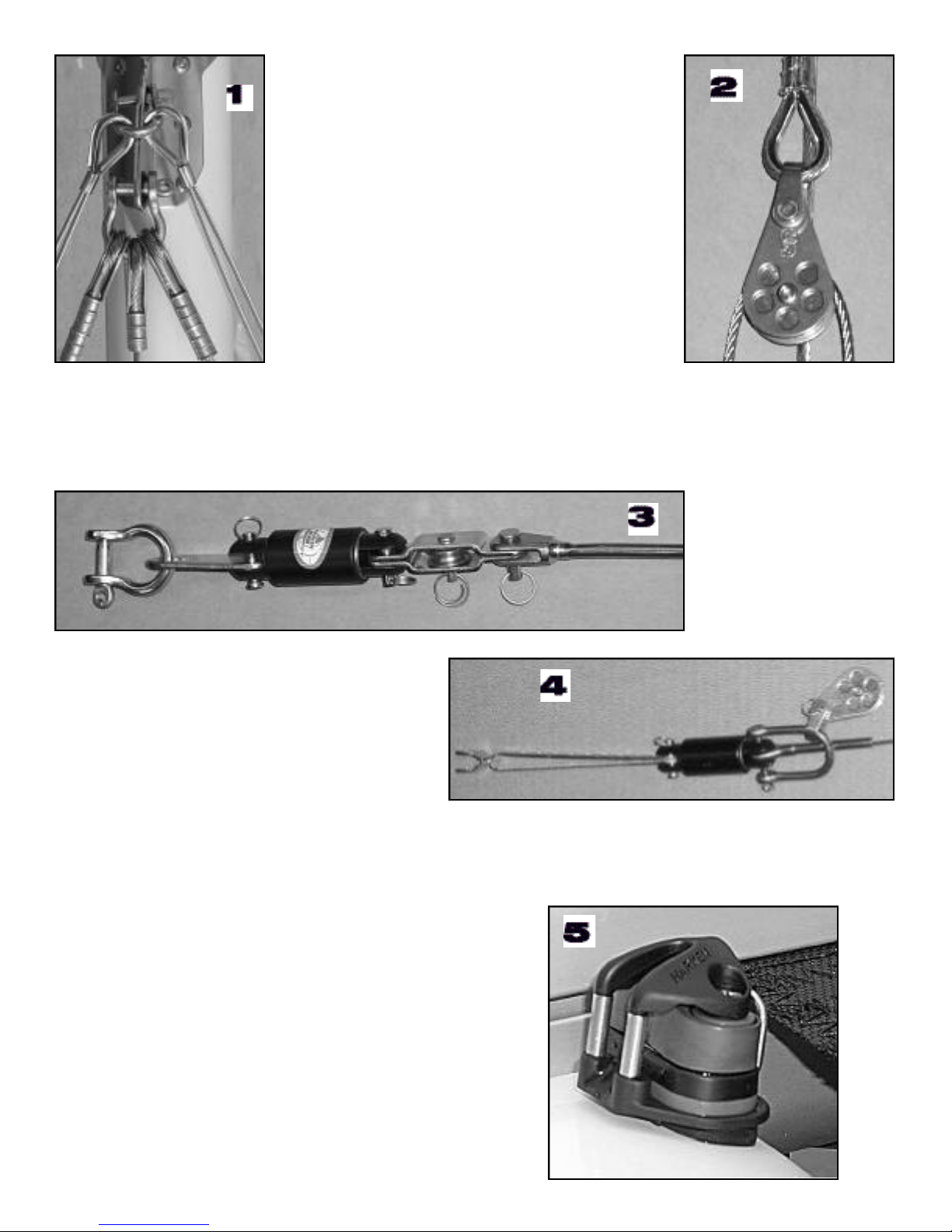
Steering . . . . . . . . . . . . . . . . . . . . . . . . . . . . . . . . . . . . . . . . . . . . . . . . . . . . . . . . . . . . . . . . .11
Jib Sheet System . . . . . . . . . . . . . . . . . . . . . . . . . . . . . . . . . . . . . . . . . . . . . . . . . . . . . . . . . .12
Boom System . . . . . . . . . . . . . . . . . . . . . . . . . . . . . . . . . . . . . . . . . . . . . . . . . . . . . . . . . . . . .12
Rotator System . . . . . . . . . . . . . . . . . . . . . . . . . . . . . . . . . . . . . . . . . . . . . . . . . . . . . . . . . . . .12
Mainsheet System . . . . . . . . . . . . . . . . . . . . . . . . . . . . . . . . . . . . . . . . . . . . . . . . . . . . . . . . .13
Traveler System . . . . . . . . . . . . . . . . . . . . . . . . . . . . . . . . . . . . . . . . . . . . . . . . . . . . . . . . . . .13
Jibsail . . . . . . . . . . . . . . . . . . . . . . . . . . . . . . . . . . . . . . . . . . . . . . . . . . . . . . . . . . . . . . . . . . .13
Mainsail System . . . . . . . . . . . . . . . . . . . . . . . . . . . . . . . . . . . . . . . . . . . . . . . . . . . . . . . . . . .14
Hoisting the Mainsail . . . . . . . . . . . . . . . . . . . . . . . . . . . . . . . . . . . . . . . . . . . . . . . . . . . . . . . .14
Lowering the Mainsail . . . . . . . . . . . . . . . . . . . . . . . . . . . . . . . . . . . . . . . . . . . . . . . . . . . . . . .14
Spinnaker Setup . . . . . . . . . . . . . . . . . . . . . . . . . . . . . . . . . . . . . . . . . . . . . . . . . . . . . . . . . . .14-15
Standard Spinnaker Pole . . . . . . . . . . . . . . . . . . . . . . . . . . . . . . . . . . . . . . . . . . . . . . . . . . . .15
Snuffer System . . . . . . . . . . . . . . . . . . . . . . . . . . . . . . . . . . . . . . . . . . . . . . . . . . . . . . . . . . . .16
I-17 Snuffer System Detail . . . . . . . . . . . . . . . . . . . . . . . . . . . . . . . . . . . . . . . . . . . . . . . . . . .16
Snuffer Halyard Setup . . . . . . . . . . . . . . . . . . . . . . . . . . . . . . . . . . . . . . . . . . . . . . . . . . . . . . .17
Self Tacking Jib . . . . . . . . . . . . . . . . . . . . . . . . . . . . . . . . . . . . . . . . . . . . . . . . . . . . . . . . . . . .18-19
Sailing and Beaching . . . . . . . . . . . . . . . . . . . . . . . . . . . . . . . . . . . . . . . . . . . . . . . . . . . . . . .20
Righting After a Capsize . . . . . . . . . . . . . . . . . . . . . . . . . . . . . . . . . . . . . . . . . . . . . . . . . . . . .20
Trailering and Storage . . . . . . . . . . . . . . . . . . . . . . . . . . . . . . . . . . . . . . . . . . . . . . . . . . . . . . .21
Design Category . . . . . . . . . . . . . . . . . . . . . . . . . . . . . . . . . . . . . . . . . . . . . . . . . . . . . . . . . . .21
Maintenance . . . . . . . . . . . . . . . . . . . . . . . . . . . . . . . . . . . . . . . . . . . . . . . . . . . . . . . . . . . . . .22
Warranty . . . . . . . . . . . . . . . . . . . . . . . . . . . . . . . . . . . . . . . . . . . . . . . . . . . . . . . . . . . . . . . . .23
500, 570, BLAST, 17, I-18, F-18, 20
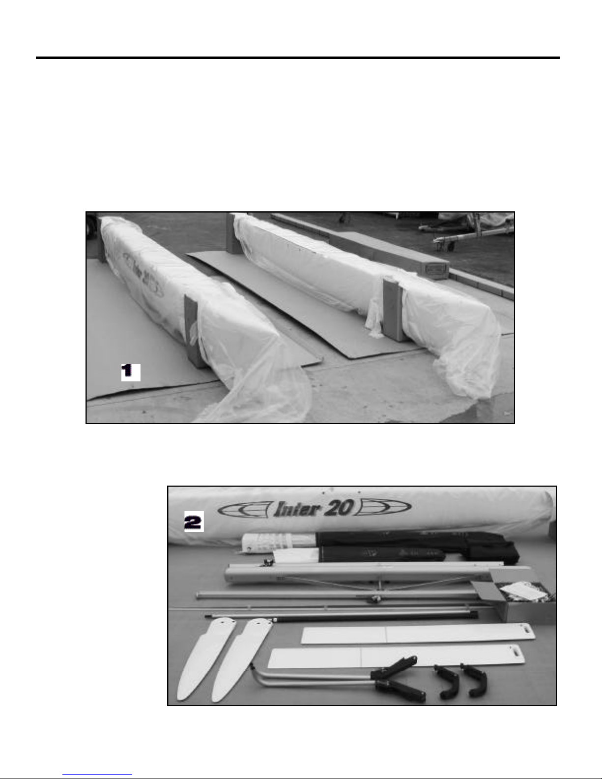
The basic assembly for these models is covered in this manual.
Familiarize yourself with this complete manual to help insure proper assembly and maintenance.
There are variations between models, be sure to follow procedures where applicable.
Variations may also occur based on model, year built, and options.

PLATFORM ASSEMBLY
TOOLS YOU’LL NEED:
9/16” socket Wrench
Phillips Srewdriver
Allen Wrench (included)
HULL ASSEMBLY
Place hulls boxes approx.8 feet apart. Make sure both hulls are facing the same direction, and port
and starboard hulls are oriented correctly. (Pic. 1) Open the boxes, leaving the hulls in the box cra-
dles. Be cautious of the staples- they are very sharp and may scratch the hulls, or cause cuts.
Open the hardware box or boxes and familiarize yourself with all of the parts of your boat.(2) The
hardware boxes may include some or all of the following depending on which model boat you have:
The exact contents for your model will be listed on the sheet enclosed.
• Main beam
• Rear beam
• Rudder box
• Tiller tie bar
• Tiller extension
• Rigging box
• Boom
• Daggerboards
• Sails w/ battens
•Trampoline w/ rod
• Roller furling gear
• Spinnaker gear

If your boat has a jib, but not a self tacking system, open the
bag containing the jib cars. With a phillips screw driver , re-
move the forward beam end caps, and set them aside for re-
installation later, and insert the jib traveler cars onto the beam.
The pin should be on the inboard side of the beam to-
wards the mast as shown in picture 3.
Place the crossbars in the beam sockets on the hulls. Take
time to align them with the pre-drilled bolt holes. (4) From the
rig box, open the bag containing the forward and rear beam
bolts, washers, and grease. The forward bolts are allen heads
(5) . Slide the washers into the track on the front beam. Stack
the 2 types of washers on top of each other. The nylon should
be on the bottom.Grease the beam bolts, and hand tighten into
place. Follow the same steps for the rear beam (6). BE SURE
TO GREASE THE BOLTS. After hand tightening the bolts,
work your way around the boat, tightening all bolts to between
18-20 ft/lbs on a torque wrench.
TRAMPOLINE
Slide the front edge of the trampoline into the slot in the forward
beam.The pocket and straps should be facing up (7).
Next, slide each side of the trampoline into the hull tracks (8). Pull
slowly and evenly on both sides. NOTE: some models have alu-
minum trampoline tracks on the hulls.
Insert the fiberglass or PVC trampoline tie rod or tube
into the slot in the rear of the trampoline.
Attach the lacing line ( 5/32 X 23’). To do this, tie one
end of the line onto the end of the tie bar, and loop the
line under the beam, up around the button, to the next
button, then back under the beam, and around the tie
bar until the trampoline is laced tightly, and tie the end
off (9). Locate the hiking strap tie lines, and tie the hik-
ing straps in place.
NOTE: Some models have an additional side lacing
system & eyestraps instead of buttons on the rear
beam.

MAST AND RIGGING
TOOLSYOU’LL NEED:
1/2” socket wrench
Needle nose pliers
Regular pliers
Rigging tape
SPREADER ASSEMBLY
If your boat is equipped with spreaders,
start by assembling them. Screw the ad-
justable spreader end pieces into the long,
threaded spreader arms, (use grease) ,
and attach the non adjustable end onto
the forward hole on the spreader base (1).
Pin the short spreader arms into the rear
holes. The split rings should be towards
the bottom of the mast.
Connect the two arms together with the spreader tip plate and 3 clevis
pins on each side as shown.
Adjust the spreader rake by removing the pin on the forward arm, and
screwing the adjuster in or out.To measure spreader rake, place a yard
stick or batten between the spreader tips and measure the distance
from the mast to the batten (2).This is your spreader rake. Adjust the
arms until this measurement is at least 1 1/2”.
Attach the diamond wires to the mast. Locate the large turnbuckle, and attach one end to the fitting
near the base of the mast.Remove the clevis pin from the other end of the turnbuckle and pin the thim-
ble end of the diamond wire to it using the special diamond wire plate clevis pin (3) (Single wire only)
and a cotter ring. Pin the forked end of the diamond wire to the upper tang as shown (5).
Diamond wire tension will vary per model based on crew weight and sailing conditions. Diamond wire
tension should be tight initially.
Some models have 2 separate diamond wires- Pin
the turnbuckles to the tangs on the lower part of the
mast (4) . The upper forked end attaches as above
(5).
Tension on the diamond wires must be the same at
both sides of the mast.
NOTE:Be sure to tape all split rings and jam nuts to
prevent snagging and accidental loosening.

Place the plastic spreader cover over the spreader tip and place
the diamond wire in the slot in the spreader tip with the nylon
roller above the spreader arms.Feed the monel seizing wire from
the back side of the tip with on end on each side of the diamond
wire. Lead the wire out of the tip.
Cross the seizing wire over the diamond wire and feed to the
back of the tip. Pull and twist tight with needle-nosed pliers.
Check the wire to be sure that it is held tightly in the slot, and
cannot come out (6).
NOTE:Be sure to tape all split rings to prevent snagging and
accidental loosening.
ROTATOR ARM
Attach the rotator wishbone to the mast (7). Remove the upper
nut on the rotator bolts and attach the arm to this bolt.The lower
bolt is there only to stop the arm from coming into contact with
the boom when sailing. Be sure to tighten both nuts after
installing the arm.
DOWNHAUL BLOCKS
Attach the downhaul swivel blocks to the base of the
mast as shown (8).
HALYARDS
Run the main halyard line through the masthead
sheave and back down through the luff groove in the
mast (9). Tie the halyard lock ring onto the end of
the halyard that exits the top of the mast using a
small bowline. Attach the large twist shackle to the
ring (10).
Spinnaker Halyard
Run the spinnaker
halyard up the star-
board side of the
mast, through the
spreader arms,
through the bale,
around the cheek
block on the mast,
back down through
the bale, and down
the outside of the
mast (11).

STANDING RIGGING
Locate the shrouds and forestay wire or pigtail,
and attach them to the large lower hole in the
mast hound using the 5/16” bow shackle.
Locate the trapeze wires and, using a 1/4”
shackle, attach them to the upper hole in the
mast hound (1).
Shackle the jib halyard block to the forestay pig-
tail. Attach the jib halyard pigtail line to the thim-
ble end of the jib halyard (2).
Secure the shackle with seizing wire. Pull and
twist tight with needle-nosed pliers. Check the
wire to be sure that it is held tightly and tape it to
prevent damage.
ROLLER FURLING JIB SYSTEM
If your boat has roller furling, the forestay assembly will go together as shown. The tang above the
swivel drum attaches to the shackle on the mast hound, and the forestay attaches to the in-line jib hal-
yard block (3).
INTER 18 ONLY:
Assemble the furler/forestay assembly as
shown. The shroud adjuster hooks to the
shackle on the mast hound, and the forestay
attaches to the drum with the D shackle (4).
DOWNHAUL RETRACTOR KIT
Locate the downhaul kit bag, and follow the enclosed directions to install the system. After installing
this system, you can re-install the front beam end caps. NOTE: Not all models have this setup.
ROTATOR CLEATS
There are 2 pre drilled and tapped holes just aft of the for-
ward beam for these cleats. Be sure and use the angled
shim to attain the proper cleating angle (5). NOTE: not all
models utilize this system.

SHROUD ADJUSTERS
Install the shroud adjusters on the hulls using 1/4” clevis pins and
split rings as shown (6).
BRIDLE WIRE/FORESTAY ASSEMBLY
Install the bridle wires to the hulls. Attach the spin pole holder and
roller furling lower assembly (If necessary). Attach the forestay
adjuster. If the forestay adjuster has a tang attached to it, make sure it
faces aft ( 6-10).
Basic Bridle I-17 Pigtail/Forestays Snuffer/Spin w/ FurlingSnuffer/Spin Pole
TRAPEZE
Run the shock cord through the appropriate spot on the hulls, beams,
or trampoline, and tie a bowline in
each end. Tie a trapeze ring to
each of the 3’ lines supplied.
Thread the line through the thim-
ble at the end of the trapeze wire
(12). Thread one of the plastic
adjusters onto the line, wrapping
the line around it at least twice
(11). The adjuster allows you to
adjust the trapeze height. Tie the
tail of the line to the trapeze shock
cord, being careful to not tangle
the trapeze in the shrouds.
In general the trapeze ring should
barely touch the hull.
STEPPING THE MAST
Before raising the mast the boat should be steady on level ground. If the surface is not level, point the
bows downhill. If the boat is on a trailer be sure it is tied down and the trailer tongue is secure to the
hitch.
CAUTION: Check for overhead wires before raising or lowering the mast. A mast which comes in
contact with electrical power lines can cause serious injury or death.

Lay the mast lengthwise on the boat so that the mast rests on the beams with the base forward, and
the sail slot pointing down. Slide the shroud covers over the shroud wires, and pin the shrouds in the
top hole of the shroud adjusters (1).
Walk the mast back-
wards until the base is
even with the mast ball.
Rotate the mast 90
degrees, and pin the
mast base onto the mast
ball. You must keep the
mast turned 90 degrees
until it is vertical to
avoid damage (2).
Make sure the rigging is clear of the rudders and other
obstructions, and the forestay is not tangled in the shrouds
before you begin to step the mast.
One person stands on the tramp near the rear beam, while a second per-
son raises the mast up to the person on the tramp (3). Raise the mast to
your shoulders and walk forward on the tramp while extending your arms
over your head until the mast is upright, being held by the shrouds (4).
Keep forward pressure on the mast as the second per-
son pins the forestay to the stay adjuster that is
attached to the bridle wires (5).Tighten the rig by put-
ting weight on the trapeze wires and adjusting the pins
in the appropriate shroud chain plate holes. Adjust so
the mast is raked slightly aft, or straight up. Rake
adjustment can be set according to boat handling or
wind conditions.
Remove the mast step pin to allow the mast to rotate
freely while sailing.
CAUTION: Check for overhead wires before raising or lowering the mast. A mast which comes in
contact with electrical power lines can cause serious injury or death.
CAUTION: Check for overhead wires before raising or lowering the mast. A mast which comes in
contact with electrical power lines can cause serious injury or death.

STEERING
TOOLSYOU’LL NEED:
Phillips screwdriver Flat head screwdriver
9/16” wrench 7/16” wrench
Attach the upper and lower castings
to the rudder blades as shown (1).
Adjust the rudder rake by turning the
eye screw in or out to the desired
location, and tightening the nut (2).
RUDDER ALIGNMENT
Lock the rudders in the down position
and measure the distance between
the port and starboard leading and
trailing edges of the blades (6). Move
the rudders in or out to attain the
same measurement on both the lead-
ing and trailing edges of the blades.
When the position is correct, install
the self tapping screws into the ure-
thane rod to lock the position.
(Note: allow 1/2” or more rod showing on
each side for proper steering)
Install the completed rudders onto
the pintles so that the curved tiller
arms face inboard (4).
Install the hiking stick on the tiller tie
bar using the hardware with the hik-
ing stick (3). Remove the philips screws from
each of the tiller arms, and insert
the tiller tie bar. Do not screw it in
place yet (5).

JIB SHEET SYSTEM
Install the jib cleat blocks onto the
cars located on the front beam (2).
Be sure to install the stand up
springs.Tie one end of the jib sheet
to the becket on one of the jib
blocks, and thread one of the 2 bul-
let blocks onto the line (1). Run the
line through the cleat blocks and
behind the mast to the other block,
and through the cleat first, and out
through the block. Thread a bullet
block on, and tie the end of the
sheet to the becket on that block.
Attach the jib sheet blocks to the clew of the jib using the
3/16” shackle.
BOOM SYSTEM
Remove the clevis pin from the gooseneck assembly on the
boom, and connect the boom to the bracket on the mast, and pin
in place on the mast (3).
ROTATOR SYSTEM
Tie the 5/16”rotator limiter lines to the diamond wire turnbuckles and lead them back to the clamcleats
on the boom, and install the stopper balls.
From the rotator kit bag, shackle the double airblock and spring onto the mast wishbone, and the triple
onto the eyestrap on the boom (4). Run the line from the cleat on one hull, under the tramp, through
the cheek block on the beam, up through the tramp grommet to the check block on the boom and
through the rotator purchase, and continue to the respective blocks on the opposite side.

MAINSHEET SYSTEM
To thread the mainsheet line, lay the blocks on their side,
or attach them to the boom as if sailing. Start at the lower
block cleat and ratchet, and work your way through the
blocks until complete. Shackle the lower block to the
traveler car with a 1/4” shackle (1, 2).
TRAVELER SYSTEM
Tie the split tailed end of the traveler line to the
two eye straps on the rear beam.Make sure to tie
them so the line joins in the middle, allowing the
traveler car to be centered. Run the line through
the traveler car and cleat. You can tie a stopper
knot, or tie the tail end to the mainsheet line (3).
JIBSAIL SYSTEM
Attach the jib halyard shackle wire
to the head of the jib, and start the
zipper around the forestay. Run the
tail end of the jib halyard line in the
zipper with the forestay, and pull the
jib up, zipping it closed as you pull
on the halyard (4). When the jib is
all the way up, shackle the tack to
the tab on the forestay chainplate.
Remove halyard line and attach the
short line to the halyard, block or
adjuster. Run line through adjuster,
block or halyard (purchase not
needed on recreational boats) then
cleat it off (5). Tension rig before
downhauling jib, forestay should
never be loose within jib.

MAINSAIL SYSTEM
Unroll the mainsail on a clean, flat surface,
and insert the battens into the appropriate
batten pockets making sure that the batten
tips fit into the batten pockets. Fold the bat-
ten tie line in half and loop it through the
grommet on one side of the batten pocket.
Lead both ends of the tie through the batten
and then through the grommet on the oppo-
site side. Tie an overhand knot while push-
ing the batten into the sail with your thumb
(1).Tension the battens enough to eliminate
all the wrinkles from the sail. Finish tying
with a square knot and tuck the loose ends
into the batten pocket.
HOISTING THE MAINSAIL
Always face the boat into the wind
when raising or lowering your sails.
Shackle the main halyard twist
shackle to the head of the sail and
begin to feed the head into the
sail slot on the mast and pull on
the halyard line (2). Feed the sail
into the track as you pull it up. The
halyard ring will hook onto the hal-
yard hook when the sail is raised
completely (3).
LOWERING THE MAINSAIL
To lower the main, pull on the halyard line to raise the ring above the halyard hook on the mast, and
rotate the mast in either direction. While holding the mast rotated, release the halyard line, and pull
down gently on the mainsail.
SPINNAKER SET UP
Attach the spinnaker sheet
ratchet blocks to the eyestrap
on the hull inboard of the
shroud adjuster (4), or shackle
them to the shroud adjuster (5),
depending on boat model.
Secure the shackle with seizing wire. Pull and twist tight with needle-nosed pliers. Check the wire to
be sure that it is held tightly and tape it to prevent damage.

Mount the spin sheet turning blocks on the front
beam. Depending on your model, these eyestraps
may not be pre mounted- attach them with the sup-
plied rivets approximately 6” inboard of the hull side
as shown (6).
If a spinnaker system is an
option on your boat, install
the spin pole mounting
beam pin in the center of
the beam with 4 rivets as
shown (7).
Install the spin halyard swivel cleat onto the beam
with the rivets provided on the starboard side of
the mast as shown if it is not done so already (8).
If you will be using the snuffer system, install the spin
halyard turning block below the swivel cleat with the
eyestrap and rivets provided.
STANDARD SPINNAKER POLE SYSTEM
Insert the Aluminum spinnaker pole through the bridle fitting
and onto the beam pin. Attach the pole bridle wires to the
appropriate tangs on the hulls (9).
This spinnaker setup utilizes a 2:1 halyard system.
The Halyard comes down the mast, through the turning block
on the spinnaker pole, out to the back to back block, and then
back to the halyard swivel cleat.
The spinnaker is stored on the
spinnaker bag on the trampoline (10).
To hoist the spinnaker, you must unzip
the bag and pull on the halyard. This
will pull both the tack and the head up
to their final positions.
When dousing the spinnaker, release
the halyard from the cleat and pull the
spinnaker onto the boat and pack it
back into the bag.

SNUFFER SYSTEM
Insert the small plastic tube into the hole on the front of
the snuffer Using the 1/4-20 bolt and the two snuffer
eyes, which make up the bridle wire/tack fitting (1).
If you have the carbon snuffer pole, put the
extension and the long tube together to make
one long pole. Insert the snuffer head onto the
long end of the pole.
If you have the aluminum one piece pole, just insert the head onto the pole.
Slide completed snuffer assembly through the pole holder on the bridle/forestay connection, and over
the pin on the beam. Be sure that the protective covering on the pole is in the pole holder ring (2).
Attach the snuffer bridle wires to the forward tangs on the hulls, and tie them to the eye fitting on the
snuffer head as shown. Above (1).
Velcro the snuffer bag onto the pole, and tie the end of the bag to the pin on the pole with the small
line on the end of the snuffer bag (3).
INTER 17 SNUFFER SYSTEM DETAIL
Attach both the snuffer bridle wires to the same tang on the hull as the
forestay bridles, using the small bent tang supplied with the snuffer kit.
Be sure that the plate is on the outside of the hull tang between the
shroud adjuster and the tang (4).
Attach the pole holder to the thin white pole stay wire with the supplied
line, and to the pole bridle wires with clevis pins as shown (5).

SNUFFER HALYARD SETUP
The spinnaker halyard for the snuffer system is a continuous line – the same line acts as the halyard
to raise the spinnaker, and to douse the spinnaker during take downs.
Tie the end of the halyard that comes down the outside of the mast to the head of the spinnaker.
Run the other end of the halyard down the
mast, through the turning block on the main
beam, and through the swivel cleat. Run the tail
of that line (coming from cleat) into the aft end
of the snuffer bag, and out through the snuffer
head as shown (6, 7).
There is a grommet in the middle of the spin-
naker- run the line coming out of the snuffer
head through this grommet and tie it to the strap
towards the head on the opposite side of the sail.
Be sure not to twist the spinnaker when running
the halyard (7,8).
Tie the Tack of the sail onto the snuffer eyes on the
front of the snuffer head (9).
Run the spinnaker sheet through the ratchet block on
the hull, to the turning block on the same side of the
beam, to the other turning block, then to the ratchet
block on the opposite hull.Tie the ends to the clew of
the sail.
Raise the spinnaker by pulling on the halyard line
until the sail is all the way up. To “Snuff” the spin-
naker, release the halyard from the cleat, and pull
on the halyard that comes out of the end of the
snuffer bag.

SELF TACKING JIB
If your boat is equipped with the self tacking jib, the track,
and jib sheet controls will be pre-mounted on the forward
beam as shown (1).
All you will need to do is run the control lines in the cor-
rect manner. You will need to install the spinnaker or
snuffer pole prior to running the control lines.
There are two lines used with the self tacking jib system.
Run the larger line through the swivel block on the beam,
and out to the turning block on the spinnaker pole (3), and
through the single airblock, and continue to the respective
blocks on the opposite side (2).

Attach the single airblock with becket to the traveler car on the jib track as shown. Using the small
twist shackle, attach a single airblock to the clew of the jib (4).
Tie the small line to the airblock floating on the on the large line (6), and run it back to the becket block
on the jib track traveler car, up to the block on the jib, and tie it off on the becket on the traveler car as
shown (4).
GO SAILING! HAVE FUN!
Sample of clew traveler system (5).

SAILING AND BEACHING
ALWAYS WEAR YOUR LIFEJACKET WHILE SAILING YOUR CATAMARAN
• Never sail above your ability.
•Be sure to carry the proper safety gear when
sailing.
•When Launching through the surf, always
head directly into the waves.
•Always know the direction that the wind is
blowing before launching
• Secure the drain plugs before sailing.
•After sailing, remove the drainplugs to equalize
the pressure in the hulls.
•Carry your Nacra or use beach wheels with
cradles whenever possible to minimize keel
wear.
RIGHTING AFTER A CAPSIZE
Even the best sailors flip occasionally, so prepare yourself and the boat for the inevitable.Install a right-
ing line onto the dolphin striker rod below the mast.
The boat will lose speed as it raises up on one hull and usually flips over slowly. Hang on to the boat,
being careful not to separate yourself from the boat if possible.
As the boat flips, sit on the flat surface of the hull that is out of the water. Lower yourself down to the
bottom hull using the mast step as a step. It is important to get yourself to the bottom hull as quickly
as possible to prevent the boat from turning upside down (turtle). Do not let go of the boat, as the
current and the wind may make it hard or impossible to get back onto the boat.
Uncleat the main, jib and spinnaker sheets. Reach around the front crossbar, and throw the righting
line over the top hull. Make sure that the bows are facing into the wind. Move your weight towards the
transom of the boat to make the boat turn to attain the proper angle. Be careful not to shift your com-
bined weight too far forward or aft as this may cause the boat to roll over and turn turtle.If the mast is
pointed directly into the wind, the boat may turn over on the other side when you right it.
Standing even with the front crossbar, the skipper and crew should grab the righting line, and hike out
backwards. You can tie knots in the righting line to keep your hands from slipping during this proce-
dure.If you are single handing, you may need to carry a righting bag to attain the necessary weight to
right the boat.
Once the tip of the mast starts to come out of the water, the boat will right quickly. Be sure to hold
onto the righting line until you can grab the boat and pull yourself up onto it. Be careful to avoid being
hit by the dolphin striker rod as the boat comes down on top of you.The boat will now be pointing into
the wind, and moving forward slowly if at all. Stow the righting line, organize the sheets, and you are
sailing again!
This manual suits for next models
6
Table of contents
Other Nacra Boat manuals
Popular Boat manuals by other brands

Acadia
Acadia AYC CHARTERER Operation manual

Blue Wave Boats
Blue Wave Boats I80 Super Tunnel Specification sheet

Johnson Controls
Johnson Controls Old Town SPORTSMAN BigWater ePDL+ 132 manual

KAYAKS2FISH
KAYAKS2FISH NEXTGEN 11.5 owner's manual

Sea Eagle
Sea Eagle RIB11 Instruction & owner's manual

Oru Kayak
Oru Kayak The Coast Assembly guide