manuals.online logo
Brands
  1. Home
  2. •
  3. Brands
  4. •
  5. Nakamichi
  6. •
  7. Cassette Player
  8. •
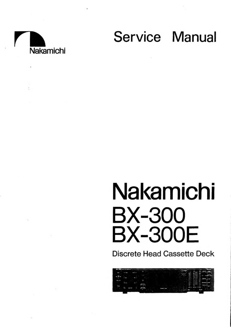
  9. Nakamichi BX-100 User manual

Nakamichi BX-100 User manual

Other manuals for BX-100

1

This manual suits for next models

1

Other Nakamichi Cassette Player manuals

Nakamichi ZX-7 User manual

Nakamichi

Nakamichi ZX-7 User manual

Nakamichi MR-1 User manual

Nakamichi

Nakamichi MR-1 User manual

Nakamichi 700ZXL User manual

Nakamichi

Nakamichi 700ZXL User manual

Nakamichi BX-125 User manual

Nakamichi

Nakamichi BX-125 User manual

Nakamichi 480 User manual

Nakamichi

Nakamichi 480 User manual

Nakamichi CR-7A User manual

Nakamichi

Nakamichi CR-7A User manual

Nakamichi BX-125 User manual

Nakamichi

Nakamichi BX-125 User manual

Nakamichi 1000ZXL User manual

Nakamichi

Nakamichi 1000ZXL User manual

Nakamichi DR-1 User manual

Nakamichi

Nakamichi DR-1 User manual
Nakamichi BX-1 User manual

Nakamichi

Nakamichi BX-1 User manual

Nakamichi 480Z User manual

Nakamichi

Nakamichi 480Z User manual

Nakamichi 1000 User manual

Nakamichi

Nakamichi 1000 User manual

Nakamichi CR-2 User manual

Nakamichi

Nakamichi CR-2 User manual

Nakamichi 500 User manual

Nakamichi

Nakamichi 500 User manual

Nakamichi BX-1 User manual

Nakamichi

Nakamichi BX-1 User manual

Nakamichi BX-2 User manual

Nakamichi

Nakamichi BX-2 User manual
Nakamichi DR-1 User manual

Nakamichi

Nakamichi DR-1 User manual

Nakamichi BX-150E User manual

Nakamichi

Nakamichi BX-150E User manual

Nakamichi BX-100 User manual

Nakamichi

Nakamichi BX-100 User manual

Nakamichi BX-300 User manual

Nakamichi

Nakamichi BX-300 User manual

Nakamichi LX-5 User manual

Nakamichi

Nakamichi LX-5 User manual

Nakamichi BX-2 User manual

Nakamichi

Nakamichi BX-2 User manual

Nakamichi ZX-7 User manual

Nakamichi

Nakamichi ZX-7 User manual

Nakamichi 482 User manual

Nakamichi

Nakamichi 482 User manual

Popular Cassette Player manuals by other brands

Ahuja CPA-360 Operation manual

Ahuja

Ahuja CPA-360 Operation manual

Sony Pressman TCS-60DV Specifications

Sony

Sony Pressman TCS-60DV Specifications

Philips AQ6485/14 Product information

Philips

Philips AQ6485/14 Product information

Sony TCM-200DV - Cassette Recorder operating instructions

Sony

Sony TCM-200DV - Cassette Recorder operating instructions

Panasonic RQ-E25V operating instructions

Panasonic

Panasonic RQ-E25V operating instructions

Aiwa TP-VS535 operating instructions

Aiwa

Aiwa TP-VS535 operating instructions

Yamaha MT8X Operation manual

Yamaha

Yamaha MT8X Operation manual

Sherwood Newcastle D-480 operating instructions

Sherwood

Sherwood Newcastle D-480 operating instructions

Manta MA408 user manual

Manta

Manta MA408 user manual

GPO W0162B user guide

GPO

GPO W0162B user guide

Marantz CP230 Service manual

Marantz

Marantz CP230 Service manual

Sony HST-471 Service manual

Sony

Sony HST-471 Service manual

Sharp JC-AV1 Operation manual

Sharp

Sharp JC-AV1 Operation manual

Pioneer CT-W103 Service manual

Pioneer

Pioneer CT-W103 Service manual

Sony CFS-B15 - Am/fm Stereo Cassette Recorder operating instructions

Sony

Sony CFS-B15 - Am/fm Stereo Cassette Recorder operating instructions

Sony WMFS220 - Portable Sports AM/FM Cassette... operating instructions

Sony

Sony WMFS220 - Portable Sports AM/FM Cassette... operating instructions

Aiwa HS-TA21 operating instructions

Aiwa

Aiwa HS-TA21 operating instructions

Sanyo MCD-ZX700F Service manual

Sanyo

Sanyo MCD-ZX700F Service manual

manuals.online logo
manuals.online logoBrands
  • About & Mission
  • Contact us
  • Privacy Policy
  • Terms and Conditions

Copyright 2025 Manuals.Online. All Rights Reserved.

Nakamichi
Service
Manual
Nakamichi
BX-100
BX-100E
2
Head
Cassette
Deck
CONTENTS
lL
4y
“General
45.5
54
eh
aS
tin
Rae
Oe
ee
Se
Sikca
ls
aCe
een
OR
Bern
a
ete
tena
aa
atone
Bees
snd:
des,
abe
2:
(Mechanical
Adjustments.
i
cic
ssce
cen
ee
ae:
er
ee)
ge
ve)
Sse
he
ene
ld
v6,
(esate
Ey gy
aise
eer
wed
Slavia
egal
ab
wert
a,
ee
egtee
Ze. “Ly
Tape
Guide
Height
Check
for
Record/Playback
Head
and
Erase
Head
.............02
0.000%
2:
2.
Head‘
Base
Stroke
Check:
.0..-24-5-0
ashes
Nw
wee
RE
Se
ee
EA
PR
ee
2.
3.
Record/Playback
Azimuth
Alignment
and
Height
Check
.......
0...
cece
eee
eect
eeene
2. 4.
Pressure
Adjustment
of
Pressure
Roller...
0...
0.
cc
ee ee
ee
te
eee
2.
5.
Tape.
Travellirig:‘CReeh.
5.6
e.0
is
sce
Soe
8
ra
eae
So
eee
Meee
Sas
Sue
aeh
HE
We)
eG
OIG
A
ee
ie
anes
2.
6.
Eject
Damper.Adjustment:
<0.
0c
eesiscee
ie
se
oe
a
eee
oboe
Ue
Bie
HE
ert
Sa
he
hee
ee
ee
2.
7:
Reel
Motor
Speed
Adjustment
in
Play
Mode
........
0...
cc
cece
eee
ee
te
eee
ee
ene
nae
2. 8.
Tape’
Speed
Adjustment:
éiiiic
5
alla
ics
BSG)
alg
ee
We
we
EE
Rie
Bede
Wee
B
Soe
eS
ee
ea
ee
ees
2...
9;
Gur
bricationy
5:55.60
eee
5
ace
Se
ate
wba
We
RPG
Us
womens
Se
ay,
Bee
as
he
OU
ee
we
aw
a
eo
3.
Parts
Location
for
Electrical
Adjustment...
0...
2...
0.
cc
ee
ee
eee
ee
te
ee
ee
ee
ee
tees
4,
Electrical
Adjustments
and
Measurements
...........
52.
-
cece
eee
eee
ee ee
eee
ee
eee
ee
een
eens
4.
1.
Adjustment
and
Measurement
Instructions
......
20...
0.
cece
eee
ee
eee
eee
ee
ee
eee
4,
2.
Playback
Frequency
Response
Adjustment
........
0.0:
ce
eee
ee
eee
ee
eee
eet
ene
4.
3.
Dolby
NR
Circuit
Check
0.0...
cc
ct ce re
ee
nw
ee
eee
ence
ene
n
eens
5...
Mechanism:Ass’y
and
Parts
List.
6.00
(5.6.
oe)
6
Sheie
6
5050s
ay
ES
0G
o
le
aca
fo
al6
Gay
Gre!
WIR
ole
BES
ww
Ra
De
Sere
awa
5.
1.
Synthesis:
ccct
sg
5:3
Sbiel
eee
ee
Beh
a
ee
Se
Nees
tee
Ree
eee
We
Ga
ce
tea
bn
Stee
A
Oya
Wel
a
ee
eae
5.
2.
Synthesis
Mechanism
Ass’y
(A001)
1.0...
ee
ee
ee
eee
eee
eee
eee
5.
3.
Mechanism:
Ass’y:
(BOD)
os
occa
hire
tbe
has:
8
gee
es
Se
Rogues
BERS
OLA
aN
BERL
UD
Gack
Cater
a
onion
bose
5.
4.
Rear
Panel.
Ass’y.(BO2):
055.
coce
cc
ardy
gece
deece
la
Goes
wae,
oh
lah
as
©
pe
Gite
SENS
Wt
we
dte lhe
-8
eg
Rss
agenda
6.
Mounting
Diagrams
and
Parts
List
........
0...
cc
cece
eee
ee
ee
ee
eee
eee
ee
eee
een
eee
ene
ee
6.
1.
Power
Switch
PC:
BiASs’y
<<
faci
8s.
Sak
eI
ar
%
wie
PS
SO
3
a
Sas.
3S
donate
Ws
Saal
ew
6.
2
Shut-off:
PC.
BsAss’y
sie
6.
sieve
cca
ae
ale
at's
belo
ode
de
eee~
alee SNR.
Nw
Ww
wise
Dh
apanss
toss
Wale
base
6.
3
Control:Switch:
PCBs
Assy:
sec
-n
esd
eso
aie
8
6.
0
eee
a
eae
a
cele
ens
Os
fe:
eh
0g
os
eae
ete
wee
ec
eh
else
6.
4
Timer
Switch:
P:C-B:
Asst
y=
cies
s0c
6S
Seay
aheng
oe
ai
S04
Soll:
aod
ese
SE
ey
to
we
giial
MER
en
Sl
nal
wa
SO
BS
OF
6.
5.
Volume:
P.C.B..
Ass?
yi
2.5.38.6
Bee
Seen
Eo
Acdo
wR
case
ae
ede
Seen
e
evened
Roe ees ane
SOM,
Bee
alee
ed
6.
6.
Dolby
NR:P.C:.B:
Ass’¥)
eis
goer
eek
eas
dhe
aces
te
eee
Bae
le
le
eae aes
Rake
eee
ete
GIG
eel
6.
7
Tape
Switch:PiC
Bs
Asse’
y
4.coccce-goa
io,
ci/a2%
ge
18>
wi
Bhs
6D
lallav
eying)
tale
So
co
8i
Ste
rece
oa
aby
SGT
aa
Recetas
e
6.
8.
Indicator-P:C.B.
ASS’Y
cc
bees
ae
ew
EN
hw
Se
ee
He
es
Eta
i
Se
ee ae oP
alee
SMe
ee
6.
9.
Main:
PC.
BisAss’y
orteco
ed.
ca
ace
ods
ake,
Sub
tierenat
gscgeesr
ee
eS
ree
&
pw
eed:
Shore
el
Sia
ales
WS
aria
te
wa
oar
T
Sehematic
Dis
graimia..25.6..25-6
coed
Sins
Soe
Ne
Bo
GSO
BEE
wlan
a
ecg
gs
we
See
Ee
a
baa
ee
arcbuceris
dao
Gla
a
EEF
ee
Attention
to
Servicemen
2.666.606.5460
ee
ee
bale
Be
ele
be
Oe
ae
eco
elas
2
ETE
be
ees
7.
2.
IG/Bloek:
Diagrarniss
2
sic
ies
din
eee
ee
oso
Wee
aaa:
wo
eee:
Bree
a
et
ee
Mebane.
hata
aye
Bw
Ree
eel
7.
3.
Schematic-Diagrarns:.%.<.
o).ee-
cits
science
Ghee
gees
a8
5
OR
GST
WS
Rew
ieg
ecw
ERS.
WGN
Et
Teac
Sag
Wa
ES
ie
Bio
“Wiring
Diagrarny
oss
oisb
5
sor5
Sor
Sees
esi
oa
a
0a
AES
Wve
daye
MES
Bee
SN
Mea
Se
cea
oa
ca,
Seige
rena
ees
ay
oh
alanie
eee
eccaytee
es
9:
‘Block:
Diagrams
0:52.
86353
Gk
aia
wales
idl
cob
a4
eee
pe
Neate,
oo
aren
aa
Tee.
eee
wah
aries
Va
eye
aed
cateneral
ae:
SiN
a
aT
10.
Timing
Chart
and
Eq.
Amp.
Frequency
Response
.......
0.0...
cee
eee
eee
ee
eee
te
eee
eee
11,
Specifications
.............06--
Sig
et
GN
a
tas
Sie
Aa
dk
Rey Sao
WAG
Ma,
See
LaES
Se
ee
eRe
Taro
eee
lo
MACE:
Genres
tak
td
Sass
1.
GENERAL
1.1,
Voltage
Selector
Voltage
selector
is
installed
on
the
rear
panel
for
Other
version
of
the
Nakamichi
BX-100.
This
voltage
selector
can
select
either
120
V
or
220-240
V
at
customer’s
disposal.
1.2,
Packing
Materials
and
Owner’s
Manual
Part
No,
Description
Q
OFO3736A
Carton
Box
BX-100
(Silver)
OFO3750A
Carton
Box
BX-100E
(Silver)
OF03737A
Carton
Box
BX-100
(Black)
OF0O3751A
Carton
Box
BX-100E
(Black)
OF03674B
Packing
0D04311A
Owner’s
Manual
(BX-100.(U.S.A.,
Canada
&
Australia)
&
BX-100E
(UK))
0D04317A
Owner’s
Manual
(BX-100
(Others)
&
BX-100E
(220V
Class
2))
¢
<
BRN
HH
ee
1.3.
Serial
Number
The
BX-100
has
two
versions,
Silver
and
Black.
In
the
service
manual,
serial
numbers
of
these
versions
are
identified
as
follows:
Silver
version:
A318xxxxx
Black
version:
A319xxxxx
However,
the
actual
serial
number
on
the
serial
number
plate
of
the
BX-100
is
indicated
as
A318.9xxxxx.
The
serial
number
begins
with
A318.901001.
2.
MECHANICAL
ADJUSTMENTS
2.1.
Tape
Guide
Height
Check
for
Record/Playback
Head
and
Erase
Head
With
use
of
an
M-300
produced
by
Information
Terminals,
tape
guide
height
check
for
the
Record/Playback
and
Erase
Heads
shall
be
made,
wherein
a
small
block
shall
be
pushed
straight
down
to
the
base
while
in
use
of
the
M-300,
Refer
to
Fig.
2.1.
(1)
Record/Playback
Head
Tape
Guide
Height
(a)
Load
the
base
of
the
M-300
carefully,
then
set
the
cassette
deck
in
Play
mode.
(b)
Place
the
small
block
of
the
M-300
on
the
base.
(c)
Slide
the
small
block
against
the
tape
guide
of
the
Record/
Playback
Head,
and
check
to
insure
that
the
block
is
ac-
cepted
by
the
tape
guide.
(d)
If
not,
loosen
the
screw
and
insert
a
shim
(either
30
um
(0C80048A),
60
um
(0C80038A),
or
100
um
(0C80039A))
to
raise
the
Record/Playback
Head,
then
tighten
and
apply
a
quantity
of
lock
tight
paint
to
the
screw.
(2)
Erase
Head
Tape
Guide
Height
(a)
Load
the
base
of
the
M-300
carefully,
then
set
the
cassette
deck
in
Play
mode.
(b)
Place
the
small
block
of
the
M-300
on
the
base.
(c)
Slide
the
small
block
against
the
tape
guide
of
the
Erase
Head,
and
check
whether
the
block
is
accepted
by
the
tape
guide,
2.2,
Head
Base
Stroke
Check
Refer
to
Fig.
2.2.
(1)
Load
the
base
of
the
M-300
carefully,
then
push
the
base
toward
the
Record/Playback
Head
to
eliminate
the
clearance
between
the
reference
pin
and
the
base.
(2)
Setthe
cassette
deck
in
Play
mode,
(3)
Place
the
small
block
of
the
M-300
on
the
base,
(4)
Contact
the
small
block
with
the
Record/Playback
Head
sur
face
and
the
Erase
Head
surface,
and
check
whether
the
end
of
the
small
block
is
located
within
the
specified
tolerance
as
shown
in
the
figure.
2.3.
Record/Playback
Azimuth-
Alignment
and
Height
Check
Refer
to
Fig.
2.1.
(1)
Connect
a
VTVM
to
the
Output
Jacks.
(2)
Load
a
15
kHz
Azimuth
Tape
(DA09004B),
then
set
the
cassette
deck
in
Play
mode.
(3)
Tum
the
Azimuth
Alignment
Screw
until
the
outputs
of
both
channels
become
maximum.
(4)
Load
a1
kHz
Track
Alignment
Tape
(DA09007B),
then
set
the
cassette
deck
in
Play
mode.
(5)
Check
to
insure
that
the
readings
of
both
channels
on
the
VTVM
are
below
—25
dB.
If
not,
replacement
of
the
Record/Playback
Head
will
be
required,
(6)
Apply
a
quantity
of
lock
tight
paint
to
the
Azimuth
Align-
ment
Screw,
2.4,
Pressure
Adjustment
of
Pressure
Roller
Refer
to
Fig.
2.3.
(1)
In
Play
mode,
measure
the
torque
of
the
Pressure
Roller
and
check
whether
the
torque
is
in
a
range
of
320
+50
g-cm.
(2)
If
torque
is
out
of
the
range,
correct
it
by
changing
the
instal-
lation
point
of
the
Pressure
Roller
Spring.
2.5.
Tape
Travelling
Check
Load
the
Tape
Travelling
Cassette
(DA09027B),
then
set
the
cassette
deck
in
Play
mode
and
check
the
following:
(1)
After
more
than
2
seconds,
the
fluctuation
of
the
tape
trav-
elling
on
the
Record/Playback
Head
is
small.
(2)
Tape
is
in
contact
with
the
head
sufficiently.
(3)
Tape
waving
is
smali
on
the
heads
and
pressure
roller.
2.6.
Eject
Damper
Adjustment
Refer
to
Fig.
2.4.
Load
a
cassette
tape,
and
with
opening
the
Cassette
Case
by
pressing
the
Eject
button
and
closing
it
by
hand,
adjust
the
speed
of
damper
movement
by
the
Adjustment
Screw.
cCW:
Damper
moves
fast.
CW:
Damper
moves
slowly.
Fig.
2.3
Decrease
Increase
Damper
Adjustment
Screw
2.7.
Reel
Motor
Speed
Adjustment
in
Play
Mode
(1)
To
warm-up
the
cassette
deck,
load
a
C-60
cassette
tape
and
set
the
cassette
deck
in
Play
mode,
(2)
After
more
than
four
minutes,
load
a
torque
meter
TW-211
(made
by
Sony)
and
set
the
cassette
deck
in
Play
mode.
(3)
Adjust
VR601
on
the
Main
P.C.B.
Ass’y
to
obtain
exactly
50
g-cm
on
the
torque
meter.
2.8.
Tape
Speed
Adjustment
Refer
to
Fig. 2.5.
(1)
Connect
a
frequency
counter
to
the
Output
Jacks.
(2)
Load
a
3
kHz
Speed
and
Wow/Flutter
Tape
(DA09006C)
and
play
it
back.
(3)
Adjust
the
Tape
Speed
Adjustment
Volume
incorporated
in
the
Capstan
Motor
to
obtain
3,000
Hz
on
the
frequency
counter,
CCW:
Motor
drives
slowly.
Cw:
Motor
drives
fast.
2.9.
Lubrication
The
tape
transport
is
of
a
lubrication-free
type
mechanism.
When
the
following
parts
are
replaced,
apply
the
specified
lubricant.
(1)
Molykote
(R)
Grease
(X5-6020)
Cam
Motor
Pulley
Thrust
portion
on
the
Capstan
Shaft
(2)
FLOIL
GB-TS-1
Washer
between
Reel
Hub
Ass’y
and
Back
Tension
Spring
(3)
Diamond
Oil
(EP56)
Reel
Hub
Shaft
(4)
Anderol
456
Capstan
Shaft
Note:
We
suggest
that
you
use
the
above
specified
lubricant
or
equivalent
type.
The
company
dealing
in
the
above
lubricant
is
as
follows:
(a)
Molykote
(R)
Grease
(X5-6020)
Dowcorning
Co.,
Ltd.,
1-15-1
Nishishinbashi,
Minato-
ku,
Tokyo,
Japan
(b)
FLOIL
GB-TS-1
Kanto
Chemicals
Co.,
Ltd.,
2-7
Kanda
Sakuma-cho,
Chiy
oda-ku,
Tokyo,
Japan
(c)
Diamond
Oil
(EP-56)
Mitsubishi
Of]
Co.,
Ltd.,
1-2-4
Toranomon,
Minato-ku,
Tokyo,
Japan
(d)
Anderol
456
Toyo
Kokusai
Oil
Co.,
Ltd,,
3-3-5
Hatchobori,
Chuo-
ku,
Tokyo,
Japan
Decrease
NH
Increase
Copstan
Motor
Fig.
2.5
3.
PARTS
LOCATION
FOR
ELECTRICAL
ADJUSTMENT
MPX
Filter
L104
L204
TP101
Playbock
Level
©
VREOI
Reel
Motor
Speed
(Play)
vR108
GL
VRIO1
vR201
ia
Level
vR208
@t
Bios
Trap
1P102@
Rec.Cal
(Record)
al
1P202©
Bit)
a
om
rrmro(@)
orezo3
Peaking
1304
@
Bios
Osc.
Frequency
©
|
Bias
Cut
©
VRIOS
VRIO6
yRI07
(2)
ios
To
VR205 VR206 VR207
Tape
Switch
P.C.B.
Fig.
3
4.
ELECTRICAL
ADJUSTMENTS
AND
MEASUREMENTS
Note:
Electrical
adjustment
should
be
performed
after
mechanical
adjustment
is
completed.
4.1.
Adjustment
and
Measurement
Instructions
Tape
Speed
Adjustment
Meter
Level
Calibration
MPX
Filter
Adjustment
Playback
Level
Calibration
Playback
Frequency
Response
Adjustment
Oscillation
Frequency
Adjustment
SIGNAL
OUTPUT
SOURCE
CONNECTION
3
kHz
Speed
and
Wow/Fliutter
Tape
(DA09006C)
400
Hz
to
Input
Jacks
400
Hz
and
19
kHz
+100
Hz
to
Input
Jacks
Azimuth
Tape
(DA09004B)
400
Hz
Level
Tape
(DA09005B)
400
Hz
Level
Tape
(DA09005B)
10
kHz
PB
Frequency
Response
Tape
(DA0900
3B)
15
kHz
PB
Frequency
Response
Tape
(DA09002B)
20
kHz
PB
Frequency
Response
Tape
(DA09001B)
(—20
dB)
to
Frequency
Counter
to
Output
Jacks
VTVM
to
TP101,
TP201
on
Main
P.C.B.
VTVM
to
Output
Jacks
VTVM
to
Output
Jacks
VTVM
to
TP101,
TP201
on
Main
P.C.B.
VTVM
to
Output
Jacks
Frequency
Counter
to
VTVM
across
the
additional
0.1
2
resistor
VTVM
to
TP102,
TP202
on
Main
P.C.B.
VTVM
to
TP103,
TP203
on
Main
P.C.B.
Playback
Eq.
SW
—
70
us
Record,
Pause
Record,
Pause
Playback
Eq.
SW—
70
us
Dolby
NR
SW
—
OFF
Same
as
above
Record,
Pause
Tape
SW
—
ZX
Eq.
SW
—
70
us
Dolby
NR
SW
—
OFF
Same
as
above
ADJUST-
MENT
Tape
Speed
Adjustment
Volume
Main
P.C.B.
VR108,VR208
Main
P.C.B.
L104,L204
Record/Playback
Head
Azimuth
Alignment
Screw
Main
P.C.B.
VR101,VR201
Main
P.C.B.
R110,R210
R195.R295
R318,R350
Main
P.C.B.
L102,L202
Main
P.C.B.
L103,L203
REMARKS
Adjust
the
volume
incorporated
in
the
capstan
motor
to
obtain
3
kHz
+0.5%
on
the
frequency
counter.
1.
Feed
in
400
Hz,
then
adjust
the
Input
Level
control
to
obtain
90
mV
—0.8
dB
on
the
VTVM.
.
Adjust
VR108
(VR208)
so
that
the
0
dB
segment
of
the
level
meter
starts
illuminat-
ing.
.
Adjust
the
Input
Level
control
to
obtain
90
mV
on
the
VTVM,
then
decrease
the
generator
output
level
by
20
dB.
.
Check
to
insure
that
the
segment
for
—-20
dB
illuminates,
.
Feed
in
400
Hz
and
adjust
the
Input
Level
control
to
obtain
0
dB
(500
mV)
on
the
VTVM.
.
Feed
in
19
kHz,
then
adjust
L104
(L204)
to
obtain
minimum
reading
on
the
VTVM
(minimum
reading
will
be
less
than --30
dB).
Adjust
the
Record/Playback
Head
Azimuth
Alignment
Screw
to
obtain
maximum
readings
of
both
channels
on
the
VTVM.
Adjust
VR101
(VR201)
to
obtain
90
mV
on
the
VTVM.
1.
Load
a
400
Hz
level
tape
and
play
it
back.
2.
Load
10
kHz,
15
kHz
and
20
kHz
PB
fre-
quency
response
tapes
and
adjust
the
record/
playback
head
azimuth
to
obtain
maximum
levels
on
the
VT
VM
with
each
tape.
.
Read
the
maximum
levels
with
each
tape
and
check
to
insure
that
the
levels
against
the
400
Hz
level
tape
are
within
the
follow-
ing
ranges.
If
not,
short
R110
(R210)
or
R195
(R295)
to
obtain
satisfactory
results,
10
kHz
(—20
dB)
—2
dB
to
+2
dB
15
kHz
(—20
dB)
2
dB
to
+3
dB
20
kHz
(—20
dB)
—2
dB
to
+4
dB
Refer
to
the
“Playback
Frequency
Response
Adjustment”
in
item
4.2
for
the
detailed
description.
.
Conduct
step
4
‘“‘Record/Playback
Head
Azimuth
Alignment”.
.
Adjust
T301
to
obtain
105
kHz
on
the
fre-
quency
counter,
.
Connect
an
additional
0.1
2
resistor
in
series
to
the
Erase
Head,
then
connect
a
VTVM
across
it.
.
Check
the
erase
current
by
the
VTVM.
Erase
current
will
be
in
a
range
of
145
mA
to
185
mA
(typically
approx.
165
mA).
If
erase
current
is
not
sufficient,
increase
it
by
shorting
R318
or
R350.
.
After
completion
of
the
erase
current
ad-
justment,
re-check
the
bias
oscillation
fre-
quency,
.
Remove
the
additional
0.1
2
resistor.
.
Short
both
Bias
Stop
test
pins
with
a
clip
to
stop
the
bias
oscillation.
.
Adjust
L102
(L202)
to
obtain
peak
read-
ing
at
21
kHz
on
the
VTVM.
.
Remove
the
clip
from
the
test
pins,
Adjust
L103
(L203)
to
obtain
maximum
read-
ing
on
the
VTVM.
SIGNAL
OUTPUT
ADJUST-
Ee
SOURCE
CONNECTION
|
move
|
MENT
REMARKS
Adjustment
should
be
made
in
the
order
of
ZX,
SX
and
EX,
.
Set
the
Dolby
NR
switch
to
OFF,
.
Connect
a
VTVM
to
output
Jacks,
.
Set
the
BX-100
in
Record/Pause
mode.
.
Feed
in
400
Hz,
then
adjust
the
Input
Level
control
to
obtain
500
mV
(0
dB)
on
the
VTVM.
.
Load
a
reference
ZX
tape
(DA09037A),
reference
SX
tape
(DA09025A)
and
refer-
ence
EXII
tape
(DAO9066A).
.
Adjust
Record
Cal.
VR102
(VR202)
for
ZX,
VR103
(VR203)
for
SX
and
VR104
(VR204)
for
EXII
to
center
positions,
.
Connect
the
VTVM
to
TP102
(TP202)
on
the
Main
P.C.B.
Ass’y.
Adjust
Bias
VR105
(VR205)
for
ZX,
VR106
(VR206)
for
SX
Main
P.C.B.
and
VR107
(VR207)
for
EXII
to
obtain
the
(Level)
following
bias
current
in
Record/Pause
ZX:
mode
(the
VTVM
is
connected
across
a
10-
VR102,VR202
ohm
resistor).
SX:
ZX:
approx.
1
mA
VTVM
to
Record
and
Playback
|
Vp103.VR203
SX:
approx,
0.5
mA
TP102,
TP202
EX:
EXII:
approx.
0.3
mA
on
Main
P.C.B.
z
VR104.VR204
.
Connect
the
VTVM
to
the
Output
Jacks,
and
‘
.
Feed
in
400
Hz
(—20
dB)
and
17
kHz
(—20
VTVM
and
(Bias)
aB),
then
record,
rewind
and
play
them
Distortion
Meter
|
Dolby
NR
SW
—OFF/|
7y,
back.
to
Output
Jacks
ON
|
VR105,VR205
Adjust
Bias
VR105
(VR205)
for
ZX,
SX:
VR106
(VR206)
for
SX
and
VR107
VR106,VR206
(VR207)
tor
EXII
to
obtain
the
same
play-
EX:
hae
devel
at
cael
ae
ae
aB)
and
17
kHz
(—
B)
on
the
VT
%
VEIOLYR20e
.
Feed
in
400
Hz
(0
dB),
then
record,
rewind
and
play
it
back.
Adjust
Record
Cal.
VR102
(VR202)
for
ZX,
VR103
(VR203)
for
SX
and
VR104
(VR204)
for
EXII
to
obtain
0
dB
on
the
VTVM.
.
Repeat
above
9
and
10
two
or
three
times
to
obtain
optimum
performance.
.
Set
the
Dolby
NR
switch
to
ON.
.
Feed
in
400
Hz
(—20
dB),
10
kHz
(—20
dB)
and
17
kHz
(—20
dB),
then
record,
rewind
and
play
them
back.
Check
to
insure
that
the
playback
levels
are
within
+2
dB
against
the
levels
in
Dolby
NR
OFF.
Check
to
insure
whether
the
total
harmonic
distortion
is
less
than
1.0%
for
ZX
and
EXII
tapes
and
1.2%
for
SX
tape.
.
If
above
is
not
sufficient,
repeat
9
to
14
till
satisfactory
results
are
obtained.
.
Set
the
BX-100
in
Record/Pause
mode.
.
Feed
in
400
Hz,
then
set
the
Input
Level
control
to
obtain
0
dB
(500
mV)
on
the
VTVM.
.
Decrease
the
generator
output
control
by
20
dB.
i
—
an
400
Hz
(0
dB)
Record
and
Playback
’
Read
awed
sad
uae
ita
Coad
Anes
Overall
and
20
Hz
to
Tape
SW
—
ZX/SX/EX
;
check
to
insure
whether
the
output
levels
Frequency
17
kHz
VTVM
to
Eq.
SW
—
70
us
Main
P.C.B.
are
within
—20
dB
+4
dB.
Response
(20
dB)
to
Output
Jacks
(ZX/SX)
L102,L202
.
If
above
is
not
sufficient,
adjust
L102
Adjustment
|
Tout
Jacks
120
us
(EX)
(L202)
to
obtain
approx.
—20
dB
on
the
Dolby
NR
SW
—
OFF
VTVM,
then
conduct
step
10
“Record
Level
Calibration
and
Recording
Bias
Current
Adjustment”’,
.
If
above
is
not
sufficient,
precise
re-adjust-
ment
of
step
6
‘‘Playback
Frequency
Re-
sponse’,
replacement
of
Record/Playback
Head
or
check
on
item
2.5
“Tape
Travelling
Check”?
will
be
required.
.
ered
the
tape
with bulk
eraser.
"
.
Adjust
the
Input
Level
control
to
obtain
1kHz
Band
Pass
|
Record
and
Day
back
0
dB
on
the
VTVM,
and
record
the
signals
Filter
and
VTVM
Eq.
SW
—
70
us
on
the
reference
ZX
tape
(DAO9037A).
to
Output
Jacks
Doiby
NR
SW
—
OFF
.
Turn
the
cassette
tape
the
other
way
round
and
play
it
back.
.
Measure
the
difference
between
2
and
3.
.
Erase
the
tape
with
bulk
eraser.
Channel
.
Adjust
the
Input
Level
control
to
obtain
Separation
|1kHz
to
O
dB
on
the
VTVM,
and
set
the
Balance
Measure-
Input
Jacks
control
to
the
extreme
left
(right).
ment
:
.
Record,
rewind
and
play
it
back,
then
mea-
sure
the
R
ch
(L
ch)
level.
1
kHz
to
Input Jacks
Same
as
above
Same
as
above
SIGNAL
OUTPUT
ADJUST-
Erase
the
tape
with
bulk
eraser,
2
Adjust
the
Input
Level
control
to
obtain
O
dB
on
the
VTVM,
and
record
the
signals
on
the
reference
ZX
tape
(DA09037A).
3.
Rewind
the
tape,
set
the
Input
Level
control
to
minimum,
and
then
record
again.
4.
Rewind
the
tape,
play
it
back,
and
then
measure
the
difference
between
2
and
3.
Set
the
Dolby
NR
switch
to
ON,
Feed
in
400
Hz,
then
record,
rewind
and
play
it
back.
Adjust
the
Input
Level
control
to
obtain
3%
Record
and
Playback
Tape
SW
—
ZX
Eq.
SW
—
70
us
Dolby
NR
SW
—
OFF
100
Hz
Band
Pass
Filter
and
VTVM
to
Output
Jacks
100
Hz
to
Input
Jacks
IHF-A
Curve,
Record
and
Playback
sop
eo
NP
Filter,
VTVM
total
harmonic
distortion
in
Playback
mode.
tapout
gaa
and
Distortion
aed
lire
Set
the
Input
Level
contro!
to
minimum
Meter
to
:
then
record
again.
Output
Jacks
Dolby
NR
SW
—
ON
.
After
rewound,
play
back
and
check
the
output
level
difference
between
3
and
4.
Note:
The
filter
of
IHF-A
curve
shall
be
used
in
the
measurements,
Adjust
the
Input
Level
control
to
obtain
0
dB
on
the
VTVM.
2.
Record,
rewind
and
play
it
back.
3.
Read
the
distortion
meter
and
check
to
Record
and
Playback
Tape
SW
—
ZX/SX/EX
Eq.
SW
—
70
us
VTVM
and
400
Hz
to
Distortion
Meter
; ;
Fi
h
Input
Jacks
(ZX/SX)
insure
that
the
distortion
is
as
follows:
to
Output
Jacks
120
us
(EX)
EXI].....
1.0%
or
less
Dolby
NR
SW
—
OFF
SX
gow
hee
1.2%
or
less
yn
1.0%
or
less
3
kHz
Speed
and
Wow/
Flutter
Tape
(DA09006C)
Wow/Flutter
Meter
to
Output
Jacks
Playback
Eq,
SW
—
70
us
Play
back
and
read
the
wow/flutter
meter.
4.2.
Playback
Frequency
Response
Adjustment
R
RIO
R195
Figs,
4.1
and
4.2
show
the
playback
amp,
circuit
for
adjustment
R/P
ya
(nzash
and
the
playback
equalization
curve.
Head
This
adjustment
will
be
required
if
playback
level]
is
not
sufficient
during
playing
back
a
20
kHz
PB
frequency
response
tape.
The
peaking portion
of
the
equalization
curve
compensates
the
gap
loss
of
the
playback
head.
Peaking
level
is
varied
by
the
short
120ps
circuit
of
R110
(R210)
or
R195
(R295).
Lol
{L20)
VRION
(VR201)
Output
390P
Hi
C107
(C207)
C108
{C208}
1000P
GAIN
(dB)
100
400
1K
2K
10K
20K
FREQUENCY
(Hz)
Fig.
4.2
4.3.
Dolby
NR
Circuit
Check
Dolby
NR
circuit
incorporates
a
Dolby
NR
IC
(ZA7300PC)
which
has no
adjustment
point.
Perform
the
following
checks
and
make
sure
that
the
IC
operates
accurately
ie.,
frequency
response
through
IC
is
accurate.
(1)
(2)
(3)
Signal
Source:
1.4
kHz
to
Input
Jacks
Output
Connection:
VTVM
to
TP101
(TP201)
and
negative
side
of
C141
(C241)
on
the
Main
P.C.B.
Mode:
Record/Pause
Connect
a
VTVM
to
TP101
(TP201)
on
the
Main
P.C.B.
Ass’'y,
Feed
in
1.4
kHz
and
adjust
the
Input
level
control
so
that
the
VTVM
may
read
90
mV
(0
GB)
at
each
test
point.
Level
meter
will
indicate
0
dB.
Remove
the
VTVM
from
TP101
(TP201)
and
reconnect
it
to
the
negative
side
of
C141
(C241).
Decrease
the
input
level
(0
dB)
by
20
dB
or
30
dB.
Check
to
insure
that
the
level
at
negative
side
of
C141
(C241)
corresponds
to
the
following
with
the
Dolby
NR
switch
ON
and
OFF.
Input
Level
Level
at
negative
side
of
C141
(C241)
at
TP101
(TP201)
|
Dolby
NR
OFF
|
Dolby
NR
B-Type
9mV
OdB
+3.2
dB
+1.5
dB
2.85
mV
0
dB
+8.2
dB
+1.5
dB
MECHANISM
ASS’Y
AND
PARTS
LIST
5.
5.1.
Synthesis
Fig.
5.1