manuals.online logo
Brands
  1. Home
  2. •
  3. Brands
  4. •
  5. Nakanishi
  6. •
  7. Engine
  8. •
  9. Nakanishi Rotus IM-301 User manual

Nakanishi Rotus IM-301 User manual

Thank you for purchasing ROTUS Air Motor " IM - 301 · IM - 300 ". The attachment andAir Line Kit (with lubricator)
are rquired to drive this Air Motor. Read this and all the associated component Operation Manuals carefully before
use. Always keep this Operation Manual in a place where a user can referred to for reference at any time.
①No heat is generated for long continuous use due to air driven operation.
②Air consumption is 75 Nℓ/min and can be used with air compressor of 1HP (7.5kW).
③By mounting a silencer on the back exhaust air / oil hose, the quiet operation of air turbine is remarkably
improved.
④Ring switch can be FWD./REV. turned to rotate the motor.
⑤AIR MOTOR (IM - 301) has a " free joint mechanism " which prevents a hose from being twisted.
⑥Clean air from tool can put away metal chips because Air Motor (IM - 300) has a chip air mechanism.
* IM - 300 is used with Attachment (IH - 300). IM - 300 can not be used with Attachments except IH - 300.
Model IM - 301 IM - 300
Maximum Motor Rotation Speed 30,000min-1 (rpm) (at 0.4MPa (58psi) Air Pressure)
Appropriate Air Pressure 0.3 - 0.45MPa (43.5 - 65.3psi)
Air Consumption 75Nℓ/min (at 0.4MPa (58psi) Air Pressure)
Supply and Exhaust Air / Oil Hose
Dimensions (With Eraser) Supply : I.D. 䃥3.7 mm x O.D. 䃥5.7 mm Length : 2 m
Exhaust : I.D. 䃥5 mm x O.D. 䃥6.5 mm Length : 2 m
Vibration Level Less than 2.5m / s2
Weight (Except hose) 130g
Noise Level at 1m distance Less than 85dB (A)
Standard Accessories
・Supply and Exhaust Air / Oil Hose・・1pc.
(IM - 301 : K - 206, IM - 300 : K - 207)
・Pin Wrench (K - 233)・・1pc.
・Nozzle (Only IM - 300)・・1pc.
・Silencer (K - 209)・・1 pc.
・Operation Manual・・1set.
ROTUS Air Motor
I
M
-301
・I
M
- 300
OM-K0359E 002
4. CONNECTION OF THE AIR MOTOR TO THE ATTACHMENT
Fig. 4 Connection of Air Line Kit " AL- H1207F (Sold Separately) "
Align the thread on the front end of the Air Motor and the rear of the attachment, and turn the attachment clockwise.
If the drive shaft of the Air Motor does not engage properly to the drive dog on the attachment, it may only turn
aprroximately two threads before stopping. DO NOT FORCE THEM TOGETHER. Loosen the attachment from the
Air Motor, rotate the attachment shaft by hand then re-try. The drive shaft and the drive dog must be fully engaged.
When fully engaged, secure the Air Motor and attachment using the provided wrench. (Fig. 3)
Tighten
Transmission Clutch
Fig. 3
5. CONNECTION OF THE AIR LINE KIT
5 - 1 Connection of the Air Motor
Foot Control Hose (Output) ⑤
Foot Control Hose (Input) ④
Foot Control (AFC - 45)
④
⑦⑥
②
①
⑤
Chip Air Hose (For IM - 300)
Connection Hose
(Chip Air Type)
IM - 300
FR
(360° Free Joint Type)
IM - 301
Exhaust Air / Oil Hose
Supply Air / Oil Hose
Silencer
FR
④ ⑤
Chip Air Adjusting Valve
Filter Joint
Secondary Joint
(ȭ6 One - Touch Joint)
Control Valve
Primary Joint
Connector for Air Hose
Filter Regulator
To Air Compressor
③
Lubricator
Adjusting Dome
(1) Connect the Filter Joint of the Air Motor to the Secondary Joint ( ȭ6 One - Touch Joint) on the Air Line Kit.
(Fig. 4 ①)
(2) Place " Exhaust Air Silencer / Oil Hose " into an empty container (Fig. 4 ②).(Exhaust outlet air and oil from
the Siliencer.)
* If using the ROTUSAir Motor " IM - 300 ", insert the ChipAir Hose to the ChipAirAdjusting Valve on the
Control Valve (Fig. 4 ③).
3- 2Outside View
Fig. 1
FR
9.237.711 43
(100.9)
ȭ22.8
ȭ19.5
(ȭ21.5)
RF
ȭ22.8
ȭ9.5
11 37.7 9.2 39.6
(ȭ15.8)
(97.5)
Fig. 2
5- 2Foot Control Hose Connection (Sold Separately)
(1) Insert the Foot Control Hose (Input) ④to the One - Touch Joint ④of the Control Valve (Fig. 4).
(2) Insert the Foot Control Hose (Output) ⑤to the One - Touch Joint ⑤of the Control Valve (Fig. 4).
1. CAUTIONS FOR HANDLING AND OPERATION
■Read these warnings and cautions carefully and only use in the manner intended.
■These warnings and cautions are intended to avoid potential hazards that could result in personal injury to the
operator or damage to the device. These are classi¿ed as follows in accordance with the seriousness of the risk.
Class Degree of Risk
WARNING
A safety hazard could result in bodily injury or damage to the device if
the safety instructions are not properly followed.
CAUTION
A hazard that could result in light or moderate bodily injury or damage
to the device if the safety instructions are not followed.
WARNING
①This product is designed for hand use. Never install this attachment or any hand tool on a
machine such as a special purpose machine, NC lathe or mill.
②Do not touch the cutting tool while it is rotating. It is very dangerous
③Always wear safety glasses, dust mask and use a protective cover.
①Do not drop or hit this Air Motor, as shock can cause damage to the internal components.
②Before use, carefully read " Air Line Kit Operation Manuals " regarding the correct connection,
operation and cautions when using the Air Line Kit.
③When cleaning a Air Motor, stop the motor and remove dirt with a brush or a cloth. Do not
blow compressed air into the Air Motor. Foreign particles or cutting chips may get into the ball
bearings.
④Stop operating immediately when abnormal rotation or any unusual vibrations are observed.
Afterwards, please check the content of section " 7. TROUBLESHOOTING ".
⑤When using ROTUS Air Motor, Air Line Kit (AL - H1207F or any other equal characteristics) is
recommended for long lifetime.
⑥Operating the Air Motor in low Lubricant conditions will cause low rotation speed, damage to
the internal components and shorter life of the Air Motor.
⑦Be sure to drain moisture and condensation from the Air Line Kit (¿lter regulator) regularly to
avoid moisture being carried to the Air Motor. This may cause damage to the Air Motor.
⑧Do not use or storage the supply connection hose, supply and exhaust air / oil hose in a bent
state.
⑨Prior to starting the day's work please check the following items: check the ¿lter regulator
for proper sir pressure setting, check that ¿lter is clean, and check that the lubricator has the
proper amount etc.. Afterward start rotating slowly and increase speed gradually.
⑩After installation, repair, initial operation, or long periods of non operation, please carry out
break -in as follow. Start rotating slowly and over a short period of 15 - 20minutes, increase
speed gradually until allowable maximum speed.
⑪Do not disassemble, modify or attempt to repair the Air Motor. Additional damage will occur
to the internal components. Service must be performed by NSK NAKANISHI or an authorized
service center.
⑫Securely connect the connection hose and supply air / oil hose to the motor Air Motor and Air
Line Kit to avoid accidental disconnection during use.
CAUTION
2. FEATURE
3. SPECIFICATIONS AND DIMENSIONS
3- 1Speci¿cations
CAUTION
Make sure your hands and all interlocking parts of the attachment and Air Motor are clean before
connecting the Air Motor to the attachment. This is critical to prevent contaminants from entering
the Air Motor or attachment.
CAUTION
Make sure to turn the compressed air supply to the Air Line Kit OFF, before replacing the
Lubricating Oil or draining the water in Lubricating Oil.
CAUTION
If the " Foot Control Hose (Input / Output) " is connected to the wrong position, airÀow adjustment
will not be possible.
Temperature Humidity Atmospheric Pressure
Operation Environment 0 - 40°C MAX.75%
(No condensation) 800 - 1,060hPa
Transportation and Storage
Environment -10 - 50°C 10 - 85% 500 - 1,060hPa
①IM - 301 (360°Free Joint Type)
②IM - 300 (Chip Air Type)
OPERATION MANUAL
Groove
Adjusting Screw
Groove
Adjusting Screw
Groove is Vertical PositionGroove is Horizontal Position
Maximum AirflowMinimum Airflow
Fig. 6
(4) Turn the Control Valve and adjust the ChipAir when connected to an " IM - 300 " ROTUSAir Motor.
Turn the Groove on theAdjusting Screw of Control Valve (Chip Air) using a precision screwdriver to adjust the
airÀow.
Horizontal Position : Minimum AirÀow
Vertical Position : Maximum AirÀow
(5) Press the Foot Control to start Air Motor rotation.
(6) Adjust the Oil Drip Rate to the recommended volume which is 1 to 3 drops / min. (Commercially Air Line Kit is
same Oil Drip Rate).
(If using the " AL - 0306 "Air Line Kit, adjust the proper Oil Drip Rate to 30 - 40 drops / min).
* Refer to the Operation Manual of the Air Line Kit for detailed information.
Lubricating Oil
Use ISO VG15 Liquid Paraf¿n (Shell Ondina Oil #15) in the Air Line Kit
lubricator bowl.
(For U.S.A. speci¿cation, use Chevron Superla #9).
5 - 5 Stop the Air Motor
6. Connection of Nozzle
When " Lever TypeAttachment (IH - 300) " and " ROTUSAir Motor (IM - 300) ", are used together, a chip air can be
used when nozzle is attached.
①Put off a ring attached with IH - 300 toward the edge, enlarging the divided part of the ring.
②Insert a ring part of nozzle from the edge of IH - 300.
RF
Fig. 7
RF
Fig. 8
Fig. 5
FR
Ring
(1) Supply air pressure to the Air Line Kit.
(2) Supply air from the air compressor and turn the Regulator Knob to set air pressure between 0.3 - 0.45 MPa
(43.5 - 65.3psi)
.
(3) Motor will be rotated by turning the Ring Switch of Air Motor toward ( " F : FWD." or " R : REV." ) in Fig.5 and
stepping on Foot Control.
Model
・Lubricating Oil (K - 211) 70cc
・Lubricating Oil (K - 202) 1ℓ
(1) Take your foot off the Foot Control.
( When using a commercial Air Line Kit, stop the air supply with the ON / OFF Valve.)
(2) Remove all the pressure from the supply air / oil hose with the F / R Ring Switch.
WARNING
When stopping the Air Motor, release all the pressure from the supply air / oil hose by rotating the
Air Motor with the F / R Ring Switch. If the Ring Switch is not in the right position, the air cannot
be removed. Failure to do this may cause damage to the supply air / oil hose.
7. TROUBLESHOOTING
If a problem or concern occur, please check the following items prior to consulting your dealer.
Trouble Cause Inspection / Corrective Action
Air Motor does not
rotate or rotate
smoothly.
Air Àow does not reach the Air Motor. Check if input supply connection hose or air / oil
supply hose is broken, bent or disconnected.
Check connection of the input supply connection
and air / oil supply hoses.
Check the compressor power supply and the air
compressor output.
Check the Regulator and set to the correct air
pressure.
Check all connections input supply and air / oil
supply hose.
The spindles ball bearings have been
damaged. Replace the ball bearings.
(Return to NAKANISHI dealer service.)
The motor has been damaged by for
no Lubricating Oil Replace the motor.
(Return to NAKANISHI dealer service.)
Motor speed
decrease. The connection hose or air / oil supply
hose have been damaged. Replace the input supply and or air / oil supply
hoses.
Poor connection of input supply or air
/ oil supply hose. Check all threaded joints and re-tighten if
necissary.
Low air pressure. Check the Compressor, Air Circuit, and Regulator.
Low Lubricating Oil. Check lubricator for proper lubricant level. Set the
Oil Drip Rate from 1 to 3 drops /min.
* If using the " AL - 0306 "Air Line Kit, adjust the
proper Oil Drip Rate to 30 - 40 drops / min.
No Lubricating Oil. Clean inside of the motor use the Lubricating Oil.
Removing the Filter Joint from Air Line Kit, supply
a small amount of Lubricating Oil directly into
the Filter Joint. Afterwards, supply air pressure
and rotate the Air Motor. Flush dirt in the motor
and repeatedly do this work about three times.
When the improvement is not seen, return to
NAKANISHI dealer service.
Water, dirt and debris are collected in
the Filter Regulator. Drain water, dirt and debris from the Filter
Regulator Bowl.
Water in Lubricating Oil reservoir. Drain water from Lubricating Oil reservoir and
replace with clean Lubricating Oil.
Unequal motor
rotation. Excessive Oil Drip Rate Àooding the
bearings. Oil drip rate exceeds the recommended amount.
Adjust for the proper Oil Drip Rate.
Over ¿lled lubricator.
(Air Line Kit " AL - 0306 " only.) Drain the Lubricating Oil from Reservoir to meet
indicated levels. Excess lubricant will Àood
spindle.
Overheating during
rotation. Cutting debris has contaminated the
ball bearings, and the ball bearings
are damaged.
Replace the ball bearings.
(Return to NAKANISHI dealer service.)
Abnormal vibration
or noise during
rotation.
Cutting debris has contaminated the
ball bearing.
The spindles ball bearings have been
damaged.
8. DISPOSAL OF THE AIR MOTOR
When disposal of an Air Motor is necessary, follow the instructions from your local government agency for proper
disposal of industrial components.
5 - 4 Operation
CAUTIONS IN USING AIR LINE KIT
・
When connecting the Compressor and Air Line KIt, recommended install the ¿lter or air dryer
to between Compressor and Air Line Kit in order to supply clean dry air to the Air Motor. Using
compressed air containing excessive moisture could result in malfunction or failure of the
Air Motor. If excessive moisture or condensation are found in Filter Regulator Bowl, it will be
necessary to install a dryer and larger Filter on the Primary Joint side of the Air Line Kit to prevent
and remove excessive moisture.
・
Connect the input air supply connection hose and supply air / oil hose securely to avoid
accidental disconnection during use. Input air pressure should never exceed 1.0MPa (145psi). Air
pressure exceeding 1.0MPa (145psi) may cause the supply connection hose and or air / oil hose
supply to rupture.
・
Make sure operation air pressure is less than 1.0MPa (145psi) before connecting the input supply
connection hose and air / oil supply hose. If operation air pressure is exceeds 1.0MPa (145psi),
injury to the operator may occur by accidental disconnection before or during use.
・
Before use, carefully read " Air Line Kit Operation Manuals " regarding the correct connection,
operation and cautions when using the Air Line Kit.
③Insert a tube of nozzle into a pipe.
RF
Pipe
Insert
Fig. 9
Contents are subject to change without notice.
5 - 3 Hose Connection Diagram
(1) Connect the Connection Hose (Air Line Kit's Standard Accessory) to the Primary Joint of theAir Line Kit.
(Fig. 4 ⑥)
(2) Connect the other side of the Connection Hose (Air Line Kit's Standard Accessory) to the compressor.
(Fig. 4 ⑦)
2015.05.20 005

This manual suits for next models

1

Other Nakanishi Engine manuals

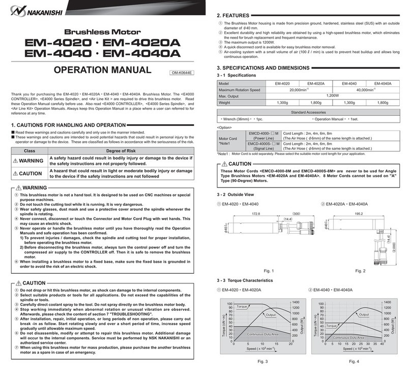
Nakanishi EM-4020A User manual

Nakanishi

Nakanishi EM-4020A User manual

Nakanishi EM20-S6000 User manual

Nakanishi

Nakanishi EM20-S6000 User manual

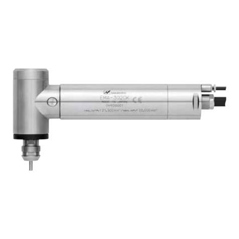
Nakanishi EMA - 3020K User manual

Nakanishi

Nakanishi EMA - 3020K User manual

Nakanishi EM-401 User manual

Nakanishi

Nakanishi EM-401 User manual

Nakanishi EM-3030T User manual

Nakanishi

Nakanishi EM-3030T User manual

Nakanishi EMS-3060K User manual

Nakanishi

Nakanishi EMS-3060K User manual

Nakanishi BMS-4020-MQL Series User manual

Nakanishi

Nakanishi BMS-4020-MQL Series User manual

Nakanishi EM-3080J User manual

Nakanishi

Nakanishi EM-3080J User manual

Nakanishi EM-3060J User manual

Nakanishi

Nakanishi EM-3060J User manual

Nakanishi EM-3060 User manual

Nakanishi

Nakanishi EM-3060 User manual

Nakanishi EM-4040 User manual

Nakanishi

Nakanishi EM-4040 User manual

Nakanishi EM-4020 User manual

Nakanishi

Nakanishi EM-4020 User manual

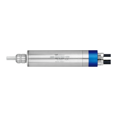
Nakanishi BMS-4040-RGD-03M User manual

Nakanishi

Nakanishi BMS-4040-RGD-03M User manual

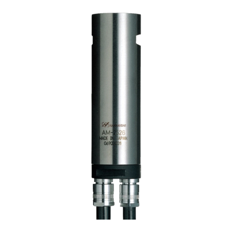
Nakanishi AM-2526 User manual

Nakanishi

Nakanishi AM-2526 User manual

Nakanishi EM-3030T-J User manual

Nakanishi

Nakanishi EM-3030T-J User manual

Nakanishi HES510 User manual

Nakanishi

Nakanishi HES510 User manual

Popular Engine manuals by other brands

Westerbeke FOUR-60 Technical manual and parts list

Westerbeke

Westerbeke FOUR-60 Technical manual and parts list

Hydro-Gear HGM-C Service and repair manual

Hydro-Gear

Hydro-Gear HGM-C Service and repair manual

Wassermann WSM-2/ 500 W user manual

Wassermann

Wassermann WSM-2/ 500 W user manual

HFE INTERNATIONAL GENPOD 70 owner's manual

HFE INTERNATIONAL

HFE INTERNATIONAL GENPOD 70 owner's manual

Eaton 1 Series Parts and Service

Eaton

Eaton 1 Series Parts and Service

Briggs & Stratton PowerBuilt Snow 120000 Series Operating & maintenance instructions

Briggs & Stratton

Briggs & Stratton PowerBuilt Snow 120000 Series Operating & maintenance instructions

Selve SP-NHK Series Operating	 instruction

Selve

Selve SP-NHK Series Operating instruction

Briggs & Stratton 310000 VERTICAL SERIES Operator's manual

Briggs & Stratton

Briggs & Stratton 310000 VERTICAL SERIES Operator's manual

CHERUBINI Plug & Play 3000 instructions

CHERUBINI

CHERUBINI Plug & Play 3000 instructions

Ramteq DV SERIES Operator's manual

Ramteq

Ramteq DV SERIES Operator's manual

Nice Era Star P Series Instructions and warnings for installation and use

Nice

Nice Era Star P Series Instructions and warnings for installation and use

Interroll RollerDrive BT100 user manual

Interroll

Interroll RollerDrive BT100 user manual

Yamaha MX-800 owner's manual

Yamaha

Yamaha MX-800 owner's manual

Zenoah G320RC owner's manual

Zenoah

Zenoah G320RC owner's manual

Mitsubishi S16R operating instructions

Mitsubishi

Mitsubishi S16R operating instructions

Farymann Diesel 15W Series Repair manual

Farymann Diesel

Farymann Diesel 15W Series Repair manual

Pentair PENTEK 76PM2-50-4 owner's manual

Pentair

Pentair PENTEK 76PM2-50-4 owner's manual

DERRICK HYPERPOOL SHAKER Maintenance & Operation Manual

DERRICK

DERRICK HYPERPOOL SHAKER Maintenance & Operation Manual

manuals.online logo
manuals.online logoBrands
  • About & Mission
  • Contact us
  • Privacy Policy
  • Terms and Conditions

Copyright 2025 Manuals.Online. All Rights Reserved.