manuals.online logo
Brands
  1. Home
  2. •
  3. Brands
  4. •
  5. NAPCO
  6. •
  7. Keypad
  8. •
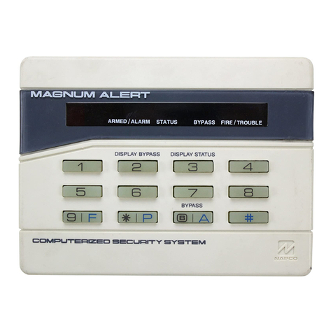
  9. NAPCO Magnum Alert RP2000LCD User manual

NAPCO Magnum Alert RP2000LCD User manual

DESCRIPTION
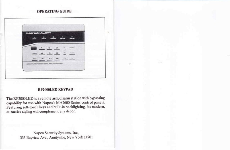
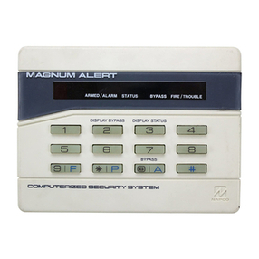
The RP2000LCD is a user-friendly backlit keypad designed
for Napco's MA2.600-Series control panels. A large al-
phanumeric liquid-crystal display (LCD) functions as a
readout for control-panel information and zone identifica-
tion, and can also serve to display messages downloaded from
a central monitoring station. The keypad functions as a
programmer as well in its secondary mode of operation. In-
stallation is quick and easy on only four wires.
fer to
and operation, and to the manual furnished with the control
panel for panel installation and dealer programming informa-
tion.
SPECIFICATIONS
Operating Voltage: 9.0-13.0Vdc (supplied by control panel)
Current: 64mA typ., normal backlighting
Dirnensions (HxWxD) : 4-3/8' x 5-7 18" x l,-Ll 16"
MOUNTING
Opening the Keypad. There are two slots along the bottom
edge of the kelpad about 1 inch from each side. To open,
insert a mediun screwdriver into either slot and push up with
a slight twisting motion to release the retainer tab. Repeat for
the other slot. Pull out at the bottom and lift off the two hooks
at the top.
When installing the rear case, be sure that the words "TOP"
and "LJPU (molded into the case) are properly oriented. The
rear case is provided with a variety of holes to accommodate
virtually any mounting situation. The four holes nearest the
center are designed to fit a double-gang box. The four slotted
holes are for mounting directly into a wall with screws suitable
for the surface material; the slots allow levelling adjustment.
The four corner holes may similnlly fe used for wall mounting,
but provide no levelling adjustment.
WIRING
Wire the kelpad to the control panel as follows:
KeypadWire
Color Code
Black o
Red (+)
Yellow
Control-Panel
Terminal
43
44
45
Green 6
NOTE: If using x soldelingiron, be careful not to splash solder
onto the kelpad circuit board or components; as damage
could result.
Remote Emergency Buttons. For remote emergency (police
panic) buttons, install momentary-contact switches to Ter-
minals 42 and43 on the control panel.
Backlighting. Backlighting requires no additional wiring. In
normal use, the kelpad is always dimly backlit. Pressing any
key will increase the brightness to facilitate code entry, but
after 30 seconds of kelpad inactiviry, brightness will again be
reduced. To disable backlighting, see JUMPER OPTIONS.
JUMPER OPTIONS
Several jumpers provide a wide variety of options. They are
conveniently located around the perimeter of the board for
easy access. To identify the location of the jumpers, refer to
the label (LA809) af|xed to the fishpaper on the back of the
board. (NOTE: Jumper C is not an option; it must be intact
at all times.)
Disable Keypad Panic. Cut Jumper A to disable the keypad
panic buftons (Police Emergency), Keys [*] and [C]. NOTE:
This will also disable the Copy Text function in the Zone-
Description Program Mode (see User's Guide, OI137).
Therefore, if disabling keypad panic, cut Jumper A after
programmin g zone descriptions.
Disable Tactile Beep. Cut Jumper B to silence the tone that
sounds whenever a keypad button is pressed.
Disable Keypad Fire. Cut Jumper D to disable the keypad fire
buttons (Fire Emergency), Keys [*] and [A].
Disable LCD Backlight. Cut Jumper W2 to disable LCD
display back lighting.
Disable Touchpad Backlight. Cut Jumpers W1 and W3 to
disable touchpad backlighting.
Kepad Assignment. Up to 7 keypads may be connected to
the panel. If more than one keypad is installed"
(a) each must be assigned its own unique keypad address
number (that is, no two keypads may be numbered alike);
(b) keypads must be numbered consecutively (that is, missing
numbers are not permitted); and
(c) only Keypad No. 1 can be used for programming.
In multiple keypad configurations, the total number of
keypads must be programmed into the contol panel in address
995. The number in address 995 must agree with the total
number of keypadsin the system, or a [KEYPAD FAIL XX]
system trouble will result.
RP2000LCD address numbers are "programmed" by selection
of the Address Jumpers, the four-block jumper strip at the
extreme lower-right corner of the board (viewed from the
inside bottom). Referring to the following table, program the
keypad address by shoning the respective pair(s) of terminals
with a jumper, as indicated by "[:]" fiumper on); ":" indicates
open Qumper off).
RP2000LCD Address Jumper
No. 321P*
L : : [:][:]
2 :[:]: [,]
3 : [:][:]:
4 [:]: : [']
5 [:]:[:]:
6 [:][:]: :
1 [:][:] [:] :
*Parking position for unused jumper(s) (located nearest the
corner).
[:] : Jumper on (shorted); : : Jumper off (open)
LCD ADJUSTMENT
The viewing angle for the LCD display is adjustable by means
of the LCD ADJUST screwdriver control on the back of the
circuit board (refer to Label LA809 affixed to the board).
Viewing the board at its normal mounting height, turn the
control clockwise or counterclockwise for optimum contrast.
TESTINGTHE KEYPAD
To test the keypad after installation, simultaneously press
Keys [*] and [3]. This will initiate a test that checks all LCD
ele ments, the sounder, and both LEDs. Repeatedly pressing
these keys will change the pattern displayed on the LCD. To
terminate the test, press the IRESET] Button.
COMPLETING THE INSTALLATION
To reassemble the keypad after installation, hang the top of
the front panel onto the hooks in the rear case and push in
firmly at the bottom until the retainer tabs snap into place. (If
difficulty is encountered, push the retainer tabs up slightly
using a screwdriver, as when removing.)
Circuit Board
Jumper Block
Front Panel
Address jumpers as viewed li'onr the inside bottom. RP2000LCD #1 is shown.
KEYPAD FUNCTIONS
Keypad functions are selected by means of the [FUNCTION] Key and executed by the [ON/OFF] Button. Repeatedly pressing the
[FUNCTIONI Key rvill scroll the display forward. In the Function Mode, the [BYPASS] Key may be used to scroll the Function
Menu backward. The l-8 available functions are scrolled in the following order:
I-DISP STATUS Displays all zones in fault condition.
2-DISP DIRECIORY Scrolls through all zones, identifying each.
3-DISPBYPASSED Scrollsthroughmanually-bypassedzones.
4-DISP FIRE STAT Displays the status of Fire Circuits I and2.
5-DISP SYS TBL Displays system trouble(s).
6-DISPALMHIST DisplaysAlarmHistory.
7-DISP SENSR ACCT Displays PIR-Zone activity.
8-ACT FAULT FIND* Activates the Fault-Find Mode.
9-ACT TELCO TEST* Tests the telephone lines (if enabled).
10-ACT BELL TEST* Activates the bell test.
11-ACT SERVICE* Activates the Service Code after arming.
12-AC'l WATCH* Activates all Day Zones simultaneously (Watch Vod6); a "W" will appear in the display.
13-ACT CHIME* Activates the Chime feature
14-ACT LOCATE* Activates the l-ocate feature.
15-ACT EXIT TIME Starts exit time without ringback.
16-ACT PROGRAM* Allows access to Program Mode. Enter Program Code to access Program Mode.
17-RST SENSR MSG Clears PIR ACTIVITY FAILURE message.
iS-nCr DOWNLOAD* Activates Manual Download.
+++**rEXlT{q+**** -- EIisThc Function Menu (or press [RESET]).
+When the panel is armed, the selected function will display as [XX-N/A WhenArmed], indicating that the function is not available
when the panel is armed.
I
i
I
I
DEAI;ER PROGRAITT II{ODE
First Enter Deater Proqram l,lode
. Setect Function 16 (ACTivate PROGRAil); press [Oll/OFFl.
. Enter Dealer Program Code,. press toN/oFFl.
To Access an Address
o Use [<- CURSoR] ard TCURSOR -
to move cursor.
o Use [UP] and tDotlNl to change
address.
. Press tREADl.
BLANX IJORDS
DOIJN COPY FRCil COPY TO READ
USER PROGRAITI UODE
To Enter User Proqram tlode
. Setect Function 16; press ION/OFFI.
. Enter Usen Program Code,' press t0N/0FFl.
To ProEram Zone Description
. Use IPRIOR] and (NExTl to setect zone.
. Use ILEFTI ard [RIGHT] to move cursor.
o Use [UP] and IDOIJNI to change entry.
. Press ISAVE] to store entry.
> fo Chanoe Data
. Use [<- CURSORI ard TCURSOR ->] to rpve cursor.
o Use [UPl and tDOl]lI to change entry.
. Press tSAVEl.
f o I ncrement/Decrement Address
. Use IPRIORI and IIEXT].
Io Exit Deater ProEram ilode
. Press IRESETI.
vvv
678
A
v
and
and ICoPY tRS{1.
tcoPY r0l.
. Left: Press
. Right: Press [r]
[*l and
To Exit User Program I,lode
. Press [RESETI.
[<- cuRsoR].
tcuRsoR ->1.
vv
9 10111213141516
CHARACTER NO,.---> 115
ADDR=PATI=
Fc,-lt-;--]t-r_-lt-l-l I
FUNCT}I UP <- CURSOR CURSOR .> TEST
FUNCT}I DX UP
tGft;lFft-;lt o I
EXIT
To copy Zone Description
. Disptay source zone; press [*J
. Disptay target zone; press [*J
. Press tSAVEl.

Other manuals for Magnum Alert RP2000LCD

1

Other NAPCO Keypad manuals

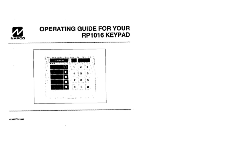
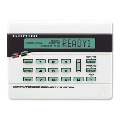
NAPCO Gemini GEM-RP2ASe2 User manual

NAPCO

NAPCO Gemini GEM-RP2ASe2 User manual

NAPCO Gemini GEM-RP1CAe2 User manual

NAPCO

NAPCO Gemini GEM-RP1CAe2 User manual

NAPCO RPXP6GT User manual

NAPCO

NAPCO RPXP6GT User manual

NAPCO GEMINI GEMC-255 User manual

NAPCO

NAPCO GEMINI GEMC-255 User manual

NAPCO Security System User manual

NAPCO

NAPCO Security System User manual

NAPCO RP1054e User manual

NAPCO

NAPCO RP1054e User manual

NAPCO MAGNUM ALERT RP3000 KEYPAD User manual

NAPCO

NAPCO MAGNUM ALERT RP3000 KEYPAD User manual

NAPCO MAGNUM ALERT RP1000E LCD KEYPAD User manual

NAPCO

NAPCO MAGNUM ALERT RP1000E LCD KEYPAD User manual

NAPCO MAGNUM ALERT RP1016E KEYPAD User manual

NAPCO

NAPCO MAGNUM ALERT RP1016E KEYPAD User manual

NAPCO RP1054e User manual

NAPCO

NAPCO RP1054e User manual

NAPCO MAGNUM ALERT RP2000 KEYPAD User manual

NAPCO

NAPCO MAGNUM ALERT RP2000 KEYPAD User manual

NAPCO Gemini GEM-RP1CAe2 User manual

NAPCO

NAPCO Gemini GEM-RP1CAe2 User manual

NAPCO Magnum Alert RP1000ELCD User manual

NAPCO

NAPCO Magnum Alert RP1000ELCD User manual

NAPCO GEM-DXRP2 User manual

NAPCO

NAPCO GEM-DXRP2 User manual

NAPCO Gemini GEM-P1632 User manual

NAPCO

NAPCO Gemini GEM-P1632 User manual

NAPCO MAGNUM ALERT RP1016E KEYPAD User manual

NAPCO

NAPCO MAGNUM ALERT RP1016E KEYPAD User manual

NAPCO iSecure ISEC-WL-KEYPAD User manual

NAPCO

NAPCO iSecure ISEC-WL-KEYPAD User manual

NAPCO GEM-RP8LCD User manual

NAPCO

NAPCO GEM-RP8LCD User manual

NAPCO Magnum Alert RP2000LCD User manual

NAPCO

NAPCO Magnum Alert RP2000LCD User manual

NAPCO GEM-RP2AS User manual

NAPCO

NAPCO GEM-RP2AS User manual

NAPCO Magnum Alert User manual

NAPCO

NAPCO Magnum Alert User manual

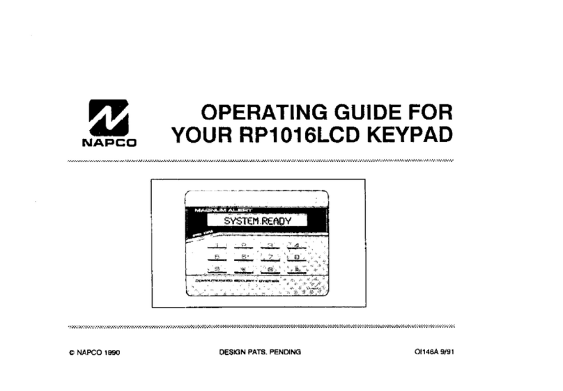
NAPCO RP1016LCD User manual

NAPCO

NAPCO RP1016LCD User manual

NAPCO Gemini GEM-K2AS User manual

NAPCO

NAPCO Gemini GEM-K2AS User manual

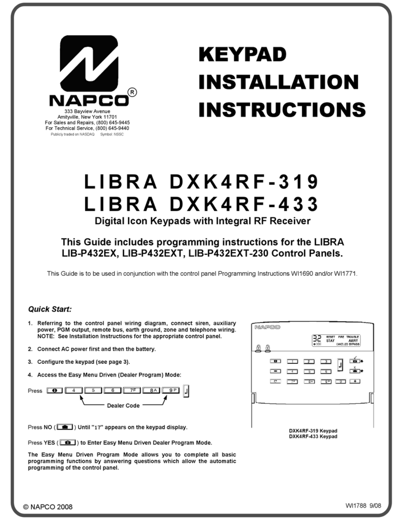
NAPCO LIBRA DXK4RF-319 User manual

NAPCO

NAPCO LIBRA DXK4RF-319 User manual

Popular Keypad manuals by other brands

Honeywell Ademco 6460S Installation and setup guide

Honeywell

Honeywell Ademco 6460S Installation and setup guide

Fleetwood WRS7200 user manual

Fleetwood

Fleetwood WRS7200 user manual

Mhouse DS1 easy instructions

Mhouse

Mhouse DS1 easy instructions

Comcast CentraLite 3400 Battery Installation

Comcast

Comcast CentraLite 3400 Battery Installation

PTI security systems VP keypad controls entry Installation and operation manual

PTI security systems

PTI security systems VP keypad controls entry Installation and operation manual

Xantech LC4KP Installation notes

Xantech

Xantech LC4KP Installation notes

Automatic Technology KPX-7V2 Quick setup guide

Automatic Technology

Automatic Technology KPX-7V2 Quick setup guide

Gecko in.k175 Aeware Installation & owner's manual

Gecko

Gecko in.k175 Aeware Installation & owner's manual

Allmatic RK3 manual

Allmatic

Allmatic RK3 manual

Proteco RT37 quick start guide

Proteco

Proteco RT37 quick start guide

Channel Vision A0125 instructions

Channel Vision

Channel Vision A0125 instructions

Chamberlain KPR2000 manual

Chamberlain

Chamberlain KPR2000 manual

AMX Novara SP-08-E-US instruction manual

AMX

AMX Novara SP-08-E-US instruction manual

Paradox Hellas S.A. SmartX KSDA quick start guide

Paradox Hellas S.A.

Paradox Hellas S.A. SmartX KSDA quick start guide

urmet domus 1068 instruction manual

urmet domus

urmet domus 1068 instruction manual

VeriFone SC 5000 Series installation guide

VeriFone

VeriFone SC 5000 Series installation guide

CNC-Step 400210 user manual

CNC-Step

CNC-Step 400210 user manual

CDVI KCINBT manual

CDVI

CDVI KCINBT manual

manuals.online logo
manuals.online logoBrands
  • About & Mission
  • Contact us
  • Privacy Policy
  • Terms and Conditions

Copyright 2025 Manuals.Online. All Rights Reserved.