NARGESA H3 User manual

INSTRUCTIONS BOOK
PRADA NARGESA, S.L
Ctra. de Garrigàs a Sant Miquel s/n · 17476 Palau de Santa Eulàlia (Girona) Spain
Tel. +34 972568085 · [email protected] · www.nargesa.com
GAS FORGE
H3

Thank you for choosing our machines
www.nargesa.com

INDEX
1. MACHINE INFORMATION ....................................................................................................... 3
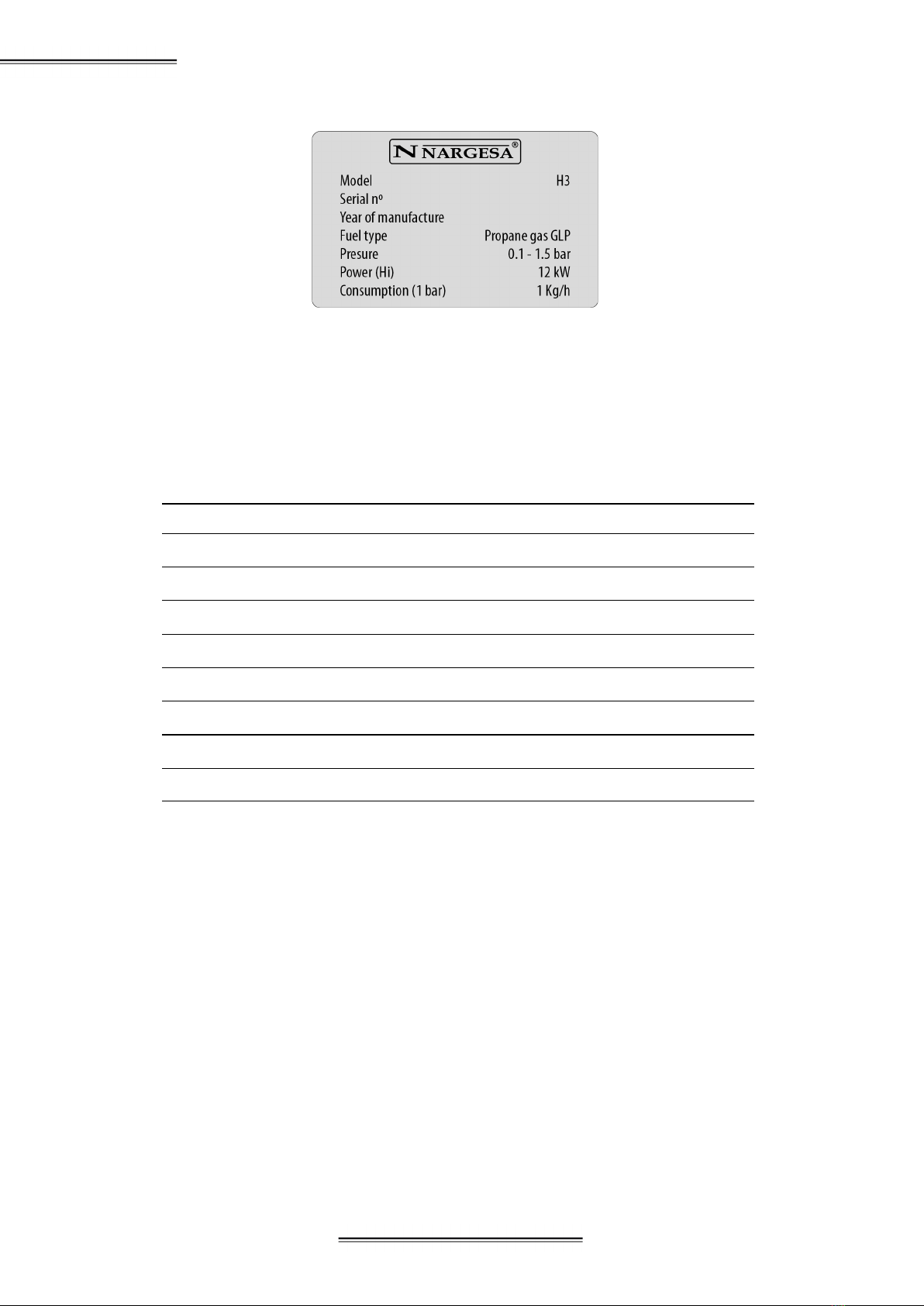
1.1. Identification of the machine …................................................................................ 3
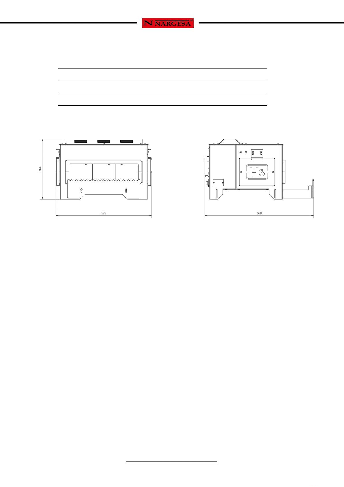
1.2. Dimensions ............................................................................................................... 3
1.3. Description of the machine …......................................................................................... 3
1.4. Fuel for the furnace ................................................................................................ 4
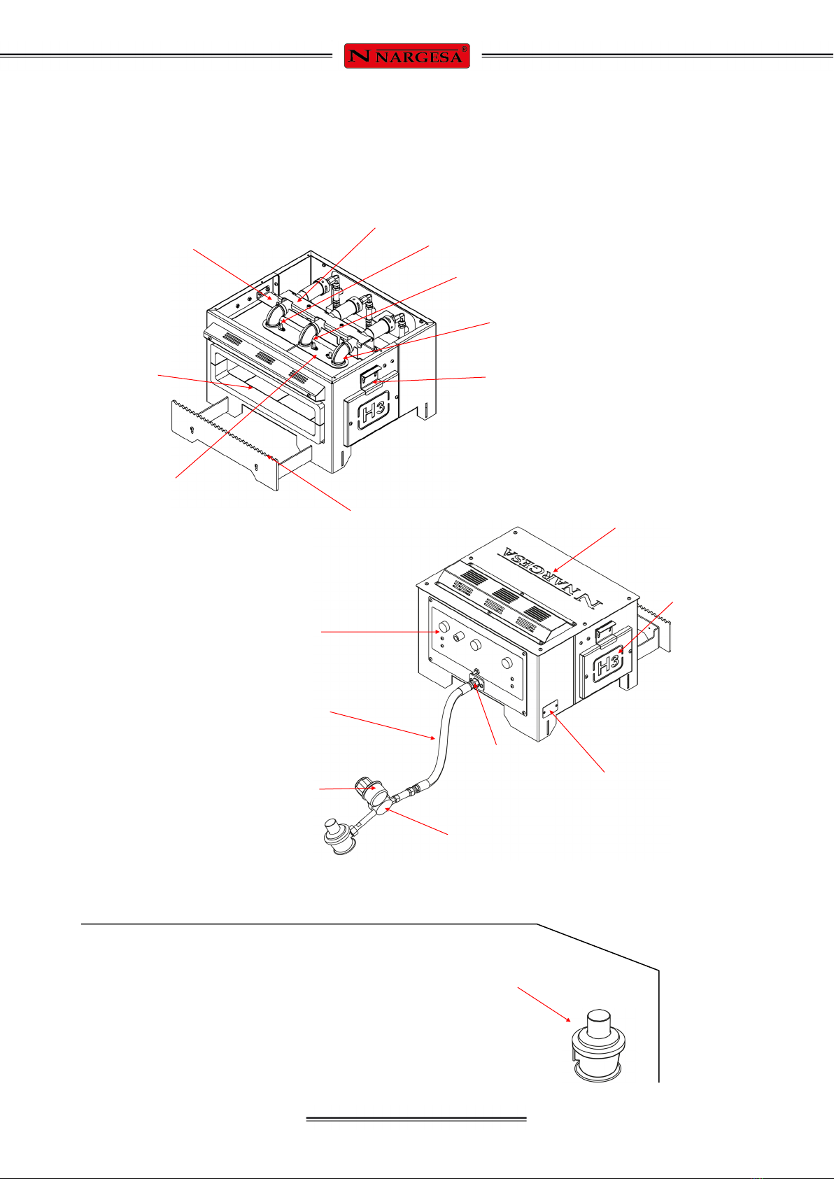
1.5. Identification of elements ....................................................................................... 5
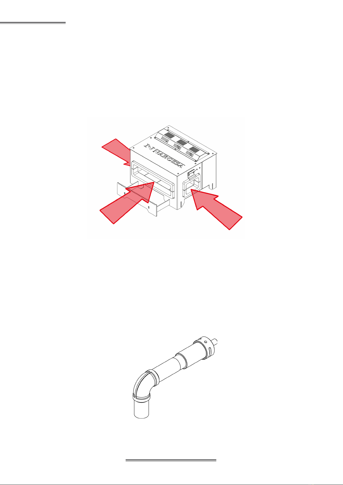
1.6. Description of elements ……......................................................................................... 6
1.6.1. Openings …………………………………………………………………………… 6
1.6.2. Burners ……..……………………………………………………………………… 6
1.6.3. Thermocouple ……………………………………………………………………..… 7
1.7. General Features ……..…………………………….……………………………………… 8
2. TRANSPORT AND STORAGE ......................................................................................... 9
2.1. Transport ...................................................................................................................... 9
2.2. Storage conditions ....................................................................................................... 9
3. MAINTENANCE ....................................................................................................................... 10
3.1. General maintenance ................................................................................................ 10
3.2. Change of the insulating material of the furnace .......................................................... 11
4. HANDLING BOOK .............................................................................................................. 16
4.1. Gas valve ……………............................................................................................... 16
4.2. Pushbuttons ................................................................................................................ 16
4.3. Pressure controller and manometer ........................................................................... 16
5. INSTALLATION AND SET UP .......................................................................................... 17
5.1. Location of th machine .............................................................................................. 17
5.2. Dimensions and work área .......................................................................................... 17
5.3. Admissible external conditions ................................................................................ 17
5.4. Set up ……………………………...……….................................................................... 18
5.5. Openings ………………………..………….................................................................... 18
5.6. Adjustment of the material support position ………………................................... 19
5.7. First set up of furnace ……………………………………………………………………. 20
5.8. Ignition of the furnace ……....................................................................................... 22
5.9. Shutdown of the furnace …..……................................................................................ 22
6. POSSIBLE BREAKDOWNS .................................................................................................... 23
7. WARNINGS ............................................................................................................................ 24
7.1. Hazard wastes ........................................................................................................... 24
7.2. Protection elements for the operator ……................................................................... 24
TECHNICAL ANNEX

- 3 -
1. MACHINE INFORMATION
1.1. Identification of the machine
1.2. Dimensions
Picture 1. External dimensions of the Furnace H3
1.3. Machine description.
The H3 Furnace is an oven designed to heat metal profiles of different thicknesses and shapes. The furnace
H3 allows us to heat parts up to a temperature of 1300ºC.
The oven is composed of three elements (supplied by Nargesa): the oven, the Gas hose and the Pressure
regulator. This type of installation will never be modified, in No Case.
The oven is equipped with three Burners for propane gas (LPG), independent.
The ignition of the oven is electronic.
The ovens designed and manufactured in Nargesa comply with the regulations in force in Spain, concerning to
the Regulation of appliances that use gas as fuel RD919 / 2006.
Brand NARGESA
Type Furnace
Model H3

- 4 -
GAS FORGE H3
IDENTIFICATION OF HAZARDS
Main hazards
Physical and chemical hazards
Specific hazards
Product effects
Adverse effects on human health
Major Synthoms
Flammable gas
Suffocating and flammable gas
Suffocating product
Inhalation may cause dizziness.
MEASURES TO FIGHT FIRES
Proper fire extintion means
Specific hazards
Special methods
Special Protection to fight against fires.
Water mist, chemical dust and carbón dioxide (CO2).
It could be lit with heat, sparks or flsmess. Steams could travel up to
the ignition source and return like flames. Keep out of container
tanks.
Remove containers from the fire zone, if this could be a riskless fact.
Spray with wáter mist the containers exposed to fire. This devide
should be remotely controlled, and so after the fire extintion. Fight
the fire aains the wind direction, whenever it is posible. Do not
extinguish fire before stopping the leak. In case the fire is intense in
loaded areas, use hoses with holders to be used remotedly. Then if
thi could not be done, just leave the área and let it burn.
In closed places, use complete protection against fire and
autonomous equipment to protect the respiratory tract.
WARNING!
Consult your supplier’s gas safety data card, before its use.
Strictly follow your supplier’s safety protocols.
COMPOSITION AND INFORMATION: PROPANE GAS G.L.P.
Chemical nature
Synonyms
Ingredients
Blend of Hydrocarbones
Gas de cocina - Gas licuado de petróleo
Propane
Butane
Ethane
Penthane
1.4. Fuel to be used with this foerge

- 5 -
1.5. Identificación de los elementos
Control panel
Burner 2
Burner 1
Side cover
Material holder
Closing
Gas inlet
fitting
Ignition
chamber
Pressure gauge
Presure control
device
Adapter
The Adapter for the gas bottle is NOT
provided along with the furnace because of
the major differences according to each
country.
The Adapter must be equipped with a male
thread 21,8 left.
Upper fixing
device for
burners
Lower fixing
device for
burners
Sparks plug
holder
Wáter hose
Upper cove
Burner 3
Information plate

- 6 -
GAS FORGE H3
1.6. Description of elements
1.6.1. Openings
The furnace has three openings:
- The front opening is the one usually used, since it is the widest.
- Side openings are used to heat longer bars. If we want to heat a larger length of bar we will open only a late-
ral opening. If we want to heat an intermediate part of the bar we will open the two lateral openings of the
oven so that the bar can pass through the inside of the oven and thus be able to heat the desired part
Picture 2. Furnace openings
1.6.2. Burners
The burners of Nargesa’s Furnaces has been manufactured by Nargesa and designed exclusively to be used
on the furnaces H1, H2 and H3.
- Type of burner: Athmospheric
- Maximum supply pressure: 1,5 Bar
- Fuel: Propane gas GLP
- Power: 4 Kw
Picture 3. Furnace burner
Side opening
Front opening
Side opening

- 7 -
1.6.3. Thermocouple
The thermocouple is the sensor to measure the temperature. It consists of two different metals, joined at one
end. When the union of the two metals is heated or cooled, it produces a voltage proportional to the tempera-
tura which causes the safety valve to open or close.
The thermocouple safety valve consists of two parts: The valve and the thermocouple
The valve is equipped with the Thermocouple pushbutton for ignition of the furnace.
In the process of ignition of the furnace we press this button to allow the passage of gas. When the thermo-
couple gets enough temperature, we will release this pushbutton and the gas will continue to pass through the
valve. This valve will remain open while the oven is in operation and the thermocouple will keep the working
temperature.
Once the oven is switched off, and in a time interval of less than 2 minutes, the thermocouple cools and stops
acting on the closing safety valve, thus preventing the passage of gas
Picture 4. Thermocouple set
Thermocouple
Thermocouple valve

- 8 -
GAS FORGE H3
Picture 5. Information plate
1.7. Main features
Dimensions of combustion chamber 464x240x100 mm
Maximum temperature 1300 ºC
Nr of burners 3
Type of fuel Propane gas (GLP)
Adjustable working pressure 0.1-1.5 bar
Power (Hi) 12 kW
Gas intake as 1 per bar 1 Kg/h
External dimensions 500x580x365 mm
Weight 50 Kg

- 9 -
WARNING:
In order to move the gadget it is necessary that all burners a re OFF and wait 24 hours to make sure the
isolating material is at room temperature.
2. TRANSPORT AND STORAGE
2.1. Transport
Carrying of the furnace must be done by two people, holding it by the lower side of it and lifting it with both
hands.
Do not transport the furnace in any other way since it could be damaged.
Picture 6. Transport of the machine
2.2. Storage conditions
The furnace cannot be stowed in a place that does not meet the following requirememts:
- Humidity between 30% and 95%
- Temperaturre from -25 to 55ºC or 75ºC pfor periods not exceeding 24 hours 24h (keep in mind these
temperaturas are for storage conditions)
- Do not pile machines or any other objects on tp of it.
- Do not dismantle for stowing

- 10 -
GAS FORGE H3
WARNING:
To proceed with the maintenance of the oven it is necessary to turn off the Burners and wait 24 hours to
ensure that all the components are at ambient temperature.
3. MAINTENANCE
3.1. General Maintenance
- It is recommended to keep the Combustion chamber clean, as far as possible, to ensure proper operation
and thus prolong the useful life of the insulating material.
- It is recommended to check the status of the thermocouple, the ignition device, the gas valve, the regulator
and the non-return valve. If any of these elements suffers any type of deterioration, contact the Nargesa
technical service.
- It is required the replacement of the thermocouple, the ignition device, the gas valve, the regulator and the
non-return valve every 5 years. It is advisable that the technical service of Nargesa make this substitution.
- It is recommended to check periodically the condition of the isolating material to ensure good insulation of
the Combustion chamber with the outside of the oven. In case the isolating material is degraded, it can be
damaged immediately and irreparable damage will be caused to the metallic enclosure.
- It is recommended to replace the insulating material every 1000 hours of operation.
Picture 7. Insolating kit

- 11 -
3.2. Change of the insulating material of the oven
To remove the insulating material from the oven we will follow the following instructions:
1. Disconnect the gas bottle from the oven. 2. Disconnect the Gas hose from the Inlet fitting
3. Remove the Upper cover by unscrewing the
six bolts.
4. Remove the Upper setting of the burners
WARNING:
To proceed with the change of insulating material it is necessary to turn off the Burners and wait 24 hours to
ensure that the insulating material is at room temperature

- 12 -
GAS FORGE H3
5. Remove the thermocouple and the spark
plugs by pull away the three bolts
6. Take off the 4 bolts and nuts that hold the
Control Panel. Remove the Control panel, the
thermocouple and the spark plugs
7. Remove the two Burners and the Spark
plugs holders
8. Dismantle the Lower fixing of the burners by
unscrewing the four bolts and the four nuts that
hold it.
9. Remove the Side doors following the
instructions on Section 5.5
10. Take off the insulation upper plates.

- 13 -
11. Remove the rear insulation panels 12. Remove the front holders of the upper plate
13. Remove the lower insulation 14. Slide the lower insulation towrads the back
part of the furnace and remove them by the upper
side.
15. Remove the side insulations 16. Remove the front insulations

- 14 -
GAS FORGE H3
We will use this process in reverse order to do the placement of the insulation:
5. Place the rear insulation
4. Place the front holders of the upper plate3. Place the lower insulation by the upper/ rear
side of the furnace and slide them towards the
front part.
2. Place the side insulation1. Place the front insulation
6. Put the insulation upper plates

- 15 -
11. Place the Upper cover by fixing the 6 bolts
10. Mount the Upper fixer of the burners9. Place the Control panel, the thermocouple
and the spark plugs by fixing the bolts and
nuts.
8. Place the Spark plug holder and the three
burners adjusting the Lower burner fixer so
that the end of the Burner is aligned with the
7. Place the Side doors. Assemble the Lower
fastener of the burners by tightening the
four screws and the four nuts that hold it
12. Connect the Gas Hose to the Inlet racor

- 16 -
GAS FORGE H3
Electronic switching Gas valve 1 Gas valve 2 Gas valve 3
4. HANDLING MANUAL
We have a Control panel which will allow us to control the performance of the furnace H3 and which will
enable us to maintain complete control of the m¡achine in a simple and intuitive way.
4.1. Gas valve
The Control panel has got three valve for the opening of the gas entrance to the Burners. These valves are
marked with numbers 1, 2 and 3 the operator controls them in order to obtain more on less gas flow.
4.2. Pushbuttons
There are two puhbuttons in the Control panel:
- The pushbutton for Electronic switching is the one that activates the spark plug and generates the spark to
light up the Burner.
- The Thermocouple pushbutton is the one that opens the valve the get the thermocouple activated. This
valve opens the path to the Gas valves (1, 2, 3)
4.3. Pressure regulator and manometer
The Pressure regulator allows us to control the working pressure between 0,1 and 1,5 bar, Nargesa suggests
to work at a pressure from 0,2 to 1 bar. The Manometer will indicate the pressure value on the furnace circuit.
Thermocouple
pushbutton

- 17 -
5. INSTALLATION AND SET UP
5.1. Machine location
The am is to locate the furnace properly to avoid having to move it; otherwise, the user must follow the guideli-
nes described in the transport section (nº2). It should be placed on a smooth and levelled surface to avoid any
movement of it during the positioning of the profiles.
5.2. Dimensions y work area
When the furnace is placed, its dimensions, the safety zone, the work area of the operator and the possible
lengths of the workpiece will be taken into account.
Safety zone: We will place the furnace in a zone free of elements and objects, following the indications of the
following figure.
The oven will be installed in accordance with the regulations in force and will be used only in sufficiently venti-
lated places.
The oven can be used by a single operator, which must be work frontally or laterally to the machine to be able
to handle the piece safely.
Before starting the heating of the pieces, with the Burners off, the operator will adjust the material support,
adapting it to the material profile and its length, as indicated in section 5.6.
Picture 8. Safety zone
5.3. Admissible outside conditions
- Normal temperatura between +5 and +40ºC without exceeding an average temperature of +35ºC during 24h.
- Relative humidity betwee 30% and 95% without condensation.

- 18 -
GAS FORGE H3
The Pressure Regulator and Gas Hose supplied by Nargesa will always be used
5.4. Setting up
Before putting the furnace into operation:
- Inserting the automatic ignition battery.
- Connect the Pressure regulator to an Adapter for the gas cylinder. This adapter is not supplied with the fur-
nace , as this element is different in each country.
- Verify that the maximum gas inlet pressure is less than 25 bars.
- Connect the Adapter to a LPG propane gas cylinder
5.5. Openings
There are two side openings to work with longer materials.
To remove the Doors, move the Lock up and pull the Door out of position. Leave the Closure in its original
position.
To place the Side door, move the Latch upwards and place the Door in the lateral opening, press until it stops
and lower the Latch to its original position.
WARNING:
To manipulate the Side doors it is necessary to turn off the Burners and wait 24 hours
to make sure that the insulating material is at room temperature
1. Unscrew the Automatic
ignition button ( ) located on
the control panel.
3. Tap tight the Automatic
ignition button.
2. Insert the battery into the hole
so that its positive end is on the
outside.

- 19 -
5.6. Adjustment of the material support position
The oven is equipped with a Material holder, this support serves to hold the material while warming up.
The support point of the material can be regulated by moving the support. The point of support must be
adjusted according to the length of the material. For material lengths bigger than 800mm, use an external
support.
The Material holder can be placed in any of the three Openings.
Picture 9. Support of material
Table of contents
Other NARGESA Industrial Equipment manuals

NARGESA
NARGESA H1 User manual

NARGESA
NARGESA MX340G User manual

NARGESA
NARGESA PC16 User manual

NARGESA
NARGESA NOA60 Owner's manual

NARGESA
NARGESA PP200 User manual

NARGESA
NARGESA PP200CNC User manual

NARGESA
NARGESA NOA60 User manual

NARGESA
NARGESA MX700 User manual

NARGESA
NARGESA NF70 User manual

NARGESA
NARGESA NF70 User manual
Popular Industrial Equipment manuals by other brands

TUFLOC
TUFLOC TufBox Base installation instructions

Omron
Omron MX-Z2000H-V1 Series user manual

schmersal
schmersal AZM201Z-I2-SK-T-1P2PW Instructions for operation

T&S
T&S B-0968 Installation and maintenance instructions

TLV
TLV JL9X instruction manual

Browning
Browning Torq/Gard Installation, operation and maintenance instructions