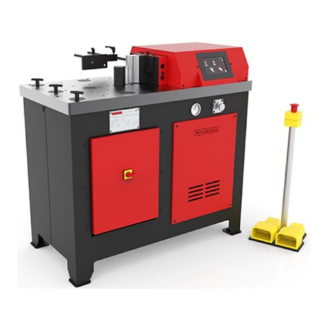
NARGESA PP200 User manual

INSTRUCTIONS BOOK
PRADA NARGESA, S.L
Ctra. de Garrigàs a Sant Miquel s/n · 17476 Palau de Santa Eulàlia (Girona) SPAIN
Tel. +34 972568085 · [email protected] · www.nargesa.com
HORIZONTAL PRESS BRAKE
PP200

Thank you for choosing our machines
www.nargesa.com

INSTRUCTIONS BOOK HORIZONTAL PRESS BRAKE PP200 2
3
3
3
3
4
5
5
6
6
6
7
7
7
8
8
8
9
9
10
10
10
11
12
13
13
14
14
15
16
INDEX
1. CHARACTERISTICS OF THE MACHINE ...............................................................................
1.1. Machine identification ..................................................................................................
1.2. General dimensions ....................................................................................................
1.3. Machine description ....................................................................................................
1.4. Identification of components .......................................................................................
1.5. General characteristics ...............................................................................................
1.6. Identification of protective panels ................................................................................
2. TRANSPORT AND STORAGE ...............................................................................................
2.1. Transport .....................................................................................................................
2.2. Storage conditions ......................................................................................................
3. MAINTENANCE AND CLEANING ..........................................................................................
3.1. Hydraulic maintenance ................................................................................................
3.2. Cleaning ......................................................................................................................
4. INSTALLATION AND START UP ...........................................................................................
4.1. Placement ...................................................................................................................
4.2. Work area ....................................................................................................................
4.3. Acceptable external conditions ...................................................................................
4.4. Electrical connection ...................................................................................................
5. INSTRUCTIONS FOR USE .....................................................................................................
5.1. Description of the control panel ...................................................................................
5.2. Start up ........................................................................................................................
5.3. Displacement adjustments ..........................................................................................
5.4. Adjustment of the working strength .............................................................................
5.5. Manual mode ..............................................................................................................
5.6. Automatic mode ..........................................................................................................
6. FAULT FINDING ......................................................................................................................
6.1. Electrical faults ............................................................................................................
7. CAUTION .................................................................................................................................
8. TOOLING .................................................................................................................................
TECHNICAL ANNEX

INSTRUCTIONS BOOK HORIZONTAL PRESS BRAKE PP200 3
1. CHARACTERISTICS OF THE MACHINE
1.1. Machine Identification
1.2. General Dimensions
Figure 1. External Dimensions of the Horizontal Press Brake
1.3. Machine description
The versatility of the Horizontal Press Brake NARGESA PP200 allows us to carry out a large number of
forging parts and operations depending on the need. This machine curves, cuts, shapes etc... depending
on the type of accessory used.
A sample of the different types of accessories that can be applied is listed at the end of this manual.
Trademark Nargesa
Type Horizontal Press Brake
Model PP200

INSTRUCTIONS BOOK HORIZONTAL PRESS BRAKE PP200 4
Electrical panel
Workbench
Buffer Upper panel
Position
regulator
Pressure
regulator
Pressure
gauge
Side panel
Nameplate
Headstock
Stabilising
rivets
Pedals
Shelving
1.4. Identification of Components
Figure 2. Names and positions of components
Figure 3. Nameplate

INSTRUCTIONS BOOK HORIZONTAL PRESS BRAKE PP200 5
Panel accessing
hydraulic system
Upper panel
1.5. General characteristics
1.6. Identification of Protective panels
Figure 4. Position of security panels
It is PROHIBITED to work without the protective panels in place and should only be removed in
case of a breakdown (if necessary) and always with the machine in the OFF position.
Electric motor 2.2 Kw / 3CV at 1400 r.p.m.
Electrical power 230/400 V three-phased volts
Intensity 9/5 A
Hydraulic pressure 215 Kg/cm2
Hydraulic pump 7.5 litres/minute
Tank 27 litres
Weight 625 Kg.
Maximum displacement 250 mm
Working strength 20.000 Kg (200 KN)

INSTRUCTIONS BOOK HORIZONTAL PRESS BRAKE PP200 6
2. TRANSPORT AND STORAGE
2.1. Transport
The machine must be transported in an upright position using a forklift or a pallet jack fixed to the base of
the machine (pre-designed for this purpose).
Please take into account the risk of the machine tipping over.
Figure 5. Transport of the machine
2.2. Storage conditions
• Humidity between 30% and 95% without condensation.
• Temperature between 15ºC and 55ºC.
• Don not place articles on top of the machine.
• Do not disassemble the machine for storing.

INSTRUCTIONS BOOK HORIZONTAL PRESS BRAKE PP200 7
1
2
3. MAINTENANCE AND CLEANING
There are two aspects to take in to account with respect to the maintenance and cleaning of the Horizontal
Press Brake NARGESA PP200, these are:
- Hydraulic Maintenance
- Cleaning maintenace
3.1. Hydraulic maintenance
As the Horizontal Press Brake NARGESA PP200 possesses a hydraulic mechanism, it is necessary to
periodically check the oil level tank. The machine is equipped with a low oil indicator (1) which permits us to
observe the level of oil. This should be carried out with the machine on the standby and off position.
Figure 7. Positions of the Hydraulic maintenance elements
If the level is low it should be filled with hydraulic oil HM68 through the tank cap (2) until it is visible in the
low oil indicator (1) (approximately half way up the indicator). This level should be checked once every
three months.
3.2. Cleaning
The daily usage of the Horizontal Press Brake NARGESA PP200 can generate metallic waste such as
(slag, shavings, etc.) which can damage the running of the machine. We recommend that the machine be
cleaned, especially the work area, at the end of each day.

INSTRUCTIONS BOOK HORIZONTAL PRESS BRAKE PP200 8
4. INSTALLATION AND START UP
4.1. Placement
The Horizontal Press Brake NARGESA PP200 should be placed on a flat, level surface. It is possible to
secure it to the floor using the pre-made holes on the base of the machine for this purpose.
Figure 8. Anchor points
4.2. Work Area
Given the versatility of the Horizontal Press Brake NARGESA PP200 it is important to have the necessary
working space, especially at the permiters of the machine, taking into account that the maximum or
minimum limitations will depend on the accessory used. The operator should stand behind the machine
together with the pedals.
Figure 9. Work area

INSTRUCTIONS BOOK HORIZONTAL PRESS BRAKE PP200 9
4.3. Acceptable external conditions
The working conditions of the machine can fluctuate between +5ºC and +50ºC being the maximum
temperature and not exceeding an average temperature of +45º in a 24 hour period.
The humidity can fluctuate between 30% and 90% without condensation.
4.4. Electrical connection
The Horizontal Press Brake NARGESA PP200 is designed to be connected to a
three-phase power supply of 230/400 volts at 50/60Hz.
Once connected ensure that the electric motor is turning in the correct direction
(the direction indicated on the sticker placed on the motor) if this is not so, one of the phases must be
relocated.
NOTE: If there is a change in voltage it will be necessary to modify the protectors of the electric
motor following the table below:
Star figure
(predetermined)
For 400V
Triangular figure
For 230V
VOLTAGE MOTOR GUARD CONTACTOR
230 V 7 - 10 A
400 V 4 - 6 A

INSTRUCTIONS BOOK HORIZONTAL PRESS BRAKE PP200 10
Start
Counter to cero
Stop
Manual mode
ESC
Automatic mode
Main switch
Voltage indicator
Restart indicatos
ON indicator
5. INSTRUCTIONS FOR USE
The Horizontal Press Brake NARGESA PP200 has two working modes:
• Step by step mode
• Normal or discontinued mode
Before explaining the working modes, we will describe the different components and characteristics of the
Horizontal Press Brake NARGESA PP200.
5.1. Description of the control panel
The Electrical control panel incorporating the different controls can be found on the side of the machine.
(see figure 10 below)
Figure 10. Control Panel
5.2. Start up
To start up the Horizontal Press Brake NARGESA PP200 first you must connect it to the mains electricity
supply inidicated in paragraph. 4.4. Once connected press the main switch and the voltage and alarm
indicators will appear. Unblock the emergency stop button, in case it is activicated, press the restart button.
The alarm indicator will now extinguish. Press the ON button.
Emergency stop button
Restart button
Alarm indicator

INSTRUCTIONS BOOK HORIZONTAL PRESS BRAKE PP200 11
Forward stop point knob (1) Backward stop point knob (2)
5.3. Displacement adjustments
As aforementioned the Horizontal Pree Brake NARGESA PP200 has a maximum displacement of 250mm,
this displacement may be excessive depending on the accessory used. To control the displacement, the
PP200 has a regulation panel on its side for the purpose of adjusting it.
Figure 11. Regulation panel
To regulate the position, the selected working mode must be taken into account: manual or automatic.
1. Manual mode:
Moving the limits of the displacement of the headstock forwards or backwards, the machine will move to
the position indicated by the stop knob.
2. Automatic mode:
Standby position: moving the backward stop point knob (2), the machine will move until it reaches the
indicated position automatically.
Setting the forward stop point has two options:
The first option is to move the forward stop point knob (1) to the required position and verify the position
using the pedals to advance until the machine reaches the indicated place.
The second option is, once the machine has reached the indicated position, keeping pressure on the pedal
move the forward stop point knob to the desired position, once set the machine will go forward until the
position indicated.
In this way we are able to carry out a more precise adjustment of the final position, releasing pedal will
regain the original position.
Once adjusted we advise you to run a trial cycle (without material) to verify the positions and if necessary to
repeat the operation.

INSTRUCTIONS BOOK HORIZONTAL PRESS BRAKE PP200 12
Pressure regulator Pressure gauge
5.4. Adjustment of the working strength
The Horizontal Press Brake NARGESA PP200 supplies 20,000Kg of strength.
This amount of power may be excessive depending on the type of work to be carried out. The PP200
incorporates a pressure regulatory system to allow us to decrease the strength of the machine.
Figure 12. Elements for the regulation of strength
To decrease the strength of the PP200 follow the procedure described below:
1. Place a resistant object over the headstock to act as a buffer.
2. Loosen the screw which blocks the pressure regulator.
3. Press the pedal so that the PP200 buffers the resistant object.
4. When buffered turn the pressure regulator towards the minus symbol. The pressure gauge,
situated to its right, will indicate a decrease in pressure value. When the ideal pressure is obtained release
the pedal.
5. Tighten the screw on the pressure regulator.
Now the PP200 is adjusted to use with less strength. Move the headstock back and remove the resistant
object.
To increase strength carry out the same procedure moving the pressure indicator to the plus symbol.
NOTE: Remember after decreasing the strength the PP200 will not be using its maximum power.

INSTRUCTIONS BOOK HORIZONTAL PRESS BRAKE PP200 13
5.5. Manual mode
The manual mode is the mode of work of the machine which is used to adjust and centre the different
accessories and shapes as it allows us total control over the movements of the machine.
The manual mode functions by pressing or releasing the pedals to move forwards or backwards. If the
pedal is releasesd the machine will stop in that position, the machine will also stop at the end of its
displacement.
5.6. Automatic mode
The automatic mode is the usual production mode.
In order to select the automatic performance mode, we press the “Automatic” key and the machine will ask
if we want to go into the “Automatic Mode”. We press the automatic key again in order to confirm.
The automatic mode functions by maintaining the pedal pressed until the machine reaches the point
indicated by the forward stop point knob, when the pedal is released the machine will reverse the
maneuvre until it reaches the standby position. If the pedal is released before end of trajectory the
machine will also reverse the maneuvre returning it to the standby position.
NOTE: The machine in use can be seen on our website: www.nargesa.com
or on our Youtube channel, link:
https://www.youtube.com/watch?v=TEPEwYjt08s

INSTRUCTIONS BOOK HORIZONTAL PRESS BRAKE PP200 14
6. FAULT FINDING
6.1. Electrical faults
Due to the daily usage of the Horizontal Press Brake NARGESA PP200 faults may arise. The following list
of occurrences and their remedies should help you identify and solve most problems.
NOTE: In case of repeated problems please contact our technical services at NARGESA.
Problem Cause Solution
Indicators lamps
do not light up
No electrical supply
Ensure that the machine is
connected to the main electrical
supply
Insuffficient power Verify that there is sufficient power
The breaker switch of the control
panel is discativated
Restart breaker switch on the
control panel
The protection fuse is blown Replace the fuse
Electric Motor
malfunction
The breaker switch of the motor is
disactivated Restart breaker switch of the motor
Insifficient power Verify the power input
Emergency stop button activated Rotate emergency stop button and
restart machine
Fault in motor guard contactor Contact technical services

INSTRUCTIONS BOOK HORIZONTAL PRESS BRAKE PP200 15
7. CAUTION
- Do not manipulate any components of the machine while functioning.
- Do not use the machine for any other purpose that those described in this manual.
- Use gloves to manipulate the components of the machine during the process of work.
- Use officially approved protective glasses and boots.
- Firmly hold the material during manipulation.
- Do not work the machine without the protective panels in place.
NARGESA SL does not take responsibility for any accidents caused
by the negligence of the operator.

INSTRUCTIONS BOOK HORIZONTAL PRESS BRAKE PP200 16
8. TOOLING
Folding die at 150 mm. · V16, 22 35 50 mm. PP200
Folding or bending die up to 150mm with 4 openings
(16, 22, 35, 50mm) and a punch of 88º. This multi-V
die allows 1mm up to 8mm sheet to be folded. The
70mm outer die¡ameter punch allows to make
completely closed shapes to a minimum of 75mm
inner wing.
V 16: Sheet from 1 to 3mm
V 22: Sheet from 2 to 4mm
V 35: Sheet from 3 to 6mm
V 50: Sheet from 4 to 8mm
Max. Folding length: 150mm
Max. Folding thickness: 8mm
Standard tooling provided along with the machine.

INSTRUCTIONS BOOK HORIZONTAL PRESS BRAKE PP200 17
Flat bar and metal sheet cutting die up to 100mm
through a maximum thickness of 10mm in mild steel.
Punch holder for all kind of punches for Promecam
bending or folding press.
Compatible with any Promecam punch.
Flat bar cutting tooling 100x10 mm. PP200 · REF. 140-16-01-00014
Max. Cutting length Max. Cutting thickness Weight
100 mm 10 mm 23 Kg
Promecam punch holder PP200 · REF. 140-16-01-00023
Max. Folding length Weight
150 mm 14 Kg
Die to form rings or English banister railing, used as
ornamental piece in forging railings, gates, fences,
etc... for bars bonding. For other sizes and
applications consult the manufacturer
Ring forming · REF. 140-16-01-00003
Max. width Thickness Outer sizes Weight
50 mm 6 mm 90 mm 9.3 Kg
Punch-holder die, compatible with our NARGESA
brand punches.
Punching die · REF. 140-16-01-00022
Round Square Rectangular Oval Weight
Max. Punching capacity 50 mm 35 mm 25x43 mm 25x50 mm 52 Kg

INSTRUCTIONS BOOK HORIZONTAL PRESS BRAKE PP200 18
Special punches
Promecam punches of different shapes to bend and manufacture complex part. There are a lot more shapes, please
consult the manufacturer.
Folding Punch D70 30º
REF: 140-16-01-00025
Max. Folding length: 100mm
Punch degrees: 30º
Punch diameter: 70mm
Folding Punch D40 80º
REF: 140-16-01-00026
Max. Folding length: 60mm
Punch degrees: 80º
Punch diameter: 40mm
Folding Punch D22 80º
REF: 140-16-01-00027
Max. Folding length: 60mm
Punch degrees: 80º
Punch diameter: 22mm
Weight: 3Kg each unit approximately
Folding punches to bend special pieces of small sizes or folded up to 30º.
Promecam punches
Punch Promecam PS.135.85.R08 PP20
REF: 140-16-01-00030
Folding length: 150mm
Weight: 3,2 Kg.
Punch Promecam P.95.35.R5 PP200
REF: 140-16-01-00031
Folding length: 142mm
Weight: 2,3Kg.
Punch Promecam PS.134.30.R08 PP200
REF: 140-16-01-00032
Folding length: 150mm
Weight: 2,7Kg.

INSTRUCTIONS BOOK HORIZONTAL PRESS BRAKE PP200 19
Promecam dies of diferent openings to fold sheets, flat bars or thicker plate sections up to 15mm. in order to fold even
thicker sizes, ask the manufacture.
Dies to fold thick metal sheet PP200
Die to form cold forging balusters for grills, gates,
fences, handrails, etc... For other shapes or
capacities, request the manufacturer.
Baluster forming die 01 · REF. 140-16-01-00001
Flat bar size Die length Weight
16x6 mm 656 mm 21 Kg
Die to form cold forging balusters for grills, gates,
fences, handrails, etc... For other shapes or
capacities, request the manufacturer.
Baluster forming die 04 · REF. 140-16-01-00004
Square sizes Die length Weight
12 mm 600 mm 20,5 Kg
Folding die T80.25.35 PP200
REF. 140-16-01-00036
Folding length: 150mm
Thickness: From 1,5 to 5mm Weight: 4Kg
Folding die M75-85-63 PP200
REF: 140-16-01-00033
Folding length: 150mm
Thickness: From 5 to 10mm Weight: 5Kg.
Folding die M80-85-80 PP200
REF: 140-16-01-00034
Folding length: 150mm
Thickness: From 6 to 12mm Weight: 6Kg.
Folding die M95-80-100 PP200
REF: 140-16-01-00035
Folding length: 150mm
Thickness: From 8 to 15mm Weight: 9Kg
Table of contents
Other NARGESA Industrial Equipment manuals

NARGESA
NARGESA PP200CNC User manual

NARGESA
NARGESA H1 User manual

NARGESA
NARGESA PC16 User manual

NARGESA
NARGESA NOA60 User manual

NARGESA
NARGESA MX340G User manual

NARGESA
NARGESA MX700 User manual

NARGESA
NARGESA BM25 User manual

NARGESA
NARGESA NOA60 User manual

NARGESA
NARGESA NOA60 Owner's manual

NARGESA
NARGESA MX700 User manual
Popular Industrial Equipment manuals by other brands

Nordco
Nordco C Installation, operation and maintenance manual

Bosch
Bosch Rexroth MTA 200 Planning Manual

SCHUNK
SCHUNK SPG 100 Assembly and operational manual

ABB
ABB PowerCube PB/F Installation and service instructions

OMCA
OMCA SMV 910 Use and maintenance manual

MAGUIRE
MAGUIRE Weigh Scale Blender Installation operation & maintenance