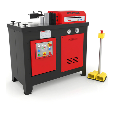
NARGESA PP200CNC User manual

INSTRUCTIONS BOOK
PRADA NARGESA, S.L
Ctra. de Garrigàs a Sant Miquel s/n · 17476 Palau de Santa Eulàlia (Girona) SPAIN
Tel. +34 972568085 · [email protected] · www.nargesa.com
HORIZONTAL PRESS BRAKE
PP200CNC
NS: 2022-531

Thank you for choosing our machines
www.nargesa.com

INDEX
1. CHARACTERISTICS OF THE MACHINE ............................................................................... 3
1.1. Machine identification .................................................................................................. 3
1.2. General dimensions .................................................................................................... 3
1.3. Machine description .................................................................................................... 3
1.4. Identification of components ....................................................................................... 4
1.5. General characteristics ............................................................................................... 5
1.6. Identification of protective panels ................................................................................ 5
2. TRANSPORT AND STORAGE ............................................................................................... 6
2.1. Transport ..................................................................................................................... 6
2.2. Storage conditions ......................................................................................................... 6
3. MAINTENANCE AND CLEANING .......................................................................................... 7
3.1. Hydraulic maintenance ................................................................................................ 7
3.2. Cleaning ...................................................................................................................... 7
4. INSTALLATION AND START UP ........................................................................................... 8
4.1. Placement ................................................................................................................... 8
4.2. Work area .................................................................................................................... 8
4.3. Acceptable external conditions ................................................................................... 9
4.4. Electrical connection ..................................................................................................... 9
5. START MENU ......................................................................................................................... 10
6. PUNCHING …………………..................................................................................................... 11
7. FOLDING ................................................................................................................................. 14
8. SHEARING .............................................................................................................................. 21
9. MANUAL POSITIONING MODE .............................................................................................. 23
10. MENU ...................................................................................................................................... 25
10.1. Remote assistance .................................................................................................... 25
10.2. Importing/exporting parameters, materials and programs ........................................ 26
10.3. Touch screen calibration ........................................................................................... 27
10.4. Tool Management ……………………………………..………………………………….. 28
10.4.1. Punching tools ……………………………….………………….…………..…… 29
10.4.2. Bending tools ………………………………….…………………………………. 31
10.4.3. Cutting tools ……………………...……………………………………………… 35
11. ADJUSTMENT OF THE WORKING STRENGHT ................................................................ 36
12. FAULT FINDING ................................................................................................................... 37
12.1. Electrical faults .......................................................................................................... 37
13. CAUTION ............................................................................................................................... 38
14. TOOLING ............................................................................................................................... 39
TECHNICAL ANNEX
TECHNICAL FEATURES - TOOLING
- 3 -
1. CHARACTERISTICS OF THE MACHINE
1.1. Machine Identification
1.2. General Dimensions
Figure 1. External Dimensions of the Horizontal Press Brake
1.3. Machine description
The versatility of the Horizontal Press Brake NARGESA PP200CNC allows us to carry out a large number
of forging parts and operations depending on the need. This machine curves, cuts, shapes etc... depending
on the type of accessory used.
A sample of the different types of accessories that can be applied is listed at the end of this manual.
Trademark Nargesa
Type Horizontal Press Brake
Model PP200CNC

- 4 -
HORIZONTAL PRESS BRAKE PP200CNC
1.4. Identification of Components
Figure 2. Names and positions of components
Figure 3. Nameplate
Electrical panel
Workbench
Buffer Upper panel
Control
panel CNC
Pressure
regulator
Pressure
gauge
Side panel
Nameplate
Headstock
Stabilising
rivets
Pedals
Shelving

- 5 -
1.5. General characteristics
1.6. Identification of Protective panels
Figure 4. Position of security panels
Panel accessing
hydraulic system
Upper panel
It is PROHIBITED to work without the protective panels in place and should only be removed in
case of a breakdown (if necessary) and always with the machine in the OFF position.
Electric motor 2.2 Kw / 3CV at 1400 r.p.m.
Electrical power 230/400V Three-Phase 50/60 Hz
230V Single-Phase 50/60 Hz
Intensity 9/5 A
Hydraulic pressure 215 Kg/cm2
Hydraulic pump 7.5 litres/minute
Tank 27 litres
Maximum displacement 250 mm
Working strength 20.000 Kg (200 KN)
Dimensions 660x1180x1130 mm
Weight 665 Kg.

- 6 -
HORIZONTAL PRESS BRAKE PP200CNC
2. TRANSPORT AND STORAGE
2.1. Transport
The machine must be transported in an upright position using a forklift or a pallet jack fixed to the base of
the machine (pre-designed for this purpose).
Please take into account the risk of the machine tipping over.
Figure 5. Transport of the machine
2.2. Storage conditions
• Humidity between 30% and 95% without condensation.
• Temperature between 15ºC and 55ºC.
• Don not place articles on top of the machine.
• Do not disassemble the machine for storing.

- 7 -
3. MAINTENANCE AND CLEANING
There are two aspects to take in to account with respect to the maintenance and cleaning of the Horizontal
Press Brake NARGESA PP200CNC, these are:
- Hydraulic Maintenance
- Cleaning maintenace
3.1. Hydraulic maintenance
As the Horizontal Press Brake NARGESA PP200CNC possesses a hydraulic mechanism, it is necessary to
periodically check the oil level tank. The machine is equipped with a low oil indicator (1) which permits us to
observe the level of oil. This should be carried out with the machine on the standby and off position.
Figure 7. Positions of the Hydraulic maintenance elements
If the level is low it should be filled with hydraulic oil HM68 through the tank cap (2) until it is visible in the
low oil indicator (1) (approximately half way up the indicator). This level should be checked once every
three months.
3.2. Cleaning
The daily usage of the Horizontal Press Brake NARGESA PP200CNC can generate metallic waste such as
(slag, shavings, etc.) which can damage the running of the machine. We recommend that the machine be
cleaned, especially the work area, at the end of each day.
1
2

- 8 -
HORIZONTAL PRESS BRAKE PP200CNC
4. INSTALLATION AND START UP
4.1. Placement
The Horizontal Press Brake NARGESA PP200CNC should be placed on a flat, level surface. It is possible
to secure it to the floor using the pre-made holes on the base of the machine for this purpose.
Figure 8. Anchor points
4.2. Work Area
Given the versatility of the Horizontal Press Brake NARGESA PP200CNC it is important to have the
necessary working space, especially at the permiters of the machine, taking into account that the maximum
or minimum limitations will depend on the accessory used. The operator should stand behind the machine
together with the pedals.
Figure 9. Work area

- 9 -
4.3. Acceptable external conditions
The working conditions of the machine can fluctuate between +5ºC and +50ºC being the maximum
temperature and not exceeding an average temperature of +45º in a 24 hour period.
The humidity can fluctuate between 30% and 90% without condensation.
4.4. Electrical connection
The Horizontal Press Brake NARGESA PP200CNC is designed to be connected to a
three-phase power supply of 230/400 volts at 50/60Hz.
Once connected ensure that the electric motor is turning in the correct direction
(the direction indicated on the sticker placed on the motor) if this is not so, one of the phases must be
relocated.
NOTE: If there is a change in voltage it will be necessary to modify the protectors of the electric motor
following the table below:
Star figure
(predetermined)
For 400V
Triangular figure
For 230V
VOLTAGE MOTOR GUARD CONTACTOR
230 V 7 - 10 A
400 V 4 - 6 A

- 10 -
HORIZONTAL PRESS BRAKE PP200CNC
Manual positioning mode
Folding
Punching
Shearing
5. START MENU
To supply power to the machine, we must put the Start Switch in the “Connected” position. The initial
interface or Start Menu shows up on the screen:
At this moment the machine is in Standby, that is to say, the machine is ON, but it remains in StandBy
waiting to perform any function:
It is of utmost importance to remember at this point that our press is delivered in “eco” mode. Why is this so
important? Well, the reason is that the machine features an energy saving mode which firstly allows us to
align ourselves with the necessary measures to slow down irreversible climate change (we’re an
environmentally-aware company). And, secondly but not least importantly, it allows you as the customer to
save the most energy when working so your end product is more price-competitive.
This “eco” mode basically turns off all tasks that consume the most energy if it detects a relatively long
period of inactivity. Nonetheless and in order to avoid having to re-enable all the tasks you wish to work
with, they will automatically turn on when you simply press the pedal.

- 11 -
6. PUNCHING
The following screen shows up when acceding to the Punching function:
To perform the punching function we must enter the following parameters in the CNC. In order to do this,
we will press each of the following icons to select each parameter:
We press the key or to select the punch and the die from the library
We note that the CNC automatically selects one or the other based on our choice. It means that, if we
select a punch, the CNC selects the appropriate die for that punch and vice versa.

- 12 -
HORIZONTAL PRESS BRAKE PP200CNC
We press the key to select the material
We press the key to insert the material thickness in millimeters or inches, depending on the settings:
Once we enter the numerical value, we press the SET key to validate.
To the right of the icon is the value of power required for punching. This value does not usually need
to be changed. However, it can be done to reduce or increase the power you wish to use for work
operations.
Finally, we will use the progress bar or the numerical field that is located at the bottom of it to regulate the
end of the stroke of the punch.
Note: It is important to regulate the stroke of the piston so that it doesn’t go further than what it should,
unnecessarily increasing the time of each punch.

- 13 -
Once we complete these parameters, we press the button to start the machine. We will introduce the
material in the punching area and press the pedal to carry out the operation.
If you look at the vertical menu at the right side of the screen, you’ll see the icon is selected. This
indicates you’re in the “Manual” sub-mode; in other words, the piston is moved forward with the forward
pedal but you need to switch pedals and press the reverse pedal in order to reverse the piston.
You can switch to “Automatic mode” by pressing the icon. In this sub-mode, reversing the piston
does not require operator intervention; therefore, it does not require alternating between the two physical
pedals on the machine to do the work.
It is important to remember that we can alternate between these sub-modes whenever necessary just by
pressing the corresponding icon.

- 14 -
HORIZONTAL PRESS BRAKE PP200CNC
7. FOLDING
When accessing the Folding function, this screen shows up:
To perform the bending function we must enter the following parameters in the CNC.
We’ll press the to select the punch from the library:
We press the key to select the die from the library:

- 15 -
The punch is in position 2
The punch is in position 1
We press the key to indicate the folding angle:
Once we enter the numerical value, we press the SET key to validate.
Then we indicate the position of the punch by pressing the following image, to indicate that:
We press the key to select the material from the library:

- 16 -
HORIZONTAL PRESS BRAKE PP200CNC
We press the key to introduce the material thickness:
We press the SET key to validate the information.
Finally, we will use the progress bar or the numerical field that is located at the bottom of it to regulate the
end of the stroke of the punch.
Note: It is important to regulate the stroke of the piston so that it does not go further than needed,
unnecessarily increasing the time of each bend.

- 17 -
Once these parameters are completed, we will press the button to start running the machine.
Introduciremos el material en la zona de plegado y presionaremos el pedal para realizar la operación.
Folding correction
If we need a correction in the folding angle, we must stop the folding process and indicate the necessary
correction. We press the icon and introduce the number of degrees to correct.
By pressing the SET key, we confirm and proceed with another folding.
Automatic Mode and Manual Mode
Up to now, all bending operations have been done in manual mode (the mode indicated on the vertical
menu at the right with the icon). In this mode, the piston is moved forward and backward by pressing
the corresponding pedals which means the operator must do an action to forward or reverse it.
However, when creating many parts, it may be uncomfortable to have to constantly switch pedals. If this is
the case, you can use the automatic bending mode. To select it, you simply need to press the icon
located to the right of the screen.
Now, after finishing each bend, look at how the piston automatically reverses to the position indicated along
the vertical bar. Upon pressing the bend pedal again, the piston will move forward and backward again
after finishing the operation. Thus, the operator does not need to constantly switch pedals which speeds up
and simplifies the work.

- 18 -
HORIZONTAL PRESS BRAKE PP200CNC
Saving Programs
Now we’re going to explain the following screen area (to the top):
The purpose of this area is to be able to do multiple bends on the same part. In other words, suppose you
want to make a part with two bends, a 90º one and a 120º one.
Up until now, the only choice you had was to do the 90º bend first, change the angle data to 120º and do
the second bend. Plus, if you want to produce multiple parts, then you had to repeat these steps for each
one. This is a very tedious operation and it can easily lead to errors.
So, you should then use the program step bar. This way, you can add new bends to a single piece. So, in
line with the example given (one part with two bends), you must press the tab with the “+” symbol after ha-
ving completed all the data mentioned to operate.
Upon doing that, you’ll see how a new step is added with the same data as before except the angle and
angle correction. With this new step, you just enter 120º as the angle data.
At this point, you can continue creating new bends for the same part or you can do the bending operations
already. It’s important to note that if you change any data other than the angle or angle correction in any of
the steps, that change will be made to all steps; in other words, it will be considered general program data.
Switch from one step to another using the button over the desired tab.
It’s now time to physically produce your part. To do so, follow the same steps as explained previously. The
only difference you’ll see is that after completing each bend, the software will automatically move to the
next bend. This way, you can produce your part (with two bends) very easily.
Now, you may need to produce a new part. So, what happens with the data already on screen? Are they
lost?

- 19 -
The answer is no as you can save all the data to produce your part, later upload it and continue making the
same type of parts. To do so, just press the “[*]” text that appears at the top left of the screen.
When you do so, a screen will appear to insert the name under which you want to save this program. Using
a descriptive name is recommended as it will be easier later on to know what features are included in each
of the programs saved.
After you do this, the “[*]” text will change to the program name entered. It’s important to remember at this
point that it’s still possible to change the data for your program. If you do so, an asterisk will appear after
the program name to remind you that your program again has data not yet saved. To save it, just press the
program name again.
At this point, it’s time to talk about program management. In other words, until now, you’ve only saved your
program. But what about creating a new program? Or how to upload a previous one?
The answer is simple. Just press the icon in the menu at the bottom right of the screen. This icon
gives you access to the next screen.
Table of contents
Other NARGESA Industrial Equipment manuals

NARGESA
NARGESA PP200 User manual

NARGESA
NARGESA H3 User manual

NARGESA
NARGESA MX700 User manual

NARGESA
NARGESA NOA60 User manual

NARGESA
NARGESA NF70 User manual

NARGESA
NARGESA MX700 User manual

NARGESA
NARGESA H1 User manual

NARGESA
NARGESA PC16 User manual

NARGESA
NARGESA NOA60 User manual

NARGESA
NARGESA NF70 User manual