manuals.online logo
Brands
  1. Home
  2. •
  3. Brands
  4. •
  5. National Cycle
  6. •
  7. Automobile Accessories
  8. •
  9. National Cycle N944 User manual

National Cycle N944 User manual

INSTALLATION AND OWNER’S MANUAL
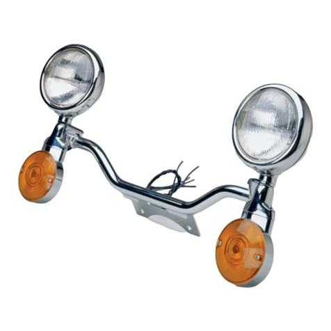
N944 LIGHT BAR for Honda® VTX1300 S
PARTS LIST
Screwdriver, #2 Phillips
Socket, 12mm, and Ratchet Wrench
Wrench, 12mm
Pliers, Slip Joint
Hex Key 5/32” or 4mm
Description Qty.
Lightbar Assembly, N944 1
Connectors, Scotchlok 6
10-24 Screw 4
M8 x 35 Screw 2
Washer , Flat 2
1. Make certain the motorcycle is securely positioned for this
installation. Cover the front fender with a protective cloth to avoid
scratches.
2. Remove Headlight from Headlight Shell (screwdriver), set aside.
3. Disconnect Turn signal wires inside Headlight Shell.
4. Remove the nuts holding the headlight shell to the lower triple
clamp. Nuts will be reused. (12mm socket and ratchet)
5. Remove Turn signals from motorcycle, set aside they will not be
reused.
6. Use the 10-24 screws to mount the Turn Signals to the light bar.
PREPARATION
INSTALLATION
1. Mount the Light Bar Assembly:
A. Place the Light Bar assembly so the center mount bracket is
between the lower Triple Clamp and the mounting bracket for
the Headlight Shell.
B. From the top, insert the M8 x 35 screws provided through the
Light Bar center mount bracket and into the triple clamp.
From underneith, install a flat washer and secure with stock
nut. Tighten to manufacturers specified torque. Figure 1& 2.
2. Wire the Light Bar assembly:
A. Route Spotlight wires into Headlight Shell.
B. Attach wires as recommended in the following list. Do
one at a time and check for correct operation. You may
need to change wire connections to get the correct oper
ation. (Connectors and Pliers).
Light Bar Motorcycle
Turnsignal, Left Short Red = Orange
Turnsignal, Right Short Red = Blue
Running Light, Left Short Black = Orange/White
Running Light, Right Short Black = Blue/White
Passing Lamps Long Blue = White (lo beam)
Ground = Green
3. Reinstall the headlight and rim.
4. Verify proper operation of all lights before riding.
10-110744-000 11/02
NOTE: Check local regulations for proper passing lamp opera-
tion. Some states require passing lamps be lit only with hi-beam.
NOTE: right and left on the motorcycle are determined from the
rider’s position.
Page 1 of 2
Wire From Light Bar
Insert To Stop.
Through Wire
NOTE: The service manual may be helpful in the installation.
NOTE: Grounding is through the fork and frame.
NOTE: An assistant will make steps 1 (A through B) easier.
Note, Light Bar Wiring Helpful Hints:
The long Blue wire is the main power wire for the spotlights on
the light bar. Connect that to the main power source from the
headlight. Either the High Beam wire or the Low Beam wire.
The choice is your preference. Turn on bike and Check.
The two short RED wires are for the turn signals. One RED wire
for the Left side turn signal and one for the Right side turn signal.
Turn on bike and check.
The two short BLACK wires are for the running lights. One
BLACK wire for the Left side running light and one for the Right
side running light. Turn on bike and check.
The Light Bar attached to the front fork of the motorcycle serves
as the ground in most cases. A precautionary step to insure
proper grounding is to take one of the Green Ground wires from
the existing turn signals and ground that between the Light Bar
Mount and the Triple Tree Bracket.
Always start by doing one side at a time. Preferably the right
side or high side of the bike first.
NOTE: check vertical aim of the lamps. They should
aim approximately 5° downward. If adjustment is
required see “Adjustment” page 2 of this instruction
otherwise proceed with wiring step 2.
Figure 1. Attach
Turn Signal with
10-24 Screws.
Figure 2
Figure 3
1. HORIZONTAL AIM
A.To adjust the Spotlights or Turnsignals right or left gently
rotate the lamp into the correct position. In the event that the
lamps become loose, refer to the procedure for vertical adjust-
ment.
2. VERTICAL AIM
A. Disconnect wire connections inside the Headlight Shell.
B. Pull the wires out of the Light Bar tube.
C. Turn the Turn signal to provide access to the mounting
screws.
D. Unscrew the Turn signal mounting screws and remove the
Turnsignal (Hex Key).
E. Push the Spotlight wire up into the Spotlight Shell.
F. Loosen the nut on the Spotlight stud (Deep Socket).
G. Now, adjust the Spotlight. Reconnect the spotlight wire and
illuminate to verify its projection.
H. Push wire into the Spotlight Shell.
I. Firmly retighten the nut on the Spotlight stud.
J. Pull the wire out of the Spotlight Shell.
K. Reassemble in reverse order of disassembly.
L. Adjust the Spotlights and Turn signals horizontally by rotat-
ing into position.
M.Verify operation of the lights.
Page 2 of 2 10-110744-000 11/02
©2002 National Cycle, Inc. PO Box 158, Maywood, IL 60153-0158 USA
708-343-0400 / Fax: 708-343-0625 / www.nationalcycle.com / e mail: [email protected]
ADJUSTMENT
MAINTENANCE
The high quality chrome finish of your National Cycle light
bar can be maintained with any quality chrome cleaner and
/or polish.
REPLACEMENT PARTS and ACCESSORIES
Order parts through your local dealer or contact National Cycle.
Description Part No.
Light Head Assembly 90-910501-000
Lamp Assembly E13/DOT
Reflector, Lens and Bulb 90-901011-000
Turn Signal
Assembly 90-930920-000
Turn Signal Lens 90-930213-000
Turn Signal Bulb Only: Bulb 1157 Available at Most Auto Parts Stores.
Light Bar Accessories
Chrome Visor N9005
Alternate Thumb Switch N9001
After wiring the light bar check for clearance. Make sure
the wires can not get pinched when the fork is turned to a
full fork lock left and right.
Check all lights for proper operation.
Check the tightness of all fasterners that have been
involved in this installation.
Installing optional N9005 Light
Head Visor.
1. Loosen the rim of the light
head assembly. (Phillips Screw
Driver).
2. Slip taps of Visor under rim.
Item E.
3. Shape Visor / Visor Tabs to
conform to contours of light head
assembly.
4. Retighten rim.
E
NOTE: As a substitute for the deep socket you may use a slotted socket such
as Snap On Brand part number FRX181 used in the auto trade as an OXY
Sensor Socket. This eliminates the need to disconnect and move the wires.
To adjust vertical aim you will need these
additional tools: Hex Key, 5/32" or 4mm
Deep Socket and Socket, 9/16" (14mm) or a 9/16”
Slotted Socket.

Other National Cycle Automobile Accessories manuals

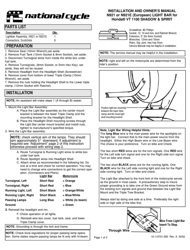
National Cycle N921 Installation instructions

National Cycle

National Cycle N921 Installation instructions

National Cycle Quantum Wash'n'Wipe N30205 Quick start guide

National Cycle

National Cycle Quantum Wash'n'Wipe N30205 Quick start guide

National Cycle Paladin P4013 Installation instructions

National Cycle

National Cycle Paladin P4013 Installation instructions

National Cycle Quantum hardcoated N30216 Quick start guide

National Cycle

National Cycle Quantum hardcoated N30216 Quick start guide

National Cycle P4014-003 User manual

National Cycle

National Cycle P4014-003 User manual

National Cycle Quantum Wash'n'Wipe N30208 Quick start guide

National Cycle

National Cycle Quantum Wash'n'Wipe N30208 Quick start guide

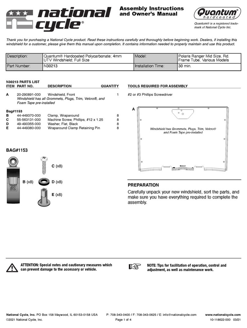
National Cycle Quantum N30213 Quick start guide

National Cycle

National Cycle Quantum N30213 Quick start guide

National Cycle N922 Installation instructions

National Cycle

National Cycle N922 Installation instructions

National Cycle N920 Installation instructions

National Cycle

National Cycle N920 Installation instructions

Popular Automobile Accessories manuals by other brands

Brodit 521667 manual

Brodit

Brodit 521667 manual

Yakima Whispbar K720W Fitting instructions

Yakima

Yakima Whispbar K720W Fitting instructions

Whispbar K193W Fitting instructions

Whispbar

Whispbar K193W Fitting instructions

Dometic S7 installation instructions

Dometic

Dometic S7 installation instructions

Axxess AXAC-CH5 installation instructions

Axxess

Axxess AXAC-CH5 installation instructions

Federal Signal Corporation CUDA TRIOPTIC 351011 Series instruction sheet

Federal Signal Corporation

Federal Signal Corporation CUDA TRIOPTIC 351011 Series instruction sheet

Nolan n-com bluetooth kit 2.1 Safety and instructions for use

Nolan

Nolan n-com bluetooth kit 2.1 Safety and instructions for use

Dynojet POWER VISION 3 installation guide

Dynojet

Dynojet POWER VISION 3 installation guide

Cruz 921-3 Series Assembly instructions

Cruz

Cruz 921-3 Series Assembly instructions

RBO IT FITS RBO1018 product manual

RBO

RBO IT FITS RBO1018 product manual

Monster iCruze IC-VOL1 Installation & user guide

Monster

Monster iCruze IC-VOL1 Installation & user guide

Tuff Tonneaus Bunji Ute installation instructions

Tuff Tonneaus

Tuff Tonneaus Bunji Ute installation instructions

RICA engineering iSoftloader manual

RICA engineering

RICA engineering iSoftloader manual

Prorack PR3213 manual

Prorack

Prorack PR3213 manual

Cruz Evo Rack Module E37 Assembly instructions

Cruz

Cruz Evo Rack Module E37 Assembly instructions

Omix-Ada Alloy RUGGED RIDGE 13782.35 instructions

Omix-Ada

Omix-Ada Alloy RUGGED RIDGE 13782.35 instructions

Bracketron MVM-35-05 installation manual

Bracketron

Bracketron MVM-35-05 installation manual

Seecode SEEFreeKit user manual

Seecode

Seecode SEEFreeKit user manual

manuals.online logo
manuals.online logoBrands
  • About & Mission
  • Contact us
  • Privacy Policy
  • Terms and Conditions

Copyright 2025 Manuals.Online. All Rights Reserved.