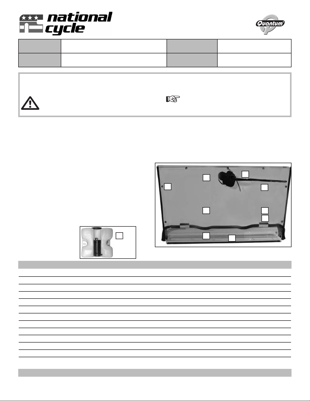
Assembly Instructions
and Owner’s Manual
Description: uantum® Hardcoated Polycarbonate
UTV Windshield, Wash’n’Wipe™ Full Size
Model: Polaris Ranger Mid Size, Rd.
Frame Tube, Various Models
Part Number: N30205 Installation Time: 60 min.
Thank you for purchasing a National Cycle product. Read these instructions carefully and thoroughly before beginning work.
Dealers, if installing this windshield for a customer, please give them this manual. It contains information needed to properly
maintain and use this product.
Attention:
Special notes and cautionary measures which can pre-
vent damage to the accessory or vehicle.
Note:
Tips for facilitation of installation, operation, and
adjustment, as well as maintenance work.
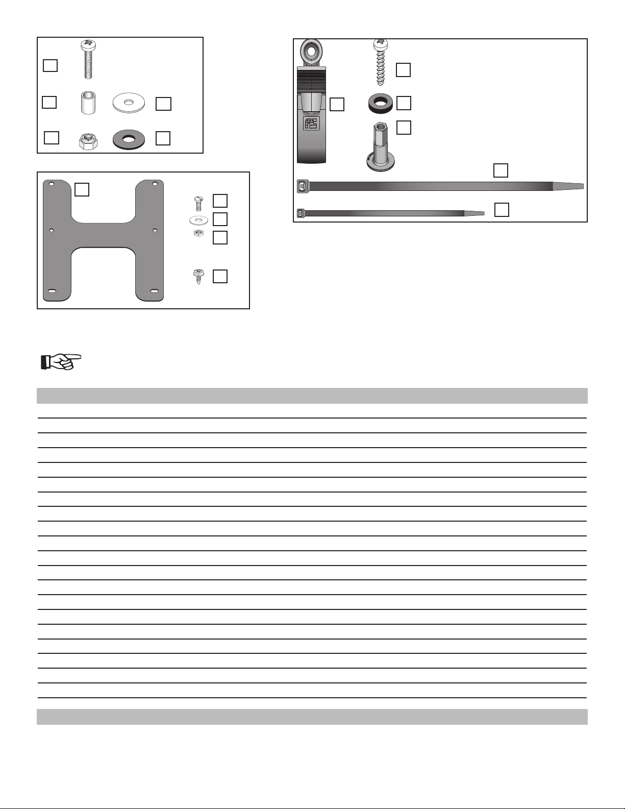
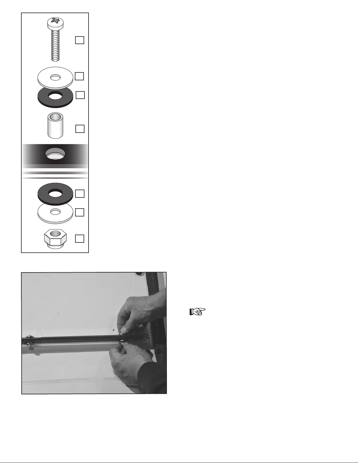
Item Part No. Description Qty. Notes and Tools
1 20-290399-000 Windscreen, Upper Section 1 Grommets Installed
2 20-290431-000 Windscreen, Lower Section 1 Grommets and Velcro Fastener Installed
3 44-447165-000 Grommets for Windshield 9 Installed on Windscreen
4 77-771157-000 Marine Grade Velcro, Hook 2 Installed on Windscreen
5 77-771158-000 Marine Grade Velcro, Loop 2 Installed on Windscreen
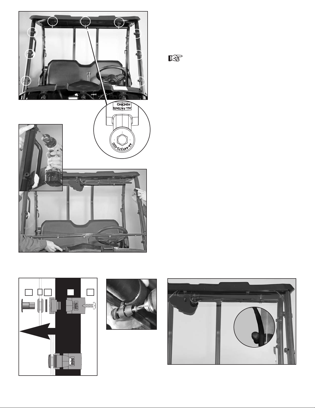
6 80-875150-000 Motor Assembly 1 Installed on Windscreen
7 80-875153-000 Arm, Wiper Assembly, 14” 350mm 1 Replacement Arm art No. is N30910
8 80-875154-000 Blade, Wiper Assembly, 14” (350mm) 1 Replacement Blade art No. is N30900
9 44-447003-000 Foam Tape, 1/8 x 1” W 1 Installed on Windscreen
ARTS IN KIT
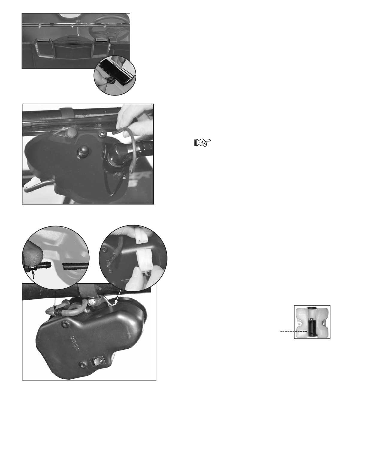
10 44-442523-000 Reservoir & Pump Assembly 1
11 80-830326-000 Wire Harness and Switch 1 With Grommet and Switch, age 3
arts Installed on Two- art Windscreen Tools Required
National Cycle, Inc.
PO Box 158, Maywood, IL 60153-0158 P. 708-343-4000 / F. 708-343-0625 / E. [email protected] www.nationalcycle.com©2015 National Cycle, Inc. Page 1 of 12 10-118032-000 05/15
RE ARATION
This it has been carefully packed and inspected at the factory. Report any missing part directly to National Cycle, Inc.
along with the Bag No. and Date on outside of Windshield Carton.
Carefully unpack the windshield, sort the parts, and make sure you have everything required to complete the installation
to the vehicle.
TOOL LIST
T27 Torx
3/8 and 7/16” Box Wrench
Flat Blade Screwdriver
Scribe or Marker
X-Acto® nife, or similar
Wire Cutters
Power Drill with 3/4” (19mm) hole saw, or similar
Small Drill Bit (1/8”) (3mm) for pilot hole
#2 or #3 Phillips Screw Driver or Phillips Bit for Drill
1/4” Hex Driver
arts List Continues on Next age
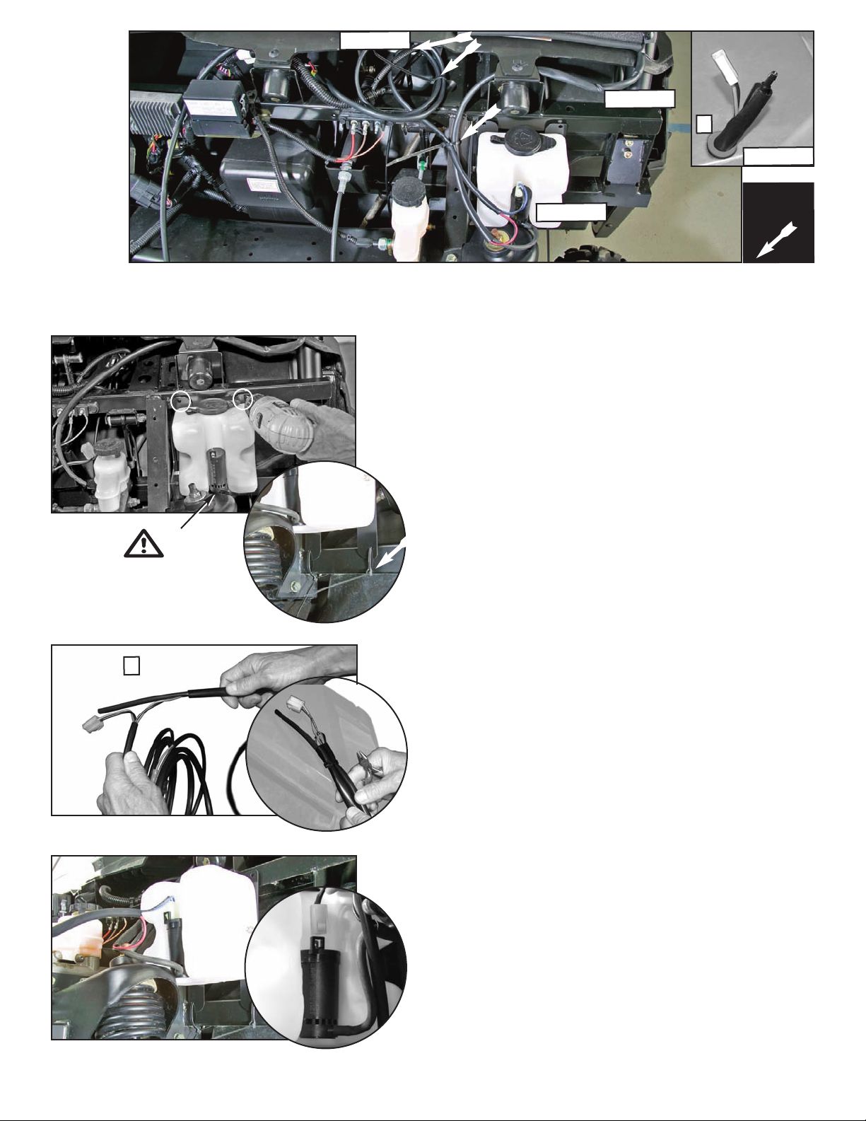
RESERVOIR and
WIRE HARNESS
(Harness, Page 3)
3
x9
1
x1
6
x1
7
x1
8
x1
2
x1
9
x1
4
x2
5
x2
10
x1