National Instruments NI SMD-7613 User manual

GETTING STARTED
NI SMD-7613/7614/7615/7616
Stepper Motor Drives
Note If you are a new user of LabVIEW or are unfamiliar with LabVIEW, refer to
the Getting Started with LabVIEW manual for information about LabVIEW and
LabVIEW terminology.
This document explains how to install and configure the NI SMD-7613/7914/7615/7616 stepper
motor drive.
Contents
What You Need to Get Started ................................................................................................. 1
Hardware .......................................................................................................................... 1
Software............................................................................................................................ 2
Related Documentation .................................................................................................... 2
Hardware Installation and Configuration ................................................................................. 3
Step 1: Connect the Drive to the NI PS-12/13 Power Supply .......................................... 3
Step 2: Connect the SMD to the Motor ............................................................................ 4
Step 3: Connect the Drive to the Network........................................................................ 7
Step 4: Verify the Connections......................................................................................... 11
Using the SMD with SoftMotion.............................................................................................. 11
Running the Example ....................................................................................................... 11
Understanding the Example.............................................................................................. 12
Worldwide Support and Services ............................................................................................. 13
What You Need to Get Started
You need the following items to get started.
Hardware
12 VDC to 80 VDC power supply. NI PS-12 (NI part number 748906-01) or NI PS-13
(NI part number 748907-01) recommended.
Tool for inserting wires into a screw terminal connector
A PC running Microsoft Windows 8.1/8/7/Vista/XP SP3, with an available Ethernet port

2|ni.com |Getting Started NI SMD-7613/7614/7615/7616 Stepper Drives
A CAT5 Ethernet cable (not included)
NI SMD-7613/7914/7615/7616 device
Software
LabVIEW 2014 or later
LabVIEW SoftMotion Module 2014 f1 or later
NI Stepper Configuration Utility, available from ni.com/downloads
Note The following instructions assume all required software is installed. For help
installing the required software, refer to the documentation included with that
software.
Related Documentation
The following documents contain additional information that you may find helpful. All
referenced documents ship with the product and are available at ni.com/manuals.
• NI SMD-7613/7614/7615/7616 User Manual
•LabVIEW SoftMotion Module Help—Use this help file to learn about using the
NI SoftMotion Module in LabVIEW. To access this help file from LabVIEW, select
Help»LabVIEW Help, then expand the LabVIEW NI SoftMotion Module book on the
Contents tab.
•LabVIEW Help—Use the LabVIEW Help to access information about LabVIEW
programming concepts, step-by-step instructions for using LabVIEW, and reference
information about LabVIEW VIs, functions, palettes, menus, tools, properties, methods,
events, dialog boxes, and so on. The LabVIEW Help also lists the LabVIEW documentation
resources available from National Instruments. Access the LabVIEW Help by selecting
Help»LabVIEW Help.
•Getting Started with LabVIEW—Use this document as a tutorial to familiarize yourself
with the LabVIEW graphical programming environment and the basic LabVIEW features
you use to build data acquisition and instrument control applications. Access the Getting
Started with LabVIEW PDF by selecting Start»All Programs»National Instruments»
LabVIEW»LabVIEW Manuals»LV_Getting_Started.pdf.

Getting Started NI SMD-7613/7614/7615/7616 Stepper Drives |© National Instruments |3
Hardware Installation and Configuration
This section covers the hardware setup for the NI SMD-7613/7914/7615/7616 device.
Step 1: Connect the Drive to the NI PS-12/13 Power
Supply
Note Do not plug in or turn on the power supply until after you complete all of the
following steps.
Complete the following steps to connect the power supply to AC input power and to the drive.
Figure 1 shows the power supply terminals.
Figure 1. NI PS-12/13 Power Supply Terminals
1. Connect an AC input cable to the line, neutral, and ground (protective earth) connectors.
2. Connect one end of a 1.02 mm to 0.81 mm diameter (18 to 20 AWG) gauge stranded wire
to the V+ terminal on the power supply.
3. Connect the free end of the V+ wire to the corresponding terminal on the included power
connector. Tighten the screw to ensure a secure connection.
4. Connect one end of a 1.02 mm to 0.81 mm diameter (18 to 20 AWG) gauge stranded wire
to the V- terminal on the power supply.
5. Connect the free end of the V- wire to the corresponding terminal on the included power
connector. Tighten the screw to ensure a secure connection.
6. Insert the power connector into the stepper motor drive. Tighten the screws to ensure a
secure connection.
7. Connect the power supply to AC power. The green Drive Status LED on the SMD should
be solid or flashing. For information about blink code meanings, refer to the user manual
for your device.
1 +24 V (NI PS-12) or +48 V (NI PS-13) Output
2 +24 V (NI PS-12) or +48 V (NI PS-13) Ground
3 AC Input Ground (Protective Earth)
4 AC Input Neutral
5 AC Input Line
LN-V+V
Made in China
+V ADJ
+
OUTPUT: 48V 6.7A INPUT: 100-240VAC 5A 50/60Hz
LN-V+V
Made in China
+V ADJ
+
Serial No.
1234 5

4|ni.com |Getting Started NI SMD-7613/7614/7615/7616 Stepper Drives
Step 2: Connect the SMD to the Motor
The drive supports various stepper motors. The connection to the stepper motor depends on the
number of leads present. Refer to the following figures to connect your stepper motor.
Note Motor wire colors are correct for NI stepper motors compatible with the
NI SMD-761x. These wire colors may not match a third-party stepper motor.
Four Lead Motors
Four lead motors can only be configured according to the following diagram.
Figure 2. Four Lead Motor Connection
Phase A+
Phase A–
Phase B+
Phase B–
Red
Blue
Yellow
White

Getting Started NI SMD-7613/7614/7615/7616 Stepper Drives |© National Instruments |5
Six Lead Motors
Six lead motors can be connected in series or center tap.
Figure 3. Six Lead Motor Connected in Series
Figure 4. Six Lead Motor Connected in Center Tap
Phase A+Green
White No Connect
No Connect
Phase A–Grn/Wht
Phase B+Red/Wht
Red
Black
Phase B–
No ConnectGreen
White Phase A+
Phase B+
Phase A–Grn/Wht
No ConnectRed/Wht
Red
Black
Phase B–

6|ni.com |Getting Started NI SMD-7613/7614/7615/7616 Stepper Drives
Eight Lead Motors
Eight lead motors can be connected in series or parallel.
Figure 5. Eight Lead Motor Connected in Series
Figure 6. Eight Lead Motor Connected in Parallel
Phase B–
Phase A+
Phase A–
Phase B+
Orange
Org/Wht
Blk/Wht
Black
Red
Red/Wht
Yel/Wht
Yellow
Phase B–
Phase A+
Phase A–
Phase B+
Orange
Red
Yel/Wht
Red/Wht
Yellow
Black
Org/Wht
Blk/Wht

Getting Started NI SMD-7613/7614/7615/7616 Stepper Drives |© National Instruments |7
Step 3: Connect the Drive to the Network
The drive requires only a CAT5 Ethernet cable connection. You can connect the drive directly
to your PC’s network card, to an auxiliary network card in your PC, or to a router or network
switch.
1. Physically connect the device to your network (or directly to the PC).
2. Set the drive IP address.
3. Set the appropriate networking properties on your PC.
Your device includes a 16 position rotary switch for setting its IP address. The factory default
address for each switch setting is shown in the table below.
The IP address corresponding to positions 1 through E can be changed using the NI Stepper
Configuration Utility software. Setting 0 is always 10.10.10.10, the universal recovery address.
Setting F is DHCP, which commands the device to get an IP address from a DHCP server on the
network. The IP address automatically assigned by the DHCP server may be dynamic or static
Table 1. IP Address Rotary Switch Settings
Position IP Address
010.10.10.10
1192.168.1.10
2192.168.1.20
3192.168.1.30
4192.168.0.40
5192.168.0.50
6192.168.0.60
7192.168.0.70
8192.168.0.80
9192.168.0.90
A192.168.0.100
B192.168.0.110
C192.168.0.120
D192.168.0.130
E192.168.0.140
FDHCP

8|ni.com |Getting Started NI SMD-7613/7614/7615/7616 Stepper Drives
depending on how the administrator has configured DHCP. The DHCP setting is reserved for
advanced users.
Your PC, or any other equipment that you use to communicate with the device, will also have a
unique address.
On the device switch settings 1 through E use the standard class B subnet mask
(i.e., 255.255.0.0). The mask for the universal recovery address is the standard class A
(i.e., 255.0.0.0).
Option 1: Connect a Drive to Your LAN
If you have a spare port on a switch or router and if you are able to set your device to an IP
address that is compatible with your network, and not used by anything else, this is a simple way
to get connected. This technique also allows you to connect multiple devices to your PC. If you
are on a corporate network, check with your system administrator before connecting anything
new to the network. He or she should be able assign you a suitable address and help you get
going.
Figure 7. Example Network Configuration
Many networks use dynamic addressing where a DHCP server assigns addresses on demand.
The address you choose for your device might get assigned to something else by the DHCP
server at another time.
Once you’ve chosen an appropriate IP address for your device, set the rotary switch according
to the address table above. If none of the default addresses are acceptable for your network, you
can enter a new table of IP addresses using the NI Stepper Configuration Utility. If your network
uses addresses starting with 192.168.0, the most common subnet, you will want to choose an
address from switch settings 4 through E. Another common subnet is 192.168.1. If your
network uses addresses in this range, the compatible default selections are 1, 2 and 3. If your PC
address is not in one of the above private subnets, you will have to change your subnet mask to
255.255.0.0 in order to communicate with your device. To change your subnet mask:
1. Open Network Connections.
a. (Windows 8.1/8/7/Vista) Open Control Panel. From the icon view, open Network
and Sharing Center, then click Change Adapter Settings.
b. (Windows XP) Right-click My Network Places and select Properties.
NIC PC
LAN Drive
Switch
or
Router

Getting Started NI SMD-7613/7614/7615/7616 Stepper Drives |© National Instruments |9
2. Right-click your network interface card (NIC) and select Properties.
a. (Windows 8.1/8/7/Vista) Scroll down and select (TCP/IPv4), then click Properties.
b. (Windows XP) Scroll down and select Internet Properties (TCP/IP), then click
Properties.
3. If the Obtain an IP address automatically option is selected, your PC is getting an IP
address and a subnet mask from the DHCP server. Cancel this dialog and proceed to the
Using DHCP section.
4. If the option Use the following IP address is selected, change the subnet mask to
255.255.0.0 and click OK.
Using DHCP
If you want to use your device on a network where all or most of the devices use dynamic IP
addresses supplied by a DHCP server, set the rotary switch to “F”. When the device is connected
to the network and powered on, it will obtain an IP address and a subnet mask from the server
that is compatible with your PC. However, you will not know what address the server assigns to
the device. The NI Stepper Configuration Utility can find your device using the Drive Discovery
feature, as long as your network isn’t too large. When the device connected to the network is
powered on, select Drive Discovery from the Drive menu to launch the Network Interface
Dialog dialog box.
Figure 8. Network Interface Dialog Box
Normally, Drive Discovery only detects one network interface card (NIC), and selects it
automatically. If you are using a laptop and have both wireless and wired network connections,
a second NIC may appear. Please select the NIC that you use to connect to the network to which
you’ve connected your device. Then click OK. Drive Discovery notifies you as soon as it has
detected a device.
If you think this is the correct device, click Yes. If you are not sure, click Not Sure and Drive
Discovery will look for additional devices on you network. Once you have told Drive Discovery
which device is yours, it automatically enters the device IP address in the IP address text box so
that you are ready to communicate.

10 |ni.com |Getting Started NI SMD-7613/7614/7615/7616 Stepper Drives
Option 2: Connect a device Directly to Your PC
1. Connect one end of a CAT5 Ethernet cable into the LAN card (NIC) on your PC and the
other into the device. You don’t need a special crossover cable; the device automatically
detects the direct connection and make the necessary physical layer changes.
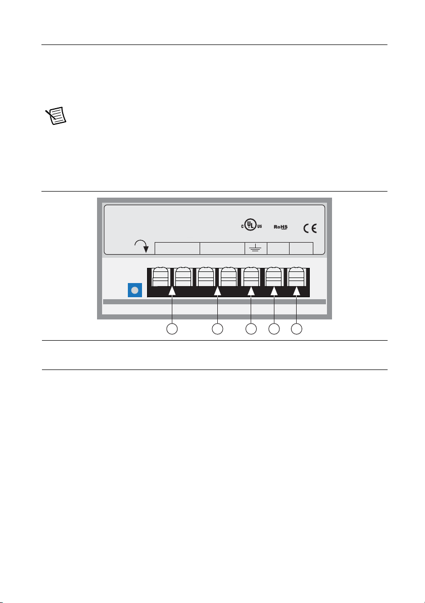
2. Set the IP address on the device to 10.10.10.10 by setting the rotary switch to position 0.
3. To set the IP address of your PC:
a. (Windows 8.1/8/7/Vista) Open Control Panel. From the icon view, open Network
and Sharing Center, then click Change Adapter Settings.
b. (Windows XP) Right-click My Network Places and select Properties.
4. Right-click your network interface card (NIC) and select Properties.
a. (Windows 8.1/8/7/Vista) Scroll down and select (TCP/IPv4), then click Properties.
b. (Windows XP) Scroll down and select Internet Properties (TCP/IP), then click
Properties.
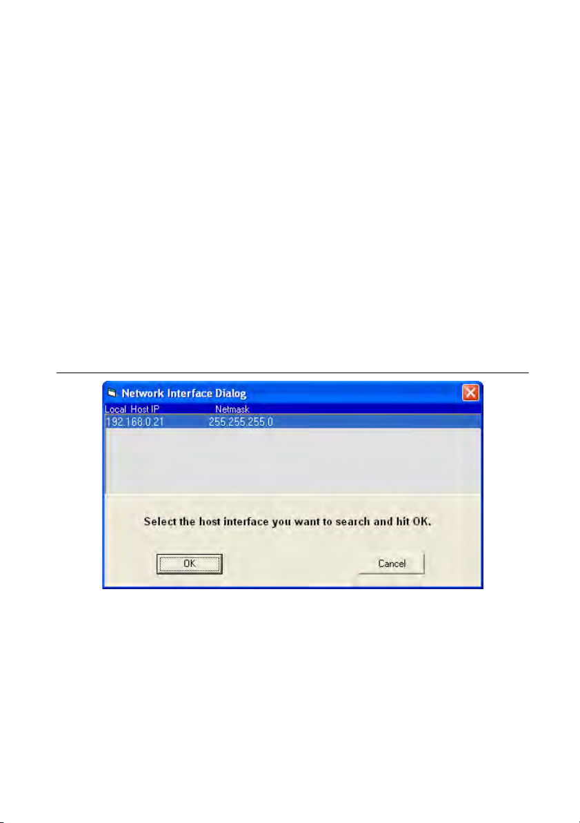
5. Select Use the following IP address and enter the address 10.10.10.11. This assigns
your PC an IP address that is on the same subnet as the device. Windows directs any traffic
intended for the device’s IP address to this interface card.
6. Next, enter the subnet mask as 255.255.255.0.
7. Leave Default gateway blank. This prevents your PC from looking for a router on this
subnet.
Note Because you are connected directly to the device, anytime the device is not
powered you will receive a small message bubble in the corner of your screen saying
“The network cable is unplugged.”
Option 3: Use Two Network Interface Cards (NICs)
This technique allows you to keep your PC connected to your LAN, but keeps the device off the
LAN, preventing possible IP conflicts or excessive traffic.
1. If you use a desktop PC and have a spare card slot, install a second NIC and connect it
directly to the device using a CAT5 cable. You don’t need a special “crossover cable”; the
device will automatically detect the direct connection and make the necessary physical
layer changes.
2. If you use a laptop and only connect to your LAN using wireless networking, you can use
the built-in RJ45 Ethernet connection as your second NIC.
3. Set the IP address on the device to 10.10.10.10 by setting the rotary switch to position 0.
4. To set the IP address of your PC:
a. (Windows 8.1/8/7/Vista) Open Control Panel. From the icon view, open Network
and Sharing Center, then click Change Adapter Settings.
b. (Windows XP) Right-click My Network Places and select Properties.

Getting Started NI SMD-7613/7614/7615/7616 Stepper Drives |© National Instruments |11
5. Right-click your network interface card (NIC) and select Properties.
a. (Windows 8.1/8/7/Vista) Scroll down and select (TCP/IPv4), then click Properties.
b. (Windows XP) Scroll down and select Internet Properties (TCP/IP), then click
Properties.
6. Select Use the following IP address and enter the address 10.10.10.11. This assigns
your PC an IP address that is on the same subnet as the device. Windows directs any traffic
intended for the device’s IP address to this interface card.
7. Next, enter the subnet mask as 255.255.255.0.
8. Leave Default gateway blank. This prevents your PC from looking for a router on this subnet.
Note Because you are connected directly to the device, anytime the device is not
powered you will receive a small message bubble in the corner of your screen saying
“The network cable is unplugged.”
Step 4: Verify the Connections
Once the drive is powered and connected to the network, and the Status LED does not indicate
any errors, you can verify the connection by completing the following steps:
1. Launch NI Stepper Configuration Utility.
2. Locate the drive.
3. Open the Drive menu and select Self Test.
4. Click Start. The motor should begin to move. Click Stop to finish the test.
If the motor failed to move, verify the power and network connections. Examine the Status LED
and refer to the drive user manual to diagnose any issues.
Using the SMD with SoftMotion
The drive can be used in a LabVIEW VI as a standard motion resource. To easily see the best
way to use the SMD in a VI, refer to the Axis Straight Line Move- Ethernet Stepper example.
To load the example VI included with SoftMotion 2014, navigate to <labview>\examples\
motion\Property Nodes\Axis Straight Line Move and launch Axis Straight Line
Move - Ethernet Stepper.
Running the Example
The example allows you to perform an Axis Straight Line Move using the SMD. To begin, open
the example front panel and configure the applicable parameters in the Move Constraints
control. The default values should be acceptable for the purposes of the example.
•Move Mode— Select the type of Axis Straight-Line Move to perform. Options are
Absolute, Relative, and Velocity. For information about the different kinds of moves, refer
to the SoftMotion Help.
•Axis— Enter the IP address of the drive. For example, a device using the universal recovery
address would be entered as niss:\\10.10.10.10.

12 |ni.com |Getting Started NI SMD-7613/7614/7615/7616 Stepper Drives
•Position— Specify the target position, in the axis will be driven toward.
•Velocity— Specific the maximum velocity of the move in steps/s.
•Acceleration— Specify the maximum rate of acceleration when starting the move, in
Units/s2.
•Deceleration— Specify the maximum rate of deceleration when stopping the move, in
Units/s2.
When all the settings are configured, run the VI, and click the Start Move button. The motor
should turn according to the configured move. Click the Stop Move button to stop the motor,
and the Stop VI when you are finished with the project.
Understanding the Example
The example VI begins by creating a motion resource and using an invoke node to enable the
drive.
Figure 9. Creating a Motion Resource
When the move is started, all of the configured parameters are written with a property node. The
position feedback is read with an invoke node and displayed.
Figure 10. Applying the Move Parameters

© 2014 National Instruments. All rights reserved.
374811A-01 Sep14
Refer to the NI Trademarks and Logo Guidelines at ni.com/trademarks for more information on National Instruments trademarks. Other
product and company names mentioned herein are trademarks or trade names of their respective companies. For patents covering National
Instruments products/technology, refer to the appropriate location: Help»Patents in your software, the patents.txt file on your media, or the
National Instruments Patents Notice at ni.com/patents. You can find information about end-user license agreements (EULAs) and third-party
legal notices in the readme file for your NI product. Refer to the Export Compliance Information at ni.com/legal/export-compliance
for the National Instruments global trade compliance policy and how to obtain relevant HTS codes, ECCNs, and other import/export data. NI MAKES
NO EXPRESS OR IMPLIED WARRANTIES AS TO THE ACCURACY OF THE INFORMATION CONTAINED HEREIN AND SHALL NOT BE LIABLE FOR
ANY ERRORS. U.S. Government Customers: The data contained in this manual was developed at private expense and is subject to the applicable
limited rights and restricted data rights as set forth in FAR 52.227-14, DFAR 252.227-7014, and DFAR 252.227-7015.
After the move has been stopped, errors are cleared and the motion reference is destroyed.
Figure 11. Destroying Move Reference
Worldwide Support and Services
The National Instruments website is your complete resource for technical support. At ni.com/
support you have access to everything from troubleshooting and application development
self-help resources to email and phone assistance from NI Application Engineers.
Visit ni.com/services for NI Factory Installation Services, repairs, extended warranty, and
other services.
Visit ni.com/register to register your National Instruments product. Product registration
facilitates technical support and ensures that you receive important information updates from NI.
A Declaration of Conformity (DoC) is our claim of compliance with the Council of the European
Communities using the manufacturer’s declaration of conformity. This system affords the user
protection for electromagnetic compatibility (EMC) and product safety. You can obtain the DoC
for your product by visiting ni.com/certification. If your product supports calibration,
you can obtain the calibration certificate for your product at ni.com/calibration.
National Instruments corporate headquarters is located at 11500 North Mopac Expressway,
Austin, Texas, 78759-3504. National Instruments also has offices located around the world. For
telephone support in the United States, create your service request at ni.com/support or dial
1 866 ASK MYNI (275 6964). For telephone support outside the United States, visit the
Worldwide Offices section of ni.com/niglobal to access the branch office websites, which
provide up-to-date contact information, support phone numbers, email addresses, and current
events.
Other manuals for NI SMD-7613
2
This manual suits for next models
3
Table of contents
Other National Instruments DC Drive manuals

National Instruments
National Instruments NI 73 Series User manual

National Instruments
National Instruments SMD-7610 User manual

National Instruments
National Instruments ISM-7411 User manual

National Instruments
National Instruments NI 9512 User manual

National Instruments
National Instruments NI PXIe-4464 Manual

National Instruments
National Instruments NI MID-7604 User manual

National Instruments
National Instruments 9512 C Series User manual

National Instruments
National Instruments 9505E User manual

National Instruments
National Instruments NI MID-7654 User manual

National Instruments
National Instruments NI SMD-7613 User manual