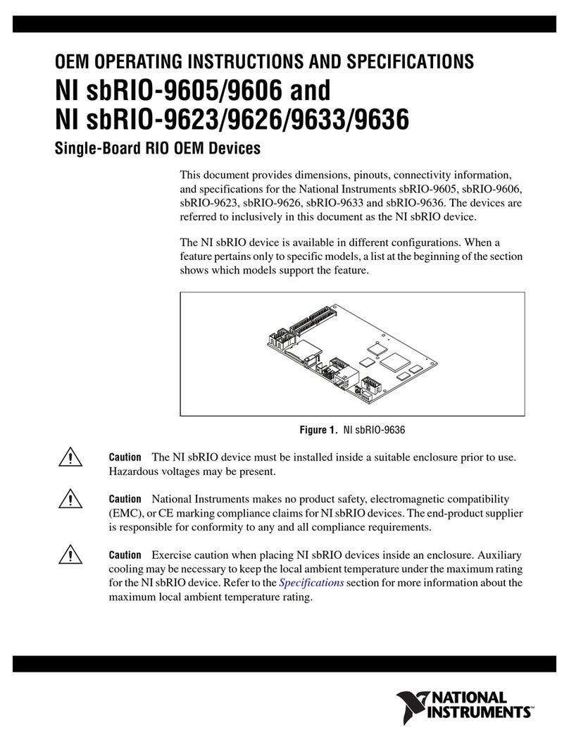
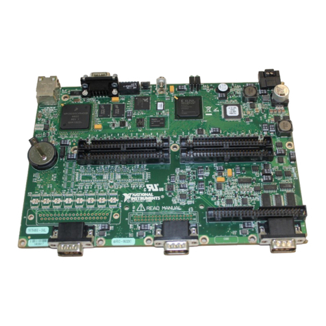
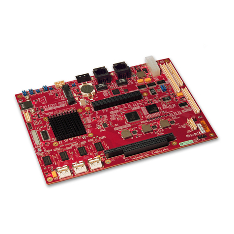
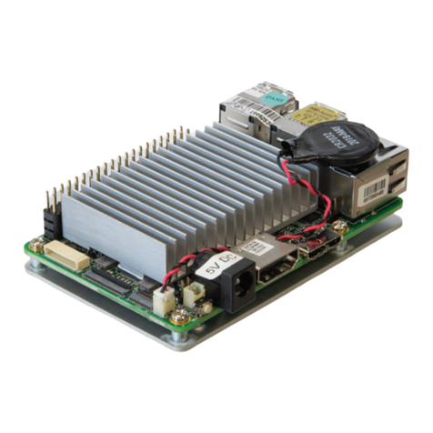
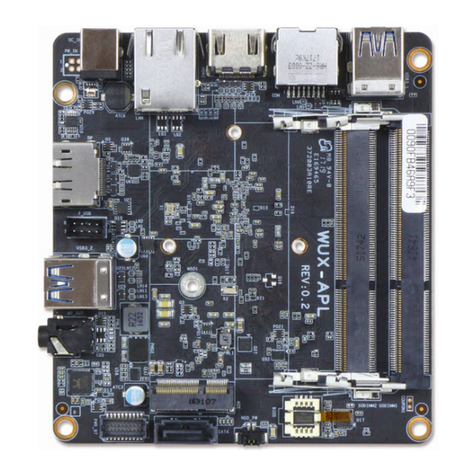
National Instruments sbRIO-9605 User manual

OEM OPERATING INSTRUCTIONS AND SPECIFICATIONS
NI sbRIO-9605/9606
Single-Board RIO OEM Devices
This document provides dimensions, pinouts, connectivity information,
and specifications for the National Instruments sbRIO-9605 and
sbRIO-9606. The devices are referred to inclusively in this document as the
NI sbRIO-960x.
Caution The NI sbRIO-960x must be installed inside a suitable enclosure prior to use.
Hazardous voltages may be present.
Caution National Instruments makes no product safety, electromagnetic compatibility
(EMC), or CE marking compliance claims for NI sbRIO devices. The end-product supplier
is responsible for conformity to any and all compliance requirements.
Caution Exercise caution when placing NI sbRIO devices inside an enclosure. Auxiliary
cooling may be necessary to keep the ambient temperate under the maximum rating for the
NI sbRIO device. Refer to the Specifications section for more information about the
maximum ambient temperature rating.
Caution Do not operate the NI sbRIO-960x in a manner not specified in these operating
instructions. Product misuse can result in a hazard. You can compromise the safety
protection built into the product if the product is damaged in any way. If the product is
damaged, return it to National Instruments for repair.
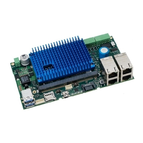
Figure 1. NI sbRIO-9606

NI sbRIO-960x OEM Instructions and Specifications 2 ni.com
What You Need to Get Started
This section lists the software and hardware you need to start programming
the NI sbRIO device.
Software Requirements
You need a development computer with the following software installed
on it. Go to ni.com/info and enter the Info Code rdsoftwareversion
for information about software version compatibility.
❑LabVIEW 2011 or later
❑LabVIEW Real-Time Module 2011 or later
❑LabVIEW FPGA Module 2011 or later
❑NI-RIO 4.0 or later
Hardware Requirements
You need the following hardware to use the NI sbRIO device.
❑NI sbRIO-960x
❑9–30 VDC power supply
❑Ethernet cable
❑Power Plug Assembly

©National Instruments Corporation 3 NI sbRIO-960x OEM Instructions and Specifications
I/O and Other Components on the NI sbRIO Device
Figure 2 shows the locations of I/O and other components on the NI sbRIO
device.
Figure 2. NI sbRIO-960x Component Location Diagram
1 Power Connector
2 Chassis Ground Bracket
3 USB Host Port (sbRIO-9606 only)
4 CAN IDC Header (CAN0) (sbRIO-9606 only)
5 RJ-45 Ethernet Port
6 RS-232 Serial IDC Header (COM1)
7ResetSwitch
8LEDs
9 RIO Mezzanine Card Connector
10 FPGA
11 NAND Flash
12 Processor
13 Mounting Holes Connected to Chassis Ground
14 CPLD
Primary Side Secondary Side
10
11
12
1313
8
14
9
125
346
7

NI sbRIO-960x OEM Instructions and Specifications 4 ni.com
Table 1 lists and describes the connectors on the NI sbRIO-960x and the
part number and manufacturer of each connector. Refer to the manufacturer
for information about using and matching these connectors.
Table 1. NI sbRIO Connector Descriptions
Connector Description
Manufacturer
and Part
Number
Recommended
Mating
Connector
NI
Solution
Power 2-position, mini-fit JR
w/ snap-in peg locks,
H = 0.411 in.
Molex,
46999-0144
Molex,
50-36-1673 w/
0457501211
NI,
152834-01
RS-232/CAN
IDC header
10-pin, 0.100 in. CT,
shrouded,
H = 0.370 in.
3M,
N2510-6002RB
or equivalent
Tyco,
1658622-1
NI,
153158-10
RMC
Connector
240-pin, 40 x 6 pos.,
high hensity open pin
field SEARAY
Samtec,
SEAF-40-06.5-
S-06-2-A-K-TR
Samtec,
SEAM-40-03.0-
S-06-2-A-K-TR
—

©National Instruments Corporation 5 NI sbRIO-960x OEM Instructions and Specifications
Dimensions
This section contains dimensional drawings of the NI sbRIO devices. For
three-dimensional models, refer to the Resources tab of the NI sbRIO
product page at ni.com.
Figure 3 shows the dimensions of the primary side of the NI sbRIO-960x.
Figure 3. NI sbRIO-960x Primary Side Dimensions in Millimeters (Inches)
1 Back of Front Panel
0 [.000]
0.64 (.025)
0 (.000)
FPGA
NAND Flash
Processor
20.63(.812)
Pin 1
17.17 (.676)
18.13(.714)
Pin 2
49.97(1.967)
69.96 (2.754)
74.24 (2.923)
30.81 (1.213)
52.91 (2.083)
61.82 (2.434)
69.47 (2.735)
Pin 1
Pin 2
1

NI sbRIO-960x OEM Instructions and Specifications 6 ni.com
Figure 4 shows the dimensions of the secondary side of the
NI sbRIO-960x.
Figure 4. NI sbRIO-960x Secondary Side Dimensions in Millimeters (Inches)
1 Holes and Keepouts Sized for M3 Standoff (4.5 mm Hex) or 4-40 Standoff (3/16” Hex)
3.800 [96.52]
71.72
(2.824)
102.87
(4.050)
73.63(2.899)
4x Ø 3.18(.125)
49.97 (1.967)
0 (.000)
0 (.000)
26.67 (1.050)
CPLD
3.2 (.126)
Pin 1
96.74 (3.809)
98.4 (3.874)
40.03(1.576)
52.91 (2.083)
76.84 (3.025)
1

©National Instruments Corporation 7 NI sbRIO-960x OEM Instructions and Specifications
Figure 5 shows the dimensions of the front of the NI sbRIO-960x.
Figure 5. NI sbRIO-960x Front Dimensions in Millimeters (Inches)
Note For more information about the dimensions of the NI sbRIO-960x, including
detailed dimensional drawings, go to ni.com/dimensions.
Maximum Component Heights
The primary side of the NI sbRIO-960x is the top side of the PCB where
the power connector and Ethernet connector are populated. The maximum
component height on the primary side of the PCB is split into two regions,
with the maximum component height of 17.27 mm (0.680 in.) on the front
edge and 4.06 mm (0.160 in.) on the remaining primary side. The
maximum component height on the secondary side of the PCB is 6.15 mm
(0.242 in.), excluding the RIO Mezzanine Card (RMC) Connector.
NI recommends that adjacent PCBs and surfaces observe a minimum
keepaway distance of 19.05 mm (0.75 in.) from the primary-side surface
and 7.62 mm (0.360 in.) from the secondary-side surface. For more
information refer to Figure 6, Figure 7, and Figure 8.
1 Minimum Clearance for Latch on Mating Power Connector
2 Maximum Height of RIO Mezzanine Card Components
3 4-40 threads, Maximum Torque of 3.6 in.-lbs
0 (.000)
Ø 3(.118)
18.16 (.715)
16 (.630)
6.16 (.242)
0 (.000)
2.16 (.085)
5.34 (.210)
2.54 (.100)
5.08(.200)
7.62 (.300)
10.16 (.400)
33.8(1.331)
49.93(1.966)
57.51 (2.264)
70.01 (2.756)
89.81 (3.536)
95.21 (3.748)
8.76 (.345)
3.66 (.144)
6.32 (.249)
6.15 (.242)
19.48(.767)
76.84 (3.025)
4x Ø 2.8(.071)
1
2
3

NI sbRIO-960x OEM Instructions and Specifications 8 ni.com
Figure 6. NI sbRIO-960x Maximum Component Height of
Primary Surface in Millimeters (Inches)
Figure 7. NI sbRIO-960x Max Component Height of
Secondary Surface in Millimeters (Inches)
Max Component Height = 4.06 (0.160)
Max Component Height = 17.21 (0.680)
31.75 (1.250)
Max Component Height = 6.15 (0.242)
Max Component Height = 7.62 (0.300)
60.96 (2.400)
.450 (11.43)
10.16 (.400)

©National Instruments Corporation 9 NI sbRIO-960x OEM Instructions and Specifications
Mounting the NI sbRIO-960x
The following sections describe how to mount and mate RIO Mezzanine
Cards to the NI sbRIO-960x.
Mounting the NI sbRIO-960x to Surface
Figure 8. NI sbRIO-960x Mounting Procedure
Note Mounting holes on the NI sbRIO-960x are designed to accommodate M3 or 4-40
fasteners, and standoffs or bosses up to 4.5 mm or 3/16 in. in diameter.
1 0.300 in. Keepaway Distance 2 Mounting Surface
2
1

NI sbRIO-960x OEM Instructions and Specifications 10 ni.com
Mating the NI sbRIO-960x to a RIO Mezzanine Card
Figure 9. NI sbRIO-960x Mating Procedure
Note When using the recommended Samtec SEARAY male connector
(SEAM-40-03.0-5-06-2-A-K-TR), separate the boards with a 9.65 mm (0.380 in.)
standoff, such as NI 153166-01.
1 M3 or 4-40 Standoff or Fastener
2 RIO Mezzanine Card (RMC) Connector
3ExampleRMC
4 Mounting Surface
1
2
3
4

©National Instruments Corporation 11 NI sbRIO-960x OEM Instructions and Specifications
Connector Pinouts
The following figures show the pinouts of the I/O connectors on the
NI sbRIO devices.
Power Connector
Figure 10. Pinout of the Power Connector
RS-232 / CAN Connectors
Figure 11. Pinout of the 10-Pin RS-232 and CAN Connectors
V
C2
1
Pin 1
CAN0_L
NC
V– (GND)
NC
SHIELD
NC
SHIELD
CAN0_H
V– (GND)
NC
10 9
87
65
43
21
RXD
DTR
DSR
CTS
SHIELD
DCD
GND
RTS
TXD
RI
10 9
87
5
6
43
2
1
Pin 1
RS-232
CAN
Pin 1

NI sbRIO-960x OEM Instructions and Specifications 12 ni.com
RIO Mezzanine Card Connector
The RIO Mezzanine Card connector provides connections for 96 FPGA I/O
channels, as well as pins reserved for future use.
The table on the following page lists the pinout for the RIO Mezzanine
Card connector, indicating the pin number and corresponding function.
Note Users interested in additional processor functionality such as serial, CAN, USB, or
Ethernet should contact a local National Instruments representative for custom design
opportunities. A non-recurring engineering charge (NRE) may apply.
Note Reserved and unused lines should be left disconnected on RIO Mezzanine Cards.
Future versions of this manual may update their definition.
Note National Instruments suggests using pins DIO0 through DIO63 first to maintain
future compatibility. DIO64 through DIO95 are not guaranteed to be provided on future
products.
Caution RMCs are not hot-swappable. Disconnect power before mating.
Figure 12. RMC Connector Location and Dimensions on Example RIO Mezzanine Card
0 (.000)
1.65 (.065)
0 (.000)
36.83 (1.450)
Pin 1

©National Instruments Corporation 13 NI sbRIO-960x OEM Instructions and Specifications
Table 2. RIO Mezzanine Card Connector Pinout
1-RESERVED 2-RESERVED 3-RESERVED 4-RESERVED 5-RESERVED 6-RESERVED
7-RESERVED 8-RESERVED 9-RESERVED 10-RESERVED 11-RESERVED 12-RESERVED
13-RESERVED 14-RESERVED 15-RESERVED 16-RESERVED 17-GND 18-RESERVED
19-RESERVED 20-RESERVED 21-RESERVED 22-RESERVED 23-GND 24-RESERVED
25-RESERVED 26-RESERVED 27-RESERVED 28-RESERVED 29-USB_D+ 30-GND
31-RESERVED 32-RESERVED 33-RESERVED 34-RESERVED 35-USB_D– 36-GND
37-RESERVED 38-RST# 39-RESERVED 40-RESERVED 41-GND 42-RESERVED
43-RESERVED 44-RESERVED 45-RESERVED 46-RESERVED 47-GND 48-RESERVED
49-RESERVED 50-RESERVED 51-RESERVED 52-RESERVED 53-RESERVED 54-5V
55-RESERVED 56-RESERVED 57-RESERVED 58-RESERVED 59-RESERVED 60-5V
61-RESERVED 62-RESERVED 63-RESERVED 64-RESERVED 65-RESERVED 66-5V
67-RESERVED 68-RESERVED 69-RESERVED 70-RESERVED 71-RESERVED 72-5V
73-RESERVED 74-RESERVED 75-RESERVED 76-RESERVED 77-RESERVED 78-GND
79-RESERVED 80-RESERVED 81-RESERVED 82-RESERVED 83-GND 84-RESERVED
85-RESERVED 86-RESERVED 87-RESERVED 88-GND 89-DIO47 90-DIO15
91-RESERVED 92-DIO63 93-GND 94-DIO79 95-DIO46 96-GND
97-DIO95 98-GND 99-DIO31 100-DIO78 101-GND 102-DIO14
103-GND 104-DIO62 105-DIO30 106-GND 107-DIO45 108-DIO13
109-DIO94 110-DIO61 111-GND 112-DIO77 113-DIO44 114-GND
115-DIO93 116-GND 117-DIO29 118-DIO76 119-GND 120-DIO12
121-GND 122-DIO60 123-DIO28 124-GND 125-DIO43 126-DIO11
127-DIO92 128-DIO59 129-GND 130-DIO75 131-DIO42 132-GND
133-DIO91 134-GND 135-DIO27 136-DIO74 137-GND 138-DIO10
139-GND 140-DIO58 141-DIO26 142-GND 143-DIO41 144-DIO9
145-DIO90 146-DIO57 147-GND 148-DIO73 149-DIO40 150-GND
151-DIO89 152-GND 153-DIO25 154-DIO72 155-GND 156-DIO8
157-GND 158-DIO56 159-DIO24 160-GND 161-DIO39 162-DIO7
163-DIO88 164-DIO55 165-GND 166-DIO71 167-DIO38 168-GND
169-DIO87 170-GND 171-DIO23 172-DIO70 173-GND 174-DIO6
175-GND 176-DIO54 177-DIO22 178-GND 179-DIO37 180-DIO5
181-DIO86 182-DIO53 183-GND 184-DIO69 185-DIO36 186-GND
187-DIO85 188-GND 189-DIO21 190-DIO68 191-GND 192-DIO4
193-GND 194-DIO52 195-DIO20 196-GND 197-DIO35 198-DIO3
199-DIO84 200-DIO51 201-GND 202-DIO67 203-DIO34 204-GND
205-DIO83 206-GND 207-DIO19 208-DIO66 209-GND 210-DIO2
211-GND 212-DIO50 213-DIO18 214-GND 215-DIO33 216-DIO1
217-DIO82 218-DIO49 219-GND 220-DIO65 221-DIO32 222-GND
223-DIO81 224-GND 225-DIO17 226-DIO64 227-GND 228-DIO0
229-GND 230-DIO48 231-DIO16 232-GND 233-RESERVED 234-FPGA_VIO
235-DIO80 236-VBAT 237-GND 238-RESERVED 239-RESERVED 240-FPGA_VIO

NI sbRIO-960x OEM Instructions and Specifications 14 ni.com
RMC Power Requirements
The RIO Mezzanine Card connector provides power on six pins. The 5 V
rail consists of pins 54, 60, 66, and 72, and is the main source of power to
a RIO Mezzanine Card. The FPGA_VIO rail consists of pins 234 and 240,
and is used to supply I/O power and determine I/O levels for the FPGA I/O
pins.
Table 3 lists the rail requirements for each of the rails on a RIO Mezzanine
Card connector.
RIO Mezzanine Cards should not source any current onto any of the power
pins and should be able to tolerate 5 V and FPGA_VIO coming up in any
order.
3.3 V Digital I/O
The NI sbRIO-960x provides 3.3 V digital I/O via the RIO Mezzanine Card
connector. The following sections provide figures and specifications for a
single DIO channel on each connector.
3.3 V DIO on RMC Connector
Figure 13. Circuitry of One 3.3 V DIO Channel on the RIO Mezzanine Card Connector
The NI sbRIO 960x is tested with all DIO channels driving 3 mA DC loads.
DIO lines are floating before and during FPGA configuration. To ensure
startup values, place pull-up or pull-down resistors on a RIO Mezzanine
Card. The DIO channels on the NI sbRIO device are routed with a 55 Ω
characteristic trace impedance. Route all RIO Mezzanine Cards with a
similar impedance to ensure the best signal quality. Refer to 3.3 V DIO on
RMC Connector in the Specifications section for the logic levels.
Table 3. NI RIO Mezzanine Card Rail Requirements
Voltage Tolerance Max Current Max Ripple and Noise
5 V +/– 5% 1.5 A 50 mV
FPGA_VIO (3.3 V) +/– 5% 0.33 A 50 mV
Xilinx Spartan-6 FPGA RMC Connector
33 Ω

©National Instruments Corporation 15 NI sbRIO-960x OEM Instructions and Specifications
RMC VBAT
The NI sbRIO-960x implements an onboard real-time clock (RTC) to keep
track of absolute time. The RMC connector provides a VBAT line to power
the RTC. Without a battery, absolute time will be reset during a power
cycle. Batteries connected to VBAT must have a nominal output between
3.0 V and 3.6 V, and a maximum output of 3.7 V. If VBAT is not being
used, leave it disconnected.
USB on RMC Connector
The USB pair on the RMC Connector has a 90 Ωdifferential trace
impedance. To ensure the best possible signal integrity, route the USB pair
with a similar trace impedance. If USB is not being used, leave it
disconnected.
RMC RST#
The RST# signal indicates that power provided through the RMC
Connector is valid. RST# is guaranteed to be asserted for at least 1 ms.
There should be no more than 30 pF on the RST# line of a RIO Mezzanine
Card. This includes the RMC Connector, traces, vias, and device pins.
Refer to 3.3 V Digital I/O on RIO Mezzanine Card Connector in the
Specifications section for output logic levels.

NI sbRIO-960x OEM Instructions and Specifications 16 ni.com
Powering the NI sbRIO Device
The NI sbRIO-960x requires an external power supply that meets the
specifications in the Power Requirements section. The NI sbRIO-960x
filters and regulates the supplied power and provides power for RIO
Mezzanine Cards. The NI sbRIO-960x has one layer of reverse-voltage
protection. Complete the following steps to connect a power supply to the
chassis.
Caution Do not mate or unmate the power supply connectors while power is applied.
1. Ensure the power supply is off.
2. Connect the V lead of the power supply to position 1 of the power
connector, Figure 14 shows the positions on the power connector
.
Figure 14. NI sbRIO 960x Power Connector
3. Connect the C lead of the power supply to position 2 of the 2-position
power connector.
4. Insert the power connector into the front panel of the NI sbRIO-960x
until the connector latches into place.
5. Turn on the power supply.
Powering On the NI sbRIO Device
The NI sbRIO device runs a power-on self test (POST) when you apply
power to the device. During the POST, the Power and Status LEDs turn on.
When the Status LED turns off, the POST is complete. If the LEDs do not
behave in this way when the system powers on, refer to the Understanding
LED Indications section.
1 V Terminal 2CTerminal
1
2

©National Instruments Corporation 17 NI sbRIO-960x OEM Instructions and Specifications
Device Startup Options
You can configure the following device startup options in MAX:
• Safe Mode
• Console Out
•IPReset
• No App
• No FPGA App
To turn these startup options on or off, select the controller under Remote
Systems in the MAX configuration tree, then select the Controller
Settings tab. Refer to the MAX Help for information about the startup
options and how to configure the controller.
You can configure the device to launch an embedded stand-alone
LabVIEW RT application each time it resets. Refer to the Running a
Stand-Alone Real-Time Application (RT Module) topic of the LabVIEW
Help for more information.
Device Reset Options
You can configure the device to launch a LabVIEW FPGA application each
time it is reset. Table 4 lists the reset options available on the NI sbRIO 960x.
These options determine how the FPGA behaves when the device is reset in
various conditions. Use the RIO Device Setup utility to select reset options.
Access the RIO Device Setup utility by selecting
Start»All Programs»
National Instruments»NI-RIO»RIO Device Setup
.
Note If you want a VI to run when loaded to the FPGA, complete the following steps.
1. Right-click the FPGA Target item in the Project Explorer window in LabVIEW.
2. Select Properties.
3. In the General category of the FPGA Target Properties dialog box, place a check in
the Run when loaded to FPGA checkbox.
4. Compile the FPGA VI.
Table 4. NI sbRIO Reset Options
Reset Option Behavior
Do not autoload VI Does not load the FPGA bit stream from flash memory.
Autoload VI on device powerup Loads the FPGA bit stream from flash memory to the FPGA
when the device powers on.
Autoload VI on device reboot Loads the FPGA bit stream from flash to the FPGA when you
reboot the device either with or without cycling power.

NI sbRIO-960x OEM Instructions and Specifications 18 ni.com
Understanding Ground Connections
The front I/O connector shields, chassis ground bracket, and mounting
holes near the front I/O are connected together internally to form chassis
ground. Chassis ground is capacitively coupled to digital ground near the
power connector. For the best possible ESD protection, connec chassis
ground at the mounting holes or the chassis ground bracket to a low
inductive earth ground.
When connecting the NI sbRIO-960x to external devices, ensure that stray
ground currents are not using the device as a return path. Significant stray
currents traversing through the NI sbRIO-960x can result in device failure.
To verify correct grounding of the NI sbRIO 960x, make sure the current
flowing into the power connector equals the current flowing out of the
power connector. These currents should be measured with a current probe
after final assembly of the end system. Investigate and remove any current
differences.
Connecting the NI sbRIO Device to a Network
Connect the device to an Ethernet network using the RJ-45 Ethernet port on
the controller front panel. Use a standard Category 5 (CAT-5) or better
shielded, twisted-pair Ethernet cable to connect the chassis to an Ethernet
hub, or use an Ethernet crossover cable to connect the chassis directly to a
computer.
Caution To prevent data loss and to maintain the integrity of your Ethernet installation,
do not use a cable longer than 100 m.
The first time you power up the chassis, it attempts to initiate a DHCP
network connection. If the chassis is unable to initiate a DHCP connection,
it connects to the network with a link-local IP address with the form
169.254.x.x. After powerup, you must install software on the chassis and
configure the network settings in Measurement & Automation Explorer
(MAX).
Note Installing software may change the network behavior of the chassis. For information
about network behavior by installed software version, go to ni.com/info and enter the
Info Code ipconfigcrio.

©National Instruments Corporation 19 NI sbRIO-960x OEM Instructions and Specifications
Connecting Serial Devices
The NI sbRIO device has an RS-232 serial port to which you can connect
devices such as displays or input devices. Use the Serial VIs to read from
and write to the serial port from a LabVIEW RT application. For more
information about using the Serial VIs, refer to the Serial VIs and
Functions topic of the LabVIEW Help.
Connecting CAN Networks
The NI sbRIO-9606 has one IDC header that provides connections to a
CAN bus. The NI sbRIO-9606 has pins for CAN_H and CAN_L, which
can connect to the CAN bus signals. The CAN port uses an NXP
PCA82C251T high-speed CAN transceiver that is fully compatible with
the ISO 11898 standard and supports baud rates up to 1 Mbps.
The port has two common pins (GND) that serve as the reference ground
for CAN_H and CAN_L. You can connect the CAN bus reference ground
(sometimes referred to as CAN_V–) to one or both COM pins. The port
also has an optional shield pin (SHLD) that can connect to a shielded CAN
cable. Connecting SHLD may improve signal integrity and EMC
performance.
CAN Bus Topology and Termination
A CAN bus consists of two or more CAN nodes cabled together. The
CAN_H and CAN_L pins of each node are connected to the main CAN bus
cable through a short connection called a stub. The pair of signal wires,
CAN_H and CAN_L, constitutes a transmission line. If the transmission
line is not terminated, signal changes on the bus cause reflections that can
cause communication errors. The CAN bus is bidirectional, and both ends
of the cable must be terminated. This requirement does not mean that every
node on the bus should have a termination resistor; only the two nodes at
the far end of the cable should have termination resistors.
Other manuals for sbRIO-9605
2
This manual suits for next models
1
Table of contents
Other National Instruments Single Board Computer manuals

National Instruments
National Instruments NI sbRIO-9627 User manual

National Instruments
National Instruments NI sbRIO-9611 User manual

National Instruments
National Instruments NI sbRIO-961 Series User manual

National Instruments
National Instruments sbRIO-9605 User manual

National Instruments
National Instruments NI sbRIO-9627 User manual