© PHYTEC America L.L.C. 2023 6
1.1 List of Figures
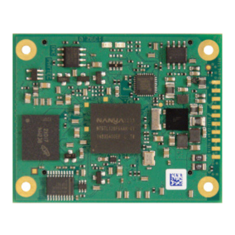
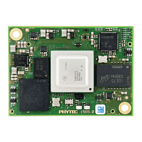
Figure 1. phyCORE-AM65x SOM............................................................................................................. 13
Figure 2. phyCORE-AM65x Block Diagram............................................................................................. 14
Figure 3. phyCORE-AM65x Dimensions Top View ................................................................................. 15
Figure 4. phyCORE-AM65x Dimensions Bottom View............................................................................ 16
Figure 5. phyCORE-AM65x Dimensions End View ................................................................................. 16
Figure 6. Top Down View of Mating Connectors..................................................................................... 17
Figure 7. Carrier Board Alignment Hole Placement................................................................................ 18
Figure 8. phyCORE-AM65x Component Placement (processor side) .................................................... 19
Figure 9. phyCORE-AM65x Component Placement (connector side)..................................................... 20
Figure 10. 3-Position Solder Jumper Pad Numbering Scheme ............................................................... 22
Figure 11. Jumper Locations (Processor side)........................................................................................ 25
Figure 12. Jumper Locations (Connector side) ....................................................................................... 26
Figure 13. Pinout of the phyCORE-Connector........................................................................................ 27
Figure 14. Pinout example using X_MMC1_DAT1 in our schematic....................................................... 28
Figure 15. Primary Power VIN(VCC_3V3) reference circuit ..................................................................... 40
Figure 16. SOM current reader reference circuit ..................................................................................... 41
Figure 17. Carrier board power reference circuit..................................................................................... 43
Figure 18. MMC1 SD-card Reader Reference Schematic......................................................................... 48
Figure 19. MMC1 Load Switch Reference Schematic.............................................................................. 48
Figure 20. BOOTMODE pullups/pulldowns.............................................................................................. 49
Figure 21. Reference Schematic for BOOTMODE configuration............................................................. 51
Figure 22. MCAN0 Reference Schematic................................................................................................. 52
Figure 23. RJ45 Reference Schematic..................................................................................................... 66
Figure 24. RGMII PHY Strapping Resistors Reference Schematic .......................................................... 67
Figure 25. RGMII PHY Reference Schematic ........................................................................................... 67
Figure 26. PCIe Connector Reference Schematic.................................................................................... 72
Figure 27. PCIe Clock Generator Reference Schematic .......................................................................... 72
Figure 28. USB 3.0 Connector Reference Schematic .............................................................................. 77
Figure 29. USB Micro Connector Reference Schematic.......................................................................... 78
Figure 30. USB Power Switch Reference Schematic............................................................................... 78
Figure 31. OLDI Connector Reference Schematic................................................................................... 81
Figure 32. CSI Power Toggle Reference Schematic ................................................................................ 83
Figure 33. CSI Connector Reference Schematic...................................................................................... 83
Figure 34. JTAG Reference Schematic.................................................................................................... 94
Figure 35. UART0 to USB Bridge Reference Schematic.......................................................................... 95
