Oxygen detectors –URS40SS
Gas detection systems for industrial environments
Oxygen excess
Since oxygen weighs more or less the same as air, unless there is forced or natural air
circulation, it tends to spread at the point of the leak.
So, the excess oxygen detectors must be installed near any likely leakage points, in order to
detect the excess oxygen as quickly as possible.
Oxygen deficiency
Detection of oxygen deficiency has the purpose of indirectly detecting the presence of other
gases that deplete the oxygen in the air, therefore causing asphyxiation problems, for example.
In this case, the detectors must be located at the breathing height of the occupants in the
premises. Take into consideration the following specific installation guidelines, as well as the
above instructions, for location of the detectors.
The detectors must be installed:
1. where accidental gas leakages are possible
2. at least 1.5m away from heat sources or from vent holes
3. not in spaces where ventilation is poor and where gas pockets may form
4. away from hindrances to natural gas flow
5. away from equipment that may leak gas during normal operations
6. in environments with a temperature range of -20°C to 50°C and relative humidity below
90% (non-condensing)
7. Disconnect equipment from the power supply when mounting and dismantling detectors.
Environmental
compatibility
and disposal
This product has been designed and constructed using materials and processes that take into
account the environmental issue. Refer to the following notes for disposal of the product at the
end of its working life, or when it is replaced:
-for disposal purposes, this product is classified as an electric and electronic device: do not
dispose of it with normal household waste, in particular as regards the printed circuit
-comply with all local laws in force
-as far as possible reuse basic materials to keep environmental impact to a minimum
-use local depots and waste recycling companies, or contact the supplier or manufacturer to
return used products or to ask for information on environmental compatibility and waste
disposal
-the product packaging can be reused. Keep it for future use or to return the product to the
supplier.
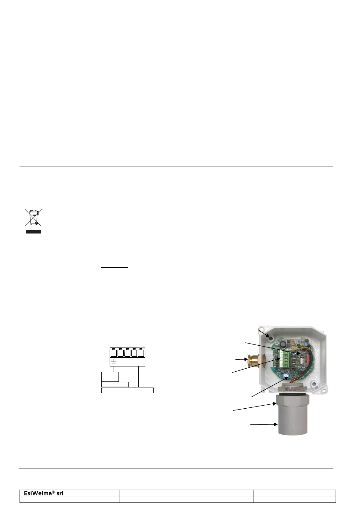
Electrical installation
and configuration
Terminal board and
electrical connections
Cabling:
CAUTION: Make the area safe and ensure that the device power supply is off
before cabling and configuration operations.
Install the sensor in compliance with EN60079-14.
The cable gland provided on the housing is used for cable entry. The diameter of the cable
sheath must be no more than 8 mm.
Ground the sensor using the internal grounding system.
Refer to the Control Unit manual for all cabling information (cable type and specifications, bus
topology, length of connections etc.) and configuration.
Depending on the connecting distance, use at least 4-core cable, min. diameter 0.75mm2up to
100m, 1mm2up to 200m, 1.5mm2up to 500m.
Use shielded cable where there is a risk of electromagnetic interference.
Power supply
and BUS
connector