Navman S100 User manual

RESET
SPEED
NAVMAN
NAVMAN


NAVMAN S100
ENGLISH .................................................................................... 3
FRANÇAIS – FRENCH ............................................................ 15
DEUTSCH – GERMAN............................................................. 27
NEDERLANDS – DUTCH ........................................................ 39
SVENSKA – SWEDISH............................................................ 51
ESPAÑOL – SPANISH.............................................................. 63
DEUTSCH – GERMAN............................................................. 27
ENGLISH .................................................................................... 3
ESPAÑOL – SPANISH.............................................................. 63
FRANÇAIS – FRENCH ............................................................ 15
NEDERLANDS – DUTCH ........................................................ 39
SVENSKA – SWEDISH............................................................ 51


3NAVMAN S100UserManual
Contents
Specifications . . . . . . . . . . . . . . . . . . . . . . . . . . . . . . . . . . . . . . . . . . . . . . . . . . . . . . . . 4
Installation . . . . . . . . . . . . . . . . . . . . . . . . . . . . . . . . . . . . . . . . . . . . . . . . . . . . . . . . . . . 5
Location . . . . . . . . . . . . . . . . . . . . . . . . . . . . . . . . . . . . . . . . . . . . . . . . . . . . . . . . . . 5
Mounting . . . . . . . . . . . . . . . . . . . . . . . . . . . . . . . . . . . . . . . . . . . . . . . . . . . . . . . . . . 5
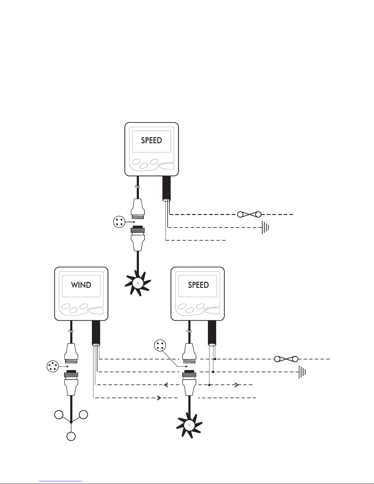
Wiring Connection . . . . . . . . . . . . . . . . . . . . . . . . . . . . . . . . . . . . . . . . . . . . . . . . . . 6
Multiple Instruments . . . . . . . . . . . . . . . . . . . . . . . . . . . . . . . . . . . . . . . . . . . . . . . . . 6
Operation . . . . . . . . . . . . . . . . . . . . . . . . . . . . . . . . . . . . . . . . . . . . . . . . . . . . . . . . . . . . 7
Function Select Keys . . . . . . . . . . . . . . . . . . . . . . . . . . . . . . . . . . . . . . . . . . . . . . . . 7
Backlighting On / Off . . . . . . . . . . . . . . . . . . . . . . . . . . . . . . . . . . . . . . . . . . . . . . . . . 7
Select Temperature Units . . . . . . . . . . . . . . . . . . . . . . . . . . . . . . . . . . . . . . . . . . . . . 7
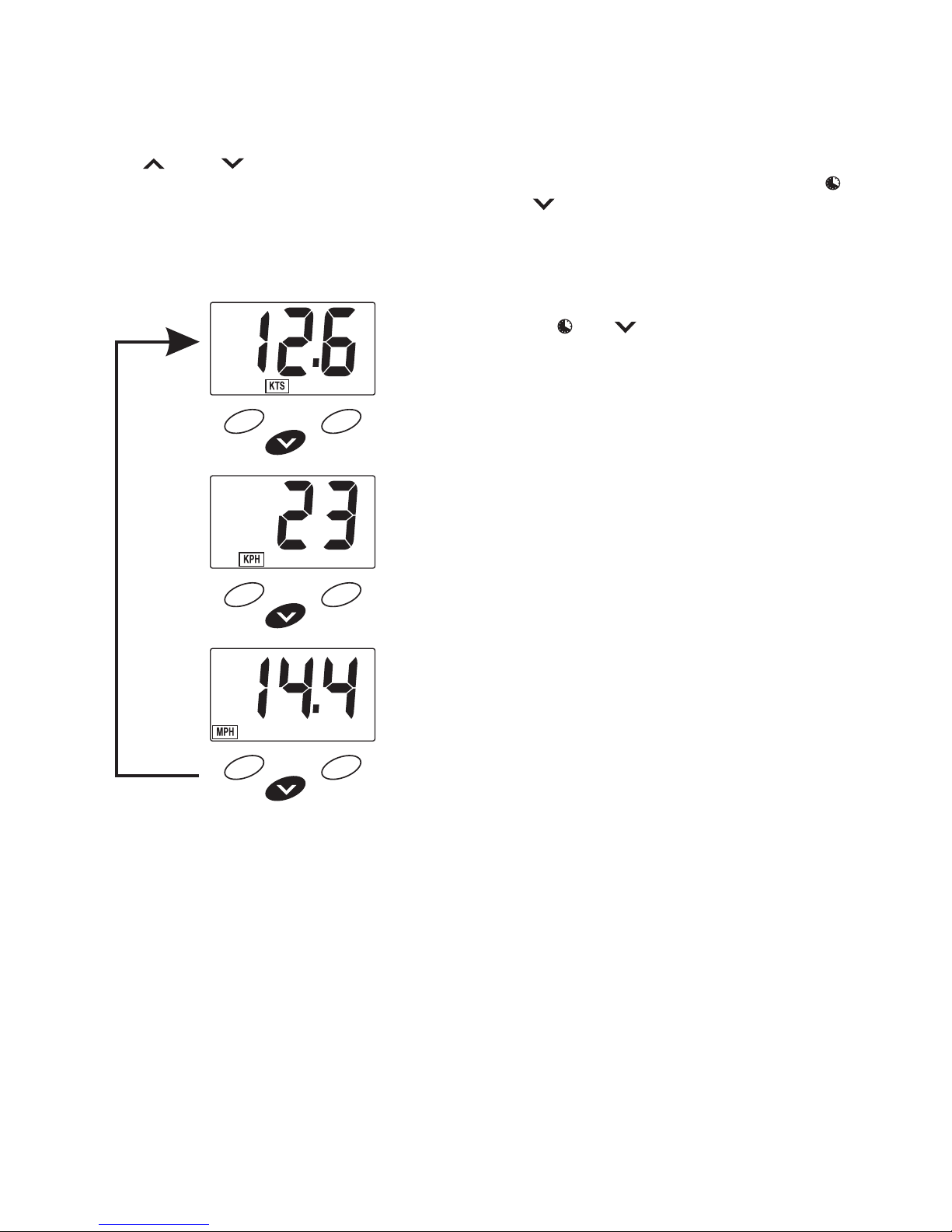
Select Speed Units . . . . . . . . . . . . . . . . . . . . . . . . . . . . . . . . . . . . . . . . . . . . . . . . . . 8
Reset Average Speed, Maximum Speed and Log. . . . . . . . . . . . . . . . . . . . . . . . . . 8
Reset Total Log . . . . . . . . . . . . . . . . . . . . . . . . . . . . . . . . . . . . . . . . . . . . . . . . . . . . . 8
Trend Indicator . . . . . . . . . . . . . . . . . . . . . . . . . . . . . . . . . . . . . . . . . . . . . . . . . . . . . 8
Elapsed Timer . . . . . . . . . . . . . . . . . . . . . . . . . . . . . . . . . . . . . . . . . . . . . . . . . . . . . . 9
Count Down Timers . . . . . . . . . . . . . . . . . . . . . . . . . . . . . . . . . . . . . . . . . . . . . . . . . 9
Secondary Functions . . . . . . . . . . . . . . . . . . . . . . . . . . . . . . . . . . . . . . . . . . . . . . . . . 10
Calibrate Temperature Display . . . . . . . . . . . . . . . . . . . . . . . . . . . . . . . . . . . . . . . . 11
Simulation Mode. . . . . . . . . . . . . . . . . . . . . . . . . . . . . . . . . . . . . . . . . . . . . . . . . . . 11
Speed Calibration . . . . . . . . . . . . . . . . . . . . . . . . . . . . . . . . . . . . . . . . . . . . . . . . . . . . 12
Speed Comparison Method . . . . . . . . . . . . . . . . . . . . . . . . . . . . . . . . . . . . . . . . . . 12
Log Calibration Method . . . . . . . . . . . . . . . . . . . . . . . . . . . . . . . . . . . . . . . . . . . . . 12
Troubleshooting Chart . . . . . . . . . . . . . . . . . . . . . . . . . . . . . . . . . . . . . . . . . . . . . . . . 13
S100/ENG/1C

4NAVMAN S100UserManual
Specifications
• Power supply
10.7 to 16.6 VDC 10 mA nominal, 30 mA
with backlight on.
• Operating temperature
0°C to 45°C.
• Size of display
112 x 112 x 24mm (4.4 x 4.4 x 1”) , overall
depth 35mm (1.4”) behind panel.
• Display type.
Twisted Nematic (TN) grey background,
0°C to +70°C.
• Illumination
Red LED switchable from key pad.
• RF interference
Less than 6 dB maximum quieting on any
marine radio channel with 3 dB gain antenna
within 1 metre of instrument display head
(European EC specifications).
• Boat speed
0 to 50 knots (depending on transducer
type). User selectable to display in 0.1 or
0.01 increments.
• Speed units and resolution
0.0 to 19.9 and then 20 to 50 in knots, MPH
or KPH.
• Average speed
Unit selectable to 50 knots, resets to zero
via keypad or at power down.
• Maximum speed
Records max. speed to 50 knots. Reset to
zero via keypad or at power down.
• Trip log
0 to 1999 units key pad resettable.
• Total log
0 to 1999 units keypad resettable.
• Timers
5 and 10 minute count down timers with
audible alarms, 0 to 19:59 hours count up
elapsed time.
• Sea temperature
0.0°C to 37.7°C (32.0°F to 99.9°F) 10Kohm
@ 25°C. Tenths of a degree are displayed.
• Sea temperature sensor type
10k ohm NTC at 25°C (77°F).
• NMEA Outputs
The NAVMAN S100 outputs the following
NMEA0183 data sentences; DBT, VHW,
VLW, MTW, PTTK.
Display is backlit for
Night Operation
Indicate speed units
Increasing speed
trend indicator
Sea temperature
Decreasing speed
trend indicator
Log indicators
Average Speed

5NAVMAN S100UserManual
Installation
Location
The NAVMAN S100 is designed for above or
below deck installation. Select a position that is:
• At least 300mm from a compass
• At least 500mm from any radio
• Easy to read by the helmsman and crew
• Protected from physical damage
• Accessible to electrical cable connections
Mounting
The mounting surface must be flat. Use the
template to set the centre of the fixing hole.
• Drill a 32mm (1.25”) diameter mounting hole
through the bulkhead.
• Remove the fixing nut. Peel the protective
paper off the foam gasket and attach the
gasket to the rear of the instrument.
• Insert the instrument through the bulkhead.
Hand tighten the nut and then finally tighten
with a spanner. Do not over tighten so that
the water sealing ability of the gasket is
damaged.
112mm
(4.4”)
4.5mm
(1.75”)
30mm
(1.2”)
112mm
(4.4”)
24mm
(1”)
56mm
(2.2”)
35mm
(1.4”)

6NAVMAN S100UserManual
• Connect the red wire to the positive supply
via a 1 amp fuse or a 1 amp circuit breaker.
Connect the black wire to the electrical
ground. A 1 amp fuse will provide protection
for up to five 100 series instruments.
• Connect the 4 pin Fuji connector to the
speed and temperature transducer cable
connector. Extension cables are available if
the transducer cable is too short.
• If you are not using a repeater or you do
not intend to provide NMEA data to another
instrument then insulate the bare wire end
of the blue cable.
Wiring Connection
• Keep electrical and transducer cables away
from alternator or other noise generating
electrical cables. Avoid connecting the
instrument to power circuits that share
loads with ignition, alternators, inverters and
radio transmitters. Electrical power supply
connections should always be as short as
possible.
Black
Blue
Red 1A Fuse +12 VDC
Ground
NMEA output to repeater
Fuji
Plug &
Socket
Speed
Transducer
Green
Black
Blue
Red
Black
Blue
Red 1A Fuse +12 VDC
Ground
NMEA speed data to repeater
NMEA data to Wind
NMEA wind data to repeater
Fuji
Plug &
Socket
Wind
Transducer Speed
Transducer
Multiple Instruments
The NAVMAN S100 may be used
as an individual instrument or
connected with a number of other
100 series instruments to the 100
series repeater or to other
instruments accepting NMEA
0183 data.

7NAVMAN S100UserManual
Operation
Function Select Keys
The or keys are used to scroll through
the main display functions of speed, average
speed, maximum speed, log, total log and water
temperature.
SPEED
AVERAGE
SPEED
TRIP
DISTANCE
MAXIMUM
SPEED
TOTAL
DISTANCE
TEMPERATURE
Can be disabled –
see Secondary
Functions
Backlighting On / Off
Simultaneously press the and keys to
turn the backlight on. Repeat this procedure to
turn the lighting off.
MPH KPH KTS AVG TOTAL LOG
Select Temperature Units
When the display is indicating temperature,
press and hold the or the key for three
seconds to change the units of measure.
3 SEC
3 SEC
CELSIUS
FAHRENHEIT

8NAVMAN S100UserManual
Select Speed Units
While the unit is indicating speed press and hold
the or the key for 3 seconds to change
the units of measure.
Thethree optionalunits areKnots (nauticalmiles
per hour), MPH (statute miles per hour) or KPH
(kilometres per hour).
3 SEC
3 SEC
3 SEC
Reset Average Speed, Maximum
Speed and Log
With the average speed, maximum speed or
the log function displayed, press and hold the
and keys for three seconds to reset
displayed value to zero.
Reset Total Log
With the total log value displayed, press and
hold the and keys for fifteen seconds to
reset the value to zero.
Trend Indicator
There are two arrows on the display that will
indicate an increasing or decreasing trend in
boat speed. See the figure on page 1.

9NAVMAN S100UserManual
Count Down Timers
There are two count down timers, one for 5
minutes and the other for 10 minutes. Audio
beeps at 1 minute intervals from 4 minutes
remaining to 1 minute remaining.
Press the key twice to go into countdown
timer mode.
To start 5 minutes To start 10 minutes
press the key press the key
To reset the count down timer at any time, press
and hold the and keys for three seconds.
The display will return to the timer selection.
Elapsed Timer
The elapsed timer will record time from power
up. Time is displayed in hours and minutes up
to 19 hours and 59 minutes.
Press the key to show elapsed time.
ELAPSED
TIME
Press and hold the and keys for three
seconds to reset the elapsed time to zero.
3 SEC
Press the key to exit to the speed
indicator.

10 NAVMAN S100UserManual
Secondary Functions
The secondary modes provide access to calibration of boat speed, calibration of sea temperature,
speed display options of 1/10th or 1/100th units and to enable or disable the sea temperature
function from the display sequence.
SPEED CALIBRATION
PRESS & HOLD FOR 3 SECONDS
TO ENTER SECONDARY MODE PRESS KEYS TO
CHANGE VALUE
SEE NEXT PAGE
FOR INSTRUCTIONS
SEE NEXT PAGE
FOR INSTRUCTIONS
ON
0.0
OFF
0.00
PRESS BOTH KEYS TO
STEP TO NEXT FUNCTION
TEMPERATURE DISPLAY
ENABLE/DISABLE
EXIT TO EXIT AT ANY TIME
TEMPERATURE CALIBRATION
TENTHS OR HUNDREDTHS SELECT
If no key is pressed for 10 seconds, the instrument will automatically exit secondary
mode and return the display to normal. Changes made will not be saved.

11NAVMAN S100UserManual
Calibrate Temperature Display
To adjust the temperature displayed.
Follow the chart on the left to reach Temperature
Calibration mode.
3 SEC
DISPLAY
To increase reading press the key.
To decrease reading press the key.
To enter the calibration setting into memory and
exit press the key.
Simulation Mode
The NAVMAN S100 has a simulation mode.
To enter this mode, hold down the key and
then switch on the power. The instrument will
remain in this mode even when power is
switched off.
Repeatthis procecedureto exitsimulationmode.
Note:
Settings that are made while in
simulation mode will remain in effect
after returning to normal mode.

12 NAVMAN S100UserManual
Speed Calibration
Speed Comparison Method
To adjust the speed displayed to match that of
another craft or the speed displayed on a GPS
receiver.
3 SEC
3 SEC
DISPLAY
To increase reading press the key.
To decrease reading press the key.
To enter the calibration setting into memory and
exit press the key.
Log Calibration Method
Set your log to zero and travel a known distance
between two points.
If there is any tidal current,
you should travel the same course in both
directions to find the average distance.
You may calculate a correction factor as follows:
Known distance
correction factor = distance from log
For example, if you have travelled over a known
distance of 1 mile but your log reading is 0.8,
givinga correctionfactor of1.25. Therefore,your
correct boat speed will be the indicated speed
multiplied by 1.25.
Enter the simulation mode by holding the key
at power up, When speed is selected in the
simulator mode the display will indicate a fixed
calibration speed, for example 10.0 knots.
Follow the Secondary Functions chart to reach
Speed Calibration mode.
Use the to set the displayed speed to the
new value. For our example, this new speed
would be 10.0 x 1.25 which is 12.5 knots.
To enter the calibration setting into memory and
exit press the key.
To exit simulation mode, remove the power and
then hold the key at power up.

13NAVMAN S100UserManual
Troubleshooting Chart
No display:
Check DC power connections and DC polarity with voltmeter. Voltage
must be between 10.7 and 16.6 volts.
No speed reading:
1. Remove speed impellor from skin fitting, spin paddlewheel manually
and check for reading.
2. Check for fouling on paddle and skin fitting.
3. Check for break in cable.
Low or high speed reading:
1. Check calibration.
2. Inspect for damage to paddlewheel or fouling of fitting or paddle.
Erratic speed reading:
1. Is there clear water flow over paddlewheel ?
2. Is paddlewheel aligned fore and aft correctly ?
No, or inaccurate temperature reading:
1. Check calibration
2. Check for break in cable.
Simulation Mode
Atpowerup,ifallthesegmentsdisplay for 5 seconds then theinstrument
is in simulation mode.

14 NAVMAN S100UserManual

15LochNAVMANManueld'utilisation
Sommaire
Caractéristiques . . . . . . . . . . . . . . . . . . . . . . . . . . . . . . . . . . . . . . . . . . . . . . . . . . . . . 16
Installation . . . . . . . . . . . . . . . . . . . . . . . . . . . . . . . . . . . . . . . . . . . . . . . . . . . . . . . . . . 17
Emplacement . . . . . . . . . . . . . . . . . . . . . . . . . . . . . . . . . . . . . . . . . . . . . . . . . . . . . 17
Montage . . . . . . . . . . . . . . . . . . . . . . . . . . . . . . . . . . . . . . . . . . . . . . . . . . . . . . . . . 17
Câblage . . . . . . . . . . . . . . . . . . . . . . . . . . . . . . . . . . . . . . . . . . . . . . . . . . . . . . . . . 18
Branchement de plusieurs appareils . . . . . . . . . . . . . . . . . . . . . . . . . . . . . . . . . . . 18
Fonctionnement . . . . . . . . . . . . . . . . . . . . . . . . . . . . . . . . . . . . . . . . . . . . . . . . . . . . . 19
Touches de sélection de fonctions . . . . . . . . . . . . . . . . . . . . . . . . . . . . . . . . . . . . . 19
Rétroéclairage Marche/Arrêt . . . . . . . . . . . . . . . . . . . . . . . . . . . . . . . . . . . . . . . . . 19
Sélection des unités de température . . . . . . . . . . . . . . . . . . . . . . . . . . . . . . . . . . . 19
Sélection de l’unité de vitesse . . . . . . . . . . . . . . . . . . . . . . . . . . . . . . . . . . . . . . . . 20
Remise à zéro de la vitesse moyenne, de la vitesse maximale et de la distance
journaliére. . . . . . . . . . . . . . . . . . . . . . . . . . . . . . . . . . . . . . . . . . . . . . . . . . . . . . . . 20
Indicateur de tendances (accéléromètre) . . . . . . . . . . . . . . . . . . . . . . . . . . . . . . . 20
Temps écoulé . . . . . . . . . . . . . . . . . . . . . . . . . . . . . . . . . . . . . . . . . . . . . . . . . . . . . 21
Les comptes à rebours . . . . . . . . . . . . . . . . . . . . . . . . . . . . . . . . . . . . . . . . . . . . . . 21
Fonctions secondaires . . . . . . . . . . . . . . . . . . . . . . . . . . . . . . . . . . . . . . . . . . . . . . . . 22
Etalonnage de l’affichage de la température . . . . . . . . . . . . . . . . . . . . . . . . . . . . . 23
Mode simulation . . . . . . . . . . . . . . . . . . . . . . . . . . . . . . . . . . . . . . . . . . . . . . . . . . . 23
Etalonnage de la vitesse . . . . . . . . . . . . . . . . . . . . . . . . . . . . . . . . . . . . . . . . . . . . . . 24
Méthode de comparaison de vitesse . . . . . . . . . . . . . . . . . . . . . . . . . . . . . . . . . . . 24
Méthode d’étalonnage par la distance. . . . . . . . . . . . . . . . . . . . . . . . . . . . . . . . . . 24
En cas de problèmes . . . . . . . . . . . . . . . . . . . . . . . . . . . . . . . . . . . . . . . . . . . . . . . . . 25
S100/FRE/1C

16 LochNAVMAN Manuel d'utilisation
L’affichage est
rétroéclairé pour la
navigation de nuit
Indique les unités
de vitesse
Indicateur de tendance :
vitesse à la hausse
Température de l’eau
Indicateur de tendance :
vitesse à la baisse
Indicateur de Loch
Vitesse moyenne
Caractéristiques
• Alimentation
10.7 à 16.6 V c.c. 10mA nominal, 30mA
avec éclairage
• Température de fonctionnement
0°C à 45°C
• Taille de l’affichage
112 x 112x54mm profondeur de l’ensemble
35mm
• Type d’affichage
Twisted Nematic 0°C à +70°C
• Eclairage
Diode rouge - Marche/Arrêt par clavier
• Interférence RF
Conforme aux normes CE
• Vitesse du bateau
0 à 50 noeuds (selon le type de
transducteur).Résolution en dixième ou
centième
• Unités de vitesse et résolution
0.0 à 19.9 puis 20 à 50 en noeuds, milles
nautiques ou kilomètres
• Vitesse moyenne
Réglage des unités jusqu’à 50 noeuds,
remise à zéro par le clavier ou en éteignant
l’appareil
• Vitesse maximale
Enregistre la vitesse max. jusqu’à 50
noeuds. Remise à zéro par le clavier ou en
éteignant l’appareil
• Loch journalier
0 à 1999 unités, remise à zéro par clavier
• Loch totalisateur
0 à 1999 unités
• Compteurs
Compte à rebours 5 et 10 minutes avec
alarme sonore, temps écoulé de 0 à
19h59mn
• Température de l’eau
0.0°C à 37.7°C (32.0°F à 99.9°F) 10Kohm à
25°C. Affichage des dixièmes.
• Type de capteur de température de
l’eau
10k ohm NTC à 25°C (77°F)
• Sorties NMEA
Le Loch NAVMAN envoie des données
NMEA0183 suivantes : DBT, VHW, VLW,
MTW, PTTK.

17LochNAVMANManueld'utilisation
112mm
(4.4”)
4.5mm
(1.75”)
30mm
(1.2”)
112mm
(4.4”)
24mm
(1”)
56mm
(2.2”)
35mm
(1.4”)
Installation
Emplacement
Le Loch NAVMAN est destiné à être installé à
l’extérieur ou dans la cabine. Choisissez un
emplacement:
à au moins 300mm dun compas
à au moins 500mm dune radio
visible pour lhomme de barre et léquipage
Protégé de tout risque de choc
Accessible pour les branchements
électriques
Montage
La surface de montage doit être plane. Utiliser
l’adhésif de perçage afin de localiser le centre
du trou de montage
Percer un trou de montage dun diamètre de
32mm à travers la cloison
Dévisser lécrou en plastique du boîtier.
Oter la pellicule protectrice du joint
détanchéité. Bien le positionner sur la face
arrière de lappareil, puis le coller.
Insérer les fils et le filetage de lappareil
dans le trou
Bien serrer lécrou sans comprimer le joint
trop fortement, sans quoi létanchéité ne
serait plus garantie.

18 LochNAVMAN Manuel d'utilisation
Noir
Bleu
Rouge Fusible 1A +12 V c.c.
Masse
Prises
Fuji
mâle et
femelle
Capteur
de vitesse
Sortie NMEA vers répétiteur
Vert
Noir
Bleu
Rouge
Noir
Bleu
Rouge Fusible 1A +12 V c.c.
Masse
Données NMEA de vitesse
pour le répétiteur
Données NMEA vers
girouette/anémométre
Données NMEA girouette/
anémométre pour le répétiteur
Prises
Fuji
mâle et
femelle
Unité de tête
de mât Capteur
de vitesse
Câblage
• Maintenir les câbles électriques et ceux de
la sonde éloignés d’un alternateur ou de tout
autre câble. Eviter de brancher l’appareil à
des circuits sur lesquels sont également
branchés démarreur, alternateur ou
émetteur radio. Les câbles d’alimentation
électrique doivent être les plus courts
possibles.
• Brancher le fil rouge au pôle positif de
l’alimentation avec un fusible de 1 ampère
ou un disjoncteur. Brancher le câble noir à la
masse. Un fusible d’1 ampère assurera la
protection de 5 instruments de séries 100.
• Brancher la broche fuji au connecteur de la
sonde de vitesse et de température. En cas
de besoin, des rallonges existent chez
votre revendeur.
• Si vous n’utilisez pas de répétiteur, ou si
vous n’avez pas l’intention d’alimenter cet
appareil avec d’autres données NMEA,
isolez la partie dénudée du fil bleu.
Branchement de plusieurs
appareils
Le Loch NAVMAN peut être utilisé
entantqu’unitéindividuelleouêtre
connecté au même titre que
d’autres appareils à un répétiteur
acceptant les données
NMEA0183.
Table of contents
Languages:
Other Navman Marine Equipment manuals
Popular Marine Equipment manuals by other brands

Raymarine
Raymarine H6 owner's manual

Raymarine
Raymarine i60 wind Installation and operation instructions

Harken
Harken R27 Installation sheet

Bosch
Bosch FNM-320-SRD installation guide

Simpson Lawrence
Simpson Lawrence Pacific C1250 Installation, operation & maintenance instructions

Kasco
Kasco De-Icer 3400ED owner's manual