NBK VKK2-8 User manual

VKK2-8 / VKK2R-8
VKK2R-8IECEX / VKK2R-8EX
ENGLISH DEUTSCH РУССКИЙ
Mounting Instructions
Montageanleitung
Инструкция по монтажу

Hottinger Brüel & Kjaer GmbH
Im Tiefen See 45
D-64293 Darmstadt
Tel. +49 6151 803-0
Fax +49 6151 803-9100
www.hbkworld.com
Mat.: 7-0101.0042
DVS: A01202 06 X00 00
12.2021
EHottinger Brüel & Kjaer GmbH
Subject to modifications.
All product descriptions are for general information
only. They are not to be understood as a guarantee of
quality or durability.
Änderungen vorbehalten.
Alle Angaben beschreiben unsere Produkte in allge
meiner Form. Sie stellen keine Beschaffenheits- oder
Haltbarkeitsgarantie dar.
Мы сохраняем за собой право на изменения.
Все сведения описывают наши изделия в общей
форме. Они не представляют собой гарантию
качества или сохранения качества.

VKK2-8 / VKK2R-8
VKK2R-8IECEX / VKK2R-8EX
ENGLISH DEUTSCH РУССКИЙ
Mounting Instructions

VKK2-8 / VKK2R-8
TABLE OF CONTENTS
2
TABLE OF CONTENTS
1 Safety instructions 3................................................
2 The markings used 5................................................
3 Special features 6..................................................
4 Conditions on site 6.................................................
5 Installing the junction boxes 7........................................
6 Preparing the cable 9...............................................
6.1 Junction box without explosion protection VKK2-8A and VKK2R-8 9.........
6.2 Junction box with explosion protection VKK2R-8 Ex 10.....................
6.3 Junction box VKK2R-8IECEx 12........................................
7 Connection 14.......................................................
8 Parallel connection, more than 8 load cells 15...........................
9 Off-center load compensation 16......................................
10 Technical recommendations 17........................................
11 Notes 20...........................................................

3
VKK2-8 / VKK2R-8
SAFETY INSTRUCTIONS
1 SAFETY INSTRUCTIONS
Proper use
The junction boxes VKK2-8 and VKK2R-8 are designed exclusively for the parallel connec
tion of transducers within the framework of the application limitations outlined by the
specifications. Any other use is not the designated use.
Important
For the ATEX-IECEx version the enclosed additional Safety Instructions must be complied
with.
To ensure safe operation, the regulations in the assembly and operating instructions,
together with the following safety rules and regulations, and the data specified in the
technical data sheets, must be complied with. It is also essential to observe the applic
able legal and safety regulations for the application concerned. The same applies to the
use of accessories.
The junction box is not a safety element within the meaning of its use as intended. For
safe and trouble-free operation, this junction box must not only be correctly transported,
stored, sited and installed but must also be carefully operated and maintained.
General dangers of failing to follow the safety instructions
The junction box corresponds to the state of the art and is failsafe. Junction boxes can
give rise to remaining dangers if they are inappropriately installed and operated by
untrained personnel. Everyone involved with the installation, commissioning, mainten
ance or repair of a junction box must have read and understood the Installation Instruc
tions and in particular the technical safety instructions. The junction boxes can be dam
aged or destroyed by non-designated use or by non-compliance with the mounting and
operating instructions, these safety instructions or any other applicable safety regula
tions (BG safety and accident prevention regulations).
If junction boxes are not used according to their designated use, or if the safety instruc
tions or specifications in the mounting and operating instructions are ignored, it is also
possible that the connected transducer may fail or malfunction, with the result that per
sons or property may be affected (due to the loads acting on or being monitored by the
transducer).
The scope of supply and performance of the junction box covers only a small area of con
nection technique. In addition, equipment planners, installers and operators should plan,
implement and respond to the safety engineering considerations of connection techno
logy in such a way as to minimize remaining dangers. Prevailing regulations must be
complied with at all times.

VKK2-8 / VKK2R-8
SAFETY INSTRUCTIONS
4
Conversions and modifications
The junction box must not be modified from the design or safety engineering point of
view except with our express agreement. Any modification shall exclude all liability on our
part for any damage resulting therefrom.
Carrying out repairs and soldering work on the motherboards or replacing components is
forbidden. The sole exception here are the screwed cable glands of the non explosion-
proof junction boxes. Repairs must only be undertaken by persons who are authorized by
HBM to do so.
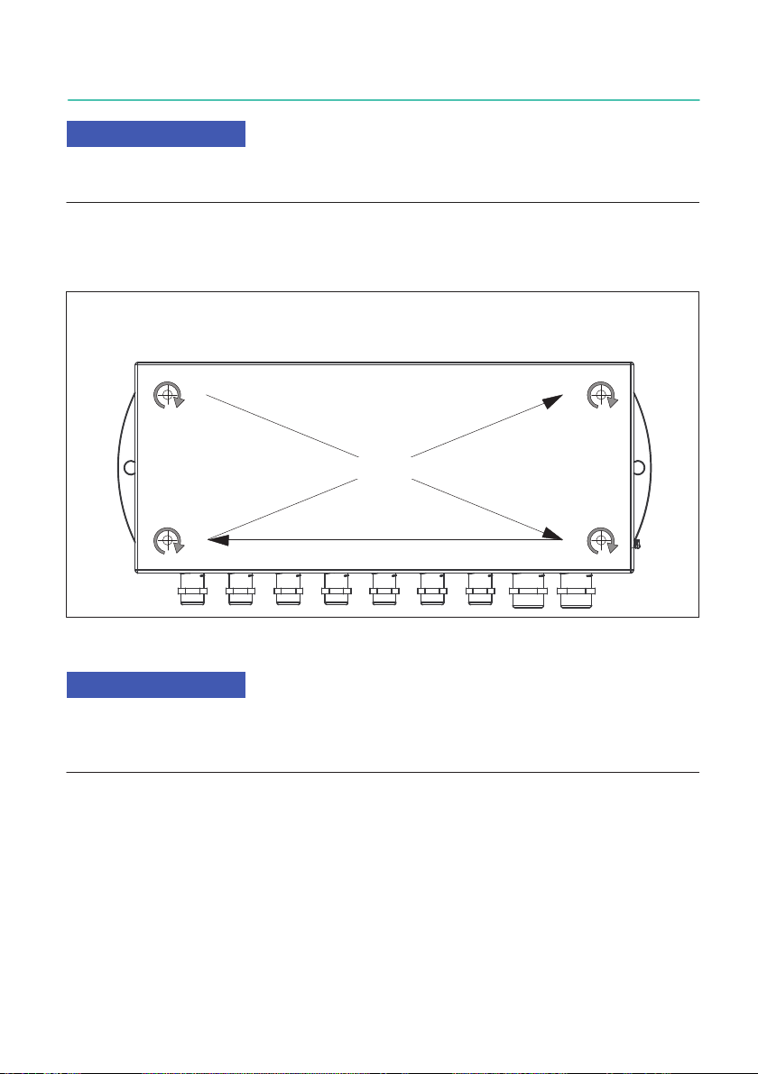
If you replace screwed cable glands, they must be tightened to a torque in accordance
with Tab. 5.1, page 8.
Maintenance
The junction box gives degree of protection IP65 (dust-tight, protected against water
jets). Make regular checks to ensure the tightness and efficiency of the rubber lid seal
and the screw fittings. The frequency of checks depends on the application conditions,
e.g. the level of contamination or the materials with which the junction box comes into
contact.
Disposal
Old junction boxes that can no longer be used must be disposed of in accordance with
national and local environmental protection and material recovery and recycling regula
tions.
If you need more information about waste disposal, please contact your local authorities
or the dealer from whom you purchased the product.
Qualified personnel
Qualified personnel means persons entrusted with siting, mounting, starting up and oper
ating the product, who possess the appropriate qualifications for their function.
This includes people who meet at least one of the three following requirements:
1. Knowledge of the safety concepts of automation technology is a requirement and as
project personnel, you must be familiar with these concepts.
2. As automation plant operating personnel, you have been instructed how to handle the
machinery. You are familiar with the operation of the equipment and technologies
described in this documentation.
3. As commissioning engineers or service engineers, you have successfully completed
the training to qualify you to repair the automation systems. You are also authorized
to activate, ground and label circuits and equipment in accordance with safety engin
eering standards.
It is also essential to comply with the legal and safety requirements for the application
concerned during use. The same applies to the use of accessories.
The junction box may only be installed by qualified personnel, strictly in accordance with
the specifications and with the safety requirements and regulations.

5
VKK2-8 / VKK2R-8
THE MARKINGS USED
2 THE MARKINGS USED
Important instructions for your safety are specifically identified. It is essential to follow
these instructions in order to prevent accidents and damage to property.
Symbol Significance
NOTICE This marking draws your attention to a situation in
which failure to comply with safety requirements can
lead to damage to property.
Important
This marking draws your attention to important in
formation about the product or about handling the
product.
Emphasis
See …
Italics are used to emphasize and highlight text and
identify references to sections, diagrams, or external
documents and files.
uThis marking indicates an action in a procedure

VKK2-8 / VKK2R-8
SPECIAL FEATURES
6
3 SPECIAL FEATURES
SParallel connection of max. eight load cells (VKK2-8, VKK2R-8) with six-wire configura
tion
SHBM's shielding Green-Line
SCorner load balancing via the integrated resistor network in the load cell output
SDegree of protection IP65 per EN 60529
SCan be expanded to connect more than eight load cells in parallel
The junction boxes also allow the shield to be connected conventionally by means of the
shield strands. With this method, EMC-proofing under EN 45501 is restricted, which can
lead to measurement errors if there are electromagnetic interference fields.
4 CONDITIONS ON SITE
Do not allow the junction box to become dirty or damp.

7
VKK2-8 / VKK2R-8
INSTALLING THE JUNCTION BOXES
5 INSTALLING THE JUNCTION BOXES
Notice
During installation and when connecting the cables, take action to prevent electrostatic
discharge as this may damage the connected electronics.
Install the junction boxes so that the cable glands face downwards. This makes it more
difficult for moisture to get in.
3.
Junction box viewed from above
Tighten the mounting screws in the following sequence:
1. 4.
2.
Tightening torque for the cover screws: 0.7N⋅m
Fig. 5.1 Sequence for tightening the mounting screws
Notice
Please tighten the lid screws with a torque of 0.7 NVm to ensure the specified IP degree of
protection and the highest possible EMC protection. The sealing washers under the lid
screws must not be removed.

VKK2-8 / VKK2R-8
INSTALLING THE JUNCTION BOXES
8
264.1
278
0
25
50
75
100
125
150
175
200
250
260
100
128
110
37.5 *
7x M12, a.f. 14 for cable Ø
3…6 mm, for explosion-
proof version 7x M12,
a.f.16 for cable Ø
3…6.5 mm
2x M16, a.f. 17 for cable Ø
5…9 mm, for explosion-
proof version 2x M16, a.f.20
for cable Ø 6…10 mm
* With rubber seal (mounted condition)
Mounting direction
∅7
Fig. 5.2 Mounting dimensions
Version Cable gland Across flats Tightening torque
Cap Connection
piece
Standard M12 x 1.5 14 3 Nm 6 Nm
M16 x 1.5 17 3 Nm 8 Nm
IECEx M12 x 1.5 16 3 Nm -
M16 x 1.5 20 3 Nm -
ATEX M12 x 1.5 16 3 Nm -
M16 x 1.5 20 3 Nm -
Tab. 5.1 Tightening torques of screwed cable glands

9
VKK2-8 / VKK2R-8
PREPARING THE CABLE
6 PREPARING THE CABLE
All the interconnecting cables must be shielded cables. The shield must be connected
extensively to ground on both sides.
6.1 Junction box without explosion protection VKK2-8A and VKK2R-8
Proceed as follows to achieve optimal results:
uRemove the outer sheath of the cable and expose approx. 10-15 mm of the braided
screen, depending on the cable diameter.
uPush the cap nut and bladed insert with gasket onto the cable.
uBend the braided screen outward at right angles (90°).
uCrimp the braided screen over towards the outer sheath of the cable, i.e. fold it an
other 180°.
uPush the intermediate connection piece on as far as the braided screen, turning it
rapidly to and fro around the cable axis.
uPush the bladed insert with gasket into the intermediate connection piece and engage
the locking element.
uTighten the cap nut to 3 Nm to ensure the degree of protection, while holding the
intermediate connection piece.
Shielded cable
Cap nut
Gasket
Intermediate
connection piece
Braided screen
Bladed insert
Fig. 6.1 Screwed clamping gland assembly

VKK2-8 / VKK2R-8
PREPARING THE CABLE
10
6.2 Junction box with explosion protection VKK2R-8 Ex
Before installation and commissioning
uCheck that the following are undamaged
-Ex device cable and cable entry
-Thread
-Gaskets and O-rings
-Threaded hole or through-hole in the housing
-Remove the dust protector
-Select the connection thread size based on the sealing and clamping area ØC
uMake sure the connection thread matches the threaded hole or through-hole in the
housing.
uPay attention to wall thicknesses
uCheck that the connection thread is sufficiently long. If necessary, select a variant with
long connection thread.
uWhen installing an Ex device cable and cable entry with long connection thread, and
when installing in the housing with hexagonal nuts, make sure the required air and
creepage distances are complied with.
Installing the PERFECT plus EMC Ex screwed cable gland
Only use the PERFECT plus EMC Ex screwed cable gland for shielding, not for potential
equalization.

11
VKK2-8 / VKK2R-8
PREPARING THE CABLE

VKK2-8 / VKK2R-8
PREPARING THE CABLE
12
During installation
uDuring installation, make sure that the Ex device cable and cable entry is fully screwed
into the connection thread.
uMake sure that seals are firmly seated.
uMake sure that the stated IP ratings are adhered to.
uIf necessary, use threadlocker fluid or an additional hexagonal nut to prevent screws
from working loose.
6.3 Junction box VKK2R-8IECEx
M12 cable gland
uStrip the cable.
uExpose the braided screen.
uRoute the cable through the swivel nut.
uInsert the cable in the bladed insert.
uPull the braided screen over the bladed insert.
uThe braided screen must cover approx. 2 mm of the O-ring.
uPush the bladed insert into the intermediate connection piece.
uTighten the cap nut to 3 Nm to ensure the degree of protection, while holding the
intermediate connection piece.

13
VKK2-8 / VKK2R-8
PREPARING THE CABLE
M16 cable gland
Variant 1 Variant 2 Variant 3
Variant 1 - If the braided screen and insulation continue
uStrip approx. 10 mm of the braided screen.
uInsert the cable in the cable gland until the braided screen reaches contact position.
uTurn the screwed cable gland to secure (see Tab. 5.1, page 8).
Variant 2 - If the braided screen continues
uStrip the desired length of the braided screen.
uInsert the cable in the cable gland until the braided screen reaches contact position.
uTurn the screwed cable gland to secure (see Tab. 5.1, page 8).
Variant 3 - If the braided screen terminates in the cable gland
uCut back the braided screen and insulation to form steps.
uIf the cable is thin, the braided screen can be pulled back over the insulation.
uInsert the cable in the cable gland until the braided screen reaches contact position.

VKK2-8 / VKK2R-8
CONNECTION
14
7 CONNECTION
Important
When connecting additional devices, comply with the safety requirements for electrical
measurement, control, regulatory and laboratory equipment (EN61010).
The terminals are identified as shown in the following diagram. The colors correspond to
the wire colors used for HBM load cells.
(white)
(black)
(gray)
Excitation voltage (+)
(green)
(red)
Excitation voltage (-)
Sense lead (-)
Measurement signal (+)
(blue)
Sense lead (+)
Measurement signal (-)
Cable shield
(connected to the housing)
Cable assignment (six-wire configuration)
To achieve the best-possible measurement results and to optimize interference
immunity, connect to the weighing electronics with HBM cables using a 6-wire configura
tion.
If the load cells and weighing electronics laid out in four-wire configuration, the terminals
for the sense leads remain free.
If the load cells are in four-wire configuration and the weighing electronics in six-wire con
figuration, the terminals for the sense leads (+) must be bridged with those for the excita
tion voltage (+) and the terminals for the sense leads (-) bridged with those for the excita
tion voltage (-) (see the installation instructions for the load cells used).
Important
All unused cable glands must be closed off with the plugs provided for the purpose.
Tighten the associated sleeve nut in each case to stop moisture penetrating.

15
VKK2-8 / VKK2R-8
PARALLEL CONNECTION, MORE THAN 8 LOAD CELLS
8 PARALLEL CONNECTION, MORE THAN 8 LOAD CELLS
Important
Not permitted for applications in potentially explosive atmospheres.
Load cells 1 ... 8
Please note:
Unused cable glands must be fitted with blind plugs.
The connection cable between junction box 1 and junction box 2 must be as short as
possible.
1234 8567
Output 1)
1234 8567
Output 2)
Load cells 9 ... (15)
Output 1) = Connection to junction box 2
Output 2) = Output to weighing electronics
Junction box 1 Junction box 2
Fig. 8.1 Example: Parallel connection of more than 8 load cells with 2 VKK0

VKK2-8 / VKK2R-8
OFF-CENTER LOAD COMPENSATION
16
9 OFF-CENTER LOAD COMPENSATION
With weighing machines, mechanical imbalance may lead to off-center load errors.
According to the EN 45501 3.6.2 standard for non-automatic weighing machines, specific
values are to be maintained for eccentric loading.
The junction boxes provide an easy way to compensate for these errors electrically. A
binary-stepped network of 5 resistors is available for each load cell, that is shorted at the
factory via 0Ω resistors (see Fig. 9.1). Opening the vertical 0Ω ohm resistors activates
the relevant resistances and thus reduces the load cell signal.
0,22 Ω
0,39 Ω
87 21
Output
Measuring
amplifier
Imput
Load cells 1 ... 8
0,82 Ω
1,50 Ω
3,00 Ω
0,22 Ω
0,39 Ω
0,82 Ω
1,50 Ω
3,00 Ω
0,22 Ω
0,39 Ω
0,82 Ω
1,50 Ω
3,00 Ω
0,22 Ω
0,39 Ω
0,82 Ω
1,50 Ω
3,00 Ω
Sense lead (+)
Ex. voltage (-)
Ex. voltage. (+)
Sense lead (-)
Measurement
signal (-)
Measurement
signal (+)
Fig. 9.1 Resistor network for corner load balancing of 8 load cells

17
VKK2-8 / VKK2R-8
TECHNICAL RECOMMENDATIONS
10 TECHNICAL RECOMMENDATIONS
Practical example using a platform with 4 load cells:
SWhen the four corners of the platform are loaded, note the scale signals in order to
assess the respective differences (in kg) to the corner of the scale (load cell) with the
lowest indication. This load cell is the reference load cell (4) and does not need balan
cing (in the example in Fig. 10.1, load cell 4).
SThe diagram (Fig. 10.2) is graduated in 7 test load ranges. Select the test loads used
(12.5 t in the example) in the relevant line. Starting from the calculated off-center load
error difference on the X-axis, look for the intersection with the test load and then, on
the Y-axis, read off the resistance and the most suitable combination. The resistance
values here apply for 350Ω load cells (see the table in the lid of the VKK...).
In our example, load cell 3 has a corner load error of 80 kg, which produces an adjust
ment resistance of 1.5 + 0.82Ω (shown in Fig. 10.2).
Load cell 1
12,600 kg
Load cell 2
12,550 kg
Load cell 3
12,530 kg
Reference load cell 4
12,450 kg
Test load
12.5 t
(Example: Reference load cell +80 kg)
Fig. 10.1 Example: Platform weighing machine with four load cells with 12.5 t test load
SFor the load cell affected (e.g. load cell 3), the necessary resistances are activated by
opening the relevant “0Ω resistor”: Divide the wire and bend it to one side.
SRepeat this procedure for all the load cells apart from the “reference load cell”(load
cell 4 in the example).

VKK2-8 / VKK2R-8
TECHNICAL RECOMMENDATIONS
18
3+1,5+0,82+0,39
3+1,5+0,39+0,22
3+0,22
3+1,5+0,82+0,39+0,22
1
10
100
0,2
2
20
80
0,22
0,39
0,39+0,22
0,82
0,82+0,22
0,82+0,39
0,82+0,39+0,22
1,5
1,5+0,22
1,5+0,39
1,5+0,39+0,22
1,5+0,82
1,5+0,82+0,22
1,5+0,82+0,39
3
1,5+0,82+0,39+0,22
3+0,39
3+0,39+0,22
3+0,82
3+0,82+0,22
3+0,82+0,39
3+0,82+0,39+0,22
3+1,5
3+1,5+0,22
3+1,5+0,39
3+1,5+0,82
3+1,5+0,82+0,22
Off-center lead error in kg
Example:
Test load: 12.5 t
Corner load error: 80 kg
50 kg
0,5 t
5 t
Test load
Resistor of your
choice
2
20
200
3
30
300
4
40
400
5
50
500
100 kg
1 t
10 t
125 kg
1,25 t
12,5 t
150 kg
1,5 t
15 t
200 kg
2 t
20 t
250 kg
2,5 t
25 t
300 kg
3 t
30 t
Adjustment resistance R in ohms
Fig. 10.2 Off-center load compensation for for 350Ω load cells (for 700Ω load cells, the
established value must be doubled)
This manual suits for next models
3
Table of contents
Languages:
Other NBK Industrial Equipment manuals
Popular Industrial Equipment manuals by other brands

Multi-Mover
Multi-Mover 3XL 40TO User manual and parts list

Terex
Terex Genie SHOV50014B-1001 Operator's manual

PERGO
PERGO SCHWAMMFIX POWER SPONGE 620P User & Safety Instructions

Simon, Evers & Co
Simon, Evers & Co KK 658287 operating manual

Tomco
Tomco DE89RB100-US Operation & maintenance manual

Aventics
Aventics MSC Series RE-ASSEMBLY INSTRUCTIONS