NEC VERSA DOCK - SERVICE User manual

First Printing — August 1998
Copyright 1998
NEC Computer Systems Division
Packard Bell NEC, Inc.
1 Packard Bell Way
Sacramento, CA 95828-0903
All Rights Reserved
Proprietary Notice and Liability Disclaimer
The information disclosed in this document, including all designs and related materials, is the
valuable property of NEC Computer Systems Division, Packard Bell NEC, Inc. (hereinafter
“NECCSD”) and/or its licensors. NECCSD and/or its licensors, as appropriate, reserve all patent,
copyright and other proprietary rights to this document, including all design, manufacturing,
reproduction, use, and sales rights thereto, except to the extent said rights are expressly granted to
others.
The NECCSD product(s) discussed in this document are warranted in accordance with the terms of
the Warranty Statement accompanying each product. However, actual performance of each such
product is dependent upon factors such as system configuration, customer data, and operator
control. Since implementation by customers of each product may vary, the suitability of specific
product configurations and applications must be determined by the customer and is not warranted
by NECCSD.
To allow for design and specification improvements, the information in this document is subject to
change at any time, without notice. Reproduction of this document or portions thereof without prior
written approval of NECCSD is prohibited.
FaxFlash is a service mark of NEC Computer Systems Division (NEC CSD), Packard Bell NEC, Inc.
NEC is a registered trademark of NEC Corporation, used under license.
ENERGY STAR is a U.S. registered mark.
All other product, brand, or trade names used in this publication are the trademarks or registered trademarks of their
respective trademark owners.

Preface v
Preface
This service and reference manual contains the technical information necessary to set up
and maintain the NEC Versa ® Dock, for use with the NEC Versa LX and SX notebook
computers.
The manual also provides hardware and interface information for users who need an
overview of the system design. The manual is written for NEC-trained customer engineers,
system analysts, service center personnel, and dealers.
The manual is organized as follows:
Section 1, System Overview, provides an overview of the hardware and interface
components.
Section 2,System Configuration and Setup, provides information on setup and how to
operate the docking station.
Section 3,Disassembly and Reassembly, provides detailed instructions on how to
disassemble and reassemble the docking station.
Section 4,System Board Layout and Board Connectors, shows the system boards and the
board connectors.
Section 5, Illustrated Parts Breakdown, shows the Illustrated Parts Breakdown (IPB) and
corresponding part numbers.
Section 6, Preventive Maintenance, lists general docking station preventive maintenance
procedures.
Section 7, Troubleshooting, lists troubleshooting procedures as well as helpful servicing
hints.
Section 8, Support, provides information as to how to contact NEC CSD for service
information, technical support, product information and ordering information from
FaxFlash.
Section 9, Specifications, lists physical specifications.
An Index is included for convenience.

vi
Aampere
AC alternating current
AT advanced technology
(IBM PC)
BBS Bulletin Board Service
BCD binary-coded decimal
BCU BIOS Customized Utility
BIOS basic input/output system
bit binary digit
BUU BIOS Upgrade Utility
bpi bits per inch
bps bits per second
Ccapacitance
Ccentigrade
Cache high-speed buffer storage
CAM constantly addressable
memory
CAS column address strobe
CD/ROM compact disk-ROM
CG character generator
CGA Color Graphics Adapter
CGB Color Graphics Board
CH channel
clk clock
cm centimeter
CMOS complementary metal oxide
semiconductor
COM communication
CONT contrast
CPGA ceramic pin grid array
CPU central processing unit
DAC digital-to-analog converter
DACK DMA acknowledge
DC direct current
DIP dual in-line package
DLAB Divisor Latch Address bit
DMA direct memory access
DMAC DMA controller
DOS disk operating system
DRAM dynamic RAM
ECC error checking and correction
EDO extended data output
EGA Enhanced Graphics Adapter
EPROM erasable and programmable
ROM
EVGA Enhanced Video Graphics
Array
FFahrenheit
FAX facsimile transmission
FCC Federal Communications
Commission
FG frame ground
FM frequency modulation
FP fast page
FRU field-replaceable unit
GB gigabyte
GND ground
HEX hexadecimal
HGA Hercules Graphics Adapter
Hz hertz
IC integrated circuit
ID identification
IDE intelligent device electronics
IDTR interrupt descriptor table
register
in. inch
INTA interrupt acknowledge
IPB illustrated parts breakdown
IR infrared
IRR Interrupt Request register
ISA Industry Standard
Architecture
ISR In Service register
I/O input/output
Abbreviations

vii
IPC integrated peripheral
controller
ips inches per second
IRQ interrupt request
Kkilo (1024)
kkilo (1000)
KB kilobyte
kg kilogram
kHz kilohertz
lb pound
LED light-emitting diode
LSB least-significant bit
LSI large-scale integration
Mmega
mA milliamps
max maximum
MB megabyte
MDA Monochrome Display Adapter
MFM modified frequency
modulation
MHz megahertz
mm millimeter
ms millisecond
MSB most-significant bit
NASC National Authorized Service
Center
NC not connected
NMI Non-maskable Interrupt
ns nanosecond
NSRC National Service Response
Center
PAL programmable array logic
PCB printed circuit board
PCI Peripheral Component
Interconnect
PDA personal digital assistant
PFP plastic flat package
PIO parallel input/output
pixel picture element
PLCC plastic leaded chip carrier
PLL phase lock loop
p-p peak-to-peak
PPI programmable peripheral
interface
PROM programmable ROM
QFP quad flat pack
RAM random-access memory
RAMDAC RAM digital-to-analog
converter
RAS row address strobe
RGB red green blue
RGBI red green blue intensity
ROM read-only memory
rpm revolutions per minute
Rread
RTC real-time clock
R/W read/write
Sslave
SCSI Small Computer System
Interface
SG signal ground
SIMM single inline memory module
SPM standard page mode
SRS Sound Retrieval System
SVGA Super Video Graphics Array
SW switch
TAC Technical Assistance Center
TSC Technical Support Center
TTL transistor/transistor logic
tpi tracks per inch
USB universal serial bus
Vvolt
Vac volts, alternating current
Vdc volts, direct current
VESA video electronics standards
association
VFC VESA-compliant feature
connector
VGA Video Graphics Array
VRAM video RAM
Wwatt
Wwrite

Contents iii
Contents
Preface .....................................................................................................................................v
Abbreviations......................................................................................................................... vi
1Introducing the NEC Versa Dock
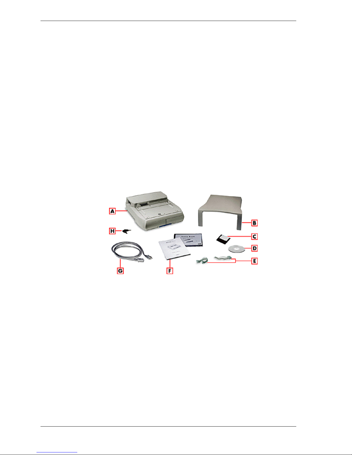
Carton Contents.....................................................................................................................1-2
NEC Versa Dock Features.....................................................................................................1-3
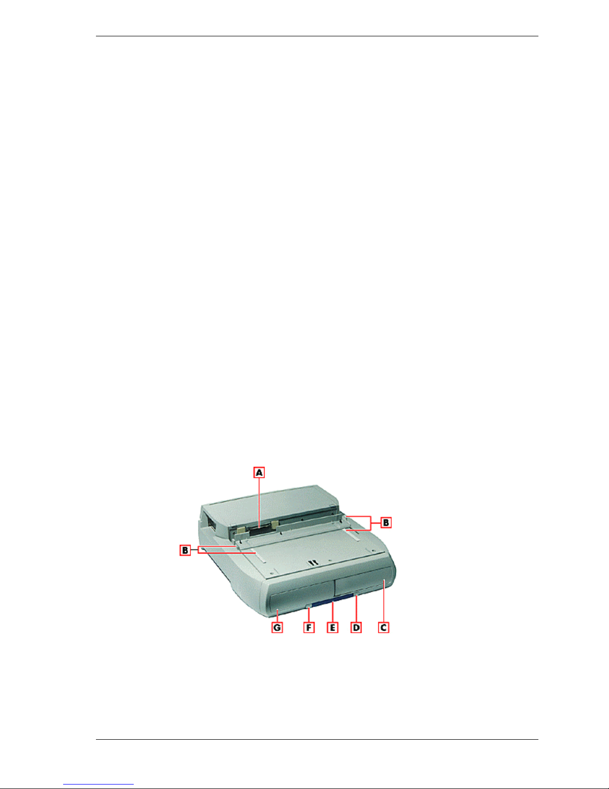
Front and Top..............................................................................................................1-3
Left Side......................................................................................................................1-6
Right Side....................................................................................................................1-7
Back............................................................................................................................1-8
The Right Environment..........................................................................................................1-9
Operating Environment................................................................................................1-9
Storage Environment ...................................................................................................1-9
2System Configuration and Setup
Setting Up Software...............................................................................................................2-2
Updating the BIOS ......................................................................................................2-2
Installing Drivers.........................................................................................................2-4
Installing the Online User’s Guide ...............................................................................2-5
Docking and Undocking ........................................................................................................2-6
Connecting the Power Cable........................................................................................2-6
Preparing the NEC Versa for Docking .........................................................................2-7
Docking the NEC Versa...............................................................................................2-9
Locking the NEC Versa.............................................................................................2-13
Undocking the NEC Versa.........................................................................................2-15
Emergency Undocking...............................................................................................2-17
Installing Options and Connecting Devices..........................................................................2-18
Installing Devices in the File Bays.............................................................................2-19
Installing PCI Cards...................................................................................................2-32
Installing PC (PCMCIA) Cards..................................................................................2-34
Connecting External Devices.....................................................................................2-35
3Disassembly and Reassembly
Required Tools and Equipment..............................................................................................3-2
Disassembly ..........................................................................................................................3-2
Preparation for Disassembly ........................................................................................3-3
Removing Trays, Panels and Covers............................................................................3-3
Disconnecting the Cables from the Motherboard..........................................................3-6
Removing Device Brackets..........................................................................................3-7
Back Cover, Left and Right Sides, and Top Cover .......................................................3-8
Docking Connector Board, PCI Housing, and Power Supply........................................3-9
Docking Tray Assembly and Motor Assembly...........................................................3-12
Main Board Assembly ...............................................................................................3-13
Reassembly .........................................................................................................................3-14

iv Contents
4System Board Layout
Main Board ...........................................................................................................................4-2
LED Board............................................................................................................................4-2
PCI Expansion Board.............................................................................................................4-2
5Illustrated Parts Breakdown
NEC Versa Dock Illustrated Parts Breakdown........................................................................5-2
Parts List...............................................................................................................................5-3
6Preventive Maintenance
Precautions............................................................................................................................6-2
Battery Charging ...................................................................................................................6-2
Routine Care..........................................................................................................................6-3
Cleaning the Versa Dock Interior...........................................................................................6-3
Protecting the Disk Drives .....................................................................................................6-4
7Troubleshooting
Quick Troubleshooting ..........................................................................................................7-2
Helpful Questions..................................................................................................................7-4
8Getting Services and Support
Services and Support Contact Information .............................................................................8-2
NEC NOW............................................................................................................................8-3
NEC CSD Web Site...............................................................................................................8-3
NEC CSD FTP Site ...............................................................................................................8-4
NEC CSD FaxFlash Service...................................................................................................8-4
Email/Fax to Support Services...............................................................................................8-5
NEC CSD Bulletin Board ......................................................................................................8-6
NEC CSD Support Services...................................................................................................8-7
NEC CSD Customer Assistance Center..................................................................................8-8
Versa Laptop Fulfillment Hotline...........................................................................................8-8
9Specifications
Features.................................................................................................................................9-2
Input/Output Facilities...........................................................................................................9-2
Expansion Capabilities...........................................................................................................9-3
Indicator LEDs......................................................................................................................9-3
Power Supply ........................................................................................................................9-3
Power Cables.........................................................................................................................9-4
Dimensions............................................................................................................................9-4
Environmental Requirements.................................................................................................9-4
Glossary
Index

1
Introducing the NEC Versa Dock
nCarton Contents
nNEC Versa Dock Features
nThe Right Environment

1-2 Introducing the NEC Versa Dock
The NEC Versa Dock lets you maximize your NEC Versa LX and SX
capabilities without minimizing portability. Connect an external monitor and
keyboard to the ports on the back of the NEC Versa Dock, install your
CD-ROM reader in the optional NEC Versa Dock VersaBay III adapter kit,
attach your joystick to the MIDI/Game port, and you're ready to work hard or
play! Undock the NEC Versa from the NEC Versa Dock and you're ready for
the road.
This chapter introduces NEC Versa Dock features, guides you to choosing the
correct environment.
Carton Contents
Unpack and check the contents of the NEC Versa Dock carton.
Be sure you have the hardware components shown in the following figure and
that they are in good condition. If anything is damaged or missing, contact your
dealer immediately.
Carton Contents
A- NEC Versa Dock B- CRT base C- BIOS update diskette
D - Software Setup CD E- IDE power cables F- User documentation
G - AC power cable H- NEC Versa Dock keys
nNEC Versa Dock — provides many features to expand your NEC Versa
capabilities. These features are described in detail in this chapter.
nCRT Base — supports an external monitor that weighs up to 55 lb (25
kg).
nBIOS update diskette.
nNEC Versa Dock Software Setup CD.
nTwo extra power cables for the installation of optional IDE devices.

Introducing the NEC Versa Dock 1-3
nUser Documentation — introduces you to the NEC Versa Dock and
guides you through initial docking and setup.
nAC Power Cable — allows you to connect your NEC Versa Dock to AC
power.
Always use the power cable that ships with the NEC Versa Dock. If you
need to replace the cable, follow these standards:
In North America, the cable should be rated for 120 volts (V), 7
amps(A). The plug is a NEMA 5-15P. Use an SVT or SJT 18/3 AWG
cable that is less than 15 feet (4.5 m) long. Use connector type
IEC320.
In Europe, the cable should be rated for 230 V (220-240 V), 10A. The
plug is country-specific. Use an H05VV-F or H05VVH2-F cable that
is less than 15 feet (4.5 m) long. Use connector type EN60320.
nNEC Versa Dock Keys.
NEC Versa Dock Features
NEC Versa Dock features are found on all sides of the unit. To become familiar
with these features, read each of the following sections.
Front and Top
The following figure shows the features found on the front and top of the NEC
Versa Dock. Descriptions of these features follow the figure.
Front and top features
A- Docking connector B- Docking guides C- Right file bay
D- Power button E- Status LEDs F- Dock/Undock button
G- Left file bay

1-4 Introducing the NEC Versa Dock
nDocking Connector — Fits the expansion port on your NEC Versa to
allow for docking.
nDocking Guides — Ensure that your NEC Versa is aligned properly for
docking. These guides provide positioning for docking with the monitor
stand in place.
nTwo File Bays — Allows you to install IDE file devices in your NEC
Versa Dock.
The left file bay supports any 5.25-inch IDE device (like a tape drive,
hard disk drive, or SuperDisk drive.) It also supports 3.5-inch IDE
devices with a 3.5-inch Universal Installation Kit.
The right file bay is identical to the left file bay, with the added
versatility that allows you to install the optional VersaBay III Adapter
Kit. With the VersaBay III Adapter kit installed, you can use any of
your VersaBay III options in the file bay.
nPower Button — Allows you to power on and off the NEC Versa LX or
SX notebook computer while docked on the NEC Versa Dock.
nStatus LEDs — LEDs on the front of the unit inform you of the docking
status, keylock status, IDE drive access, diskette drive access, and battery
charge status (for a battery installed in the optional VersaBay III Adapter
Kit). LEDs are shown in the following figure and LED states are
described after the figure.
Status LEDs
A- Docking status LED B- Keylock status LED C- IDE access LED
D- Diskette drive access LED E- Battery charge status LED

Introducing the NEC Versa Dock 1-5
Hot docking and hot undocking is supported with Plug-and-
Play operating systems, such as Windows 95. Before hot
undocking, the docking/undocking button must be pressed
or you must select Eject PC from the Windows 95 Start
button. May not be supported on all systems.
Docking Status – lights as follows:
–Steady Yellow – AC power is on, the keylock switch is in the
Normal position, and the NEC Versa Dock is ready for docking.
–Steady Green – The NEC Versa is docked on the NEC Versa Dock
and is either powered on or in Standby mode.
–Fast Blinking Amber – A docking or undocking error has occurred or
the docking tray is in the wrong position for the system.
–Off – AC power is on, the keylock is in the Manual or Locked
position, and either no NEC Versa is docked or the NEC Versa is
docked and powered off.
Keylock Status – Lights as follows:
–Off – No NEC Versa is docked.
–Steady Amber – The NEC Versa is docked but not locked on the
NEC Versa Dock. The key is in either the Normal position with the
notebook turned off, or in the Manual position with the notebook on
or off.
–Steady Yellow – The NEC Versa is locked onto the NEC Versa Dock
through software. The key is in the Normal position and the NEC
Versa is on.
–Steady Green – The NEC Versa is physically locked onto the NEC
Versa Dock. The key is in the Lock position with notebook power on
or off.
IDE Drive Access – lights as follows to indicate access to an IDE device
such as a CD-ROM, hard disk or SuperDisk drive installed in an NEC
Versa Dock file bay, an optional VersaBay III Adapter Kit, or in the
NEC Versa.
–Off – No IDE device is being accessed.
–Green – The NEC Versa is accessing the IDE drive.
Diskette Drive Access – Lights as follows to indicate access to a floppy
disk drive installed in the NEC Versa notebook computer only.
–Off – No diskette drive is being accessed.

1-6 Introducing the NEC Versa Dock
–Green – The NEC Versa is accessing the diskette drive.
Battery Charge Status – Lights as follows to indicate the battery charge
to a secondary battery pack installed in the optional VersaBay III
Adapter Kit.
–Steady Green – The battery installed in the optional VersaBay III
Adapter Kit is being charged. You can charge the battery whether the
NEC Versa Dock is powered on or off or is in Standby mode. You
can also charge the battery in the optional VersaBay III Adapter Kit
when no system is docked in the NEC Versa Dock. The NEC Versa
Dock must be connected to an AC power source to charge the battery
pack.
–Off – The installed battery is fully charged, or no battery is installed.
nDocking/Undocking Button — Initiates the automatic sequence for
docking or undocking your system if the keylock is in the normal
position.
Left Side
Features found on the left-hand side of the NEC Versa Dock are shown in the
following figure. Features are described after the figure.
Left side features
A- PCI external access B- Height lever C- Volume control knob
D- Audio ports E- MIDI/Game port
nPCI External Access — Gives you access to external ports, connectors,
switches and indicators on installed PCI cards.
nHeight Adjustment Lever — Adjusts the height on the docking tray to
match the height of your system. To access the lever, pull the door open
by the slot.
nVolume Control — Gives you control over the volume of external
speakers or headphones attached to the NEC Versa Dock.

Introducing the NEC Versa Dock 1-7
nAudio Ports — Connects external audio devices including a microphone,
headphones, or speakers. You can also connect other audio devices to use
as an output device or input source.
nMIDI/Game Port — Supports MIDI/Game devices, such as a joystick or
MIDI keyboard.

1-8 Introducing the NEC Versa Dock
Right Side
The keylock switch on the right side of the NEC Versa Dock is shown in the
following figure. A description follows the figure.
Right side feature
A- Keylock switch
nKeylock switch — Provides three settings that let you control NEC Versa
removal. An alarm sounds if someone tries to remove the NEC Versa
while it is locked onto the NEC Versa Dock, even if the NEC Versa Dock
is powered off or is disconnected from AC power.
Motorized docking is only enabled when the keylock switch
is in the full upright position.
Locked – Prevents the NEC Versa from being removed from the NEC
Versa Dock. You must use the key to unlock the unit before removing
the NEC Versa.
Normal – (Default position). Allows you to motorize dock or undock
the NEC Versa. Set the keylock to this position for normal use. To
prevent electrical damage, manual undocking is not allowed when the
keylock is in this state.
Manual – Allows you to remove the NEC Versa by hand. Use the
unlocked position for emergency undocking only. Otherwise, use the
Normal lock setting for normal use and the Locked setting to
physically secure your system to the NEC Versa Dock.
If no computer is docked and the keylock is in the Locked position,
no one else can use their computer with the NEC Versa Dock. The
key can only be removed from the system while the keylock is in the
Locked position.

Introducing the NEC Versa Dock 1-9
Back
Features on the back of the NEC Versa Dock are shown in the following figure.
Descriptions follow the figure.
Back features
A- Fan assembly B- Voltage selector switch C- Keyboard port
D- Kensington lock port E- USB ports F- Parallel port
G- Serial port H- Monitor port I- Mouse port J- AC power port
nFan Assembly — Provides proper cooling for the power supply that
regulates power in the NEC Versa Dock. Keep the fan assembly clear of
obstructions to ensure proper cooling.
nVoltage Selector — Allows you to choose from 115 or 230 Volts.
nPS/2-style Keyboard Port — Allows you to connect an external keyboard
to the NEC Versa Dock.
nKensington Lock Port — Allows you to secure your NEC Versa Dock
using an optional Kensington Lock.
nUSB Ports — Allows you to connect Universal Serial Bus devices to the
NEC Versa Dock.
nParallel Port — Allows you to connect a parallel device to the NEC Versa
Dock.
nSerial Port — Allows you to connect a serial device to the NEC Versa
Dock.
nExternal Monitor Port — Allows you to connect an external monitor to
the NEC Versa Dock. (You may need to press Fn-F3 to get an image on
the external monitor. See your NEC Versa User’s Guide for function key
combinations.)
nPS/2-style Mouse Port — Allows you to connect an external mouse to the
NEC Versa Dock.
nPower Port — Allows you to connect the NEC Versa Dock to AC power.

1-10 Introducing the NEC Versa Dock
The Right Environment
Before setting up the NEC Versa Dock, find a good location for its use. Here are
some guidelines.
nChoose an area close to a wall outlet that is easily accessible.
nSelect a flat, sturdy surface, like a desktop or table, so you have access to
the front, back, and sides of the unit.
nChoose an area away from extreme temperatures, direct sunlight,
excessive dust, vibration, shock or moisture.
Operating Environment
Use the NEC Versa Dock in a location that meets the following environmental
conditions:
nTemperature: 41°F to 95°F (5°C to 35°C)
nHumidity: 20% to 80% (non-condensing)
Storage Environment
Store the NEC Versa Dock in a location that meets the following conditions:
nTemperature: –4°F to 122°F (–20°C to 50°C)
nHumidity: 15% to 85% (non-condensing)

2
System Configuration and Setup
nSetting Up Software
nDocking and Undocking
nInstalling Options and Connecting Devices

2-2 System Configuration and Setup
Setting Up Software
Before docking the NEC Versa in the NEC Versa Dock, be sure to prepare your
NEC Versa notebook computer for use in the NEC Versa Dock. This involves
three procedures.
nFlashing the NEC Versa notebook computer’s BIOS, using the correct
BIOS Update for your NEC Versa.
nInstalling the drivers on the NEC Versa notebook computer, using the
NEC Versa Dock Software Setup CD.
nInstalling the Online User Guide using the NEC Versa Dock Software
Setup CD.
Instructions for installing each of these software utilities can be found in the
following sections.
Updating the BIOS
To update your system BIOS, choose the correct BIOS update for your NEC
Versa that is provided on the BIOS Update diskette.
nNEC Versa SX with Pentium I — choose the BIOS Update for the NEC
Versa SX Series with Pentium I.
nNEC Versa SX with Pentium II — choose the BIOS Update for the NEC
Versa SX Series with Pentium II.
nNEC Versa LX with Pentium I — choose the BIOS Update for the NEC
Versa LX Series with Pentium I.
nNEC Versa LX with Pentium II — choose the BIOS Update for the NEC
Versa LX Series with Pentium II.
Use only the BIOS update diskette included with the NEC Versa Dock and be
sure to prepare the diskette before upgrading the BIOS.
Preparing the BIOS Update Diskette
Before using the BIOS update diskette, you must make the diskette BIOS flash
ready. Refer to the readme.txt file on the diskette before using the diskette.
Follow these instructions to prepare the BIOS Update Diskette.
1. Scan your hard drive for any computer viruses.
1. Enable the diskette for write access by sliding the write-protect tab to the
write-enabled setting.
1. Insert the diskette into drive A:.
1. Type a:\install at the DOS prompt and follow the on-screen instructions.
Install.bat copies the DOS system files from your hard drive onto the BIOS
Update Diskette to make it BIOS flash ready.

System Configuration and Setup 2-3
The system prompts you when the process is complete.
1. Scan the BIOS Update Diskette for computer viruses.
The diskette is ready for use.
6. Follow the instructions below for performing the actual BIOS update.
Performing the BIOS Update
Use the following procedure to perform the actual BIOS update.
1. Make sure the NEC Versa is operating under AC power, and that the power
is off. Insert the BIOS Update diskette into diskette drive A.
1. Power on the computer with the diskette in drive A. The computer boots and
automatically loads the utility. A message similar to the following appears:
The NEC BIOS Update Utility should not be used to modify the BIOS in a Versa system
which is docked. If your NEC Versa is docked, please exit the BIOS Update Utility,
power down, and undock your NEC Versa before running the utility. Plug in your power
cable before restarting the flash utility.
1. Press Enter to continue.
The utility checks the currently installed BIOS version and the diskette’s
BIOS version. The Main menu appears.
1. Use the arrow keys to highlight the “Display BIOS Version” option on the
Main menu. Use this option to check the currently installed BIOS version
and the version of the new replacement BIOS.
1. Highlight the “Install New BIOS” option and press Enter.
1. Press Yand then press Enter. After a brief pause, a message appears telling
you to remove the diskette in drive A.
1. Remove the diskette and press any key to continue. The utility updates the
BIOS.
Power off your computer. The next time you power on your computer, you
will have the latest NEC Versa LX or SX computer BIOS revision level.
8. Enter Setup to restore the default parameter settings.

2-4 System Configuration and Setup
Installing Drivers
The drivers for the NEC Versa Dock can be found on the NEC Versa Dock
Software Setup CD. Refer to the readme.txt file on the CD for details on driver
installation for the NEC Versa Dock.
The Software Setup CD dialog box consists of the following components.
nSelection Tabs — Located just below the title bar, each tab represents a
software category.
nDescription — Located in the bottom portion of the dialog box, the text
describes the selected or highlighted software category or driver.
nInstall — Clicking the Install button installs the selected software.
nExit — Clicking the Exit button closes the NEC Versa Dock Software
Setup CD dialog box.
Once the NEC Versa Dock Software Setup CD dialog box appears, follow these
steps to install the desired software.
1. Insert the NEC Versa Dock Software Setup CD into the CD-ROM reader.
If you have a combination of two CD-ROM devices installed
in the NEC Versa and the NEC Versa Dock, be sure you
have the NEC Versa Dock Software Setup CD in the CD-
ROM drive that was installed first and has the lowest
assigned drive letter (such as D:\ or E:\).
2. From the Start menu, type Run.
2. Click the Browse button to access the Setup.exe file on the CD.
4. Click the selection tab of your choice.
4. Click the plus (+) box beside the desired utility to expand the selection.
4. Click the Installation selection to activate the Install button.
4. Click the Install button to install your selection.
4. Click Exit to close the NEC Versa Dock Software Setup CD dialog box.
Follow the on-screen instructions to install your selection.
9. Remove the CD from the CD-ROM reader when the installation is complete.
Other manuals for VERSA DOCK - SERVICE
3
Table of contents
Other NEC Computer Accessories manuals

NEC
NEC VERSA DOCK - SERVICE User manual

NEC
NEC VERSA MINIDOCK 6000 User manual

NEC
NEC VERSA DOCKING STATION 6000 User manual

NEC
NEC VERSA DOCK - SERVICE Operating manual

NEC
NEC POWERMATE DESKTOP - INSTALLATION ZIP DRIVE User manual

NEC
NEC IE-703217-G1-EM1 User manual

NEC
NEC N8101-616F User manual

NEC
NEC VERSA MINIDOCK 6000 User manual

NEC
NEC VERSA MEDIADOCK - SERVICE User manual