NEC QX-S6648XP-6Q User manual

GVT-052856-001-00 1.1
QX-S6600 Series Ethernet Switches
Installation Guide

Revision History
Revision Date Reason for Change
1.1 2018/03 First Revision

Copyright © NEC Corporation 2018
All Rights Reserved
No part of this manual may be reproduced or transmitted in any form or by any
means without prior written consent of NEC Corporation.
Trademarks
All other trademarks that may be mentioned in this manual are the property of their
respective owners.
Notice
The information in this document is subject to change without notice. Every effort
has been made in the preparation of this document to ensure accuracy of the
contents, but all statements, information, and recommendations in this document do
not constitute the warranty of any kind, express or implied.

Preface
Version
This installation guide corresponds after software version 7.1.X.
Documentation Set
The Documentation Set of QX-S6600 Series Ethernet Switches includes the
following documentations.
Documentation Set Description
QX-S6600 Series Ethernet
Switches Installation Guide This documentation describes installation.
QX-S6600 Series Ethernet Switches
Configuration Guides This documentation describes configuration.
QX-S6600 Series Ethernet Switches
Command References This documentation describes commands.
Sections
This installation guide includes the following 11 sections.
Product overview
The Product overview describes commands for QX-S6600 Series panel views.
Preparing for installation
The Preparing for installation describes commands for Safety recommendations,
Examining the installation site, Temperature/humidity, etc.
Installing the switch
The Installing the switch describes commands for Installing, Mounting, Grounding,
etc.
Accessing the switch for the first time
The Accessing the switch for the first time describes commands for Setting up the
configuration environment, Connecting, etc.
Setting up an IRF fabric
The Setting up an IRF fabric describes commands for IRF fabric setup flowchart,
Planning and Connecting IRF fabric, etc.

Upgrading software
The Upgrading software describes the type of the software used by the switch,
during movement or upgrade method when normally not starting.
Maintenance and troubleshooting
The Maintenance and troubleshooting describes commands for Power module
failure, Fan failure, etc.
Appendix A Technical specifications
The Appendix A Technical specification describes commands for Technical
specifications.
Appendix B FRUs and compatibility matrixes
The Appendix B FRUs and compatibility matrixes describe commands for Hot
swappable power modules, Hot swappable fan trays.
Appendix C Ports and LEDs
The Appendix C Ports and LEDs describe commands for Ports, UTP cables, LEDs,
etc.
Appendix D Cooling system
The Appendix D Cooling system describes commands for QX-S6600 Series cooling
system.
Conventions
This section describes the conventions used in this documentation set.
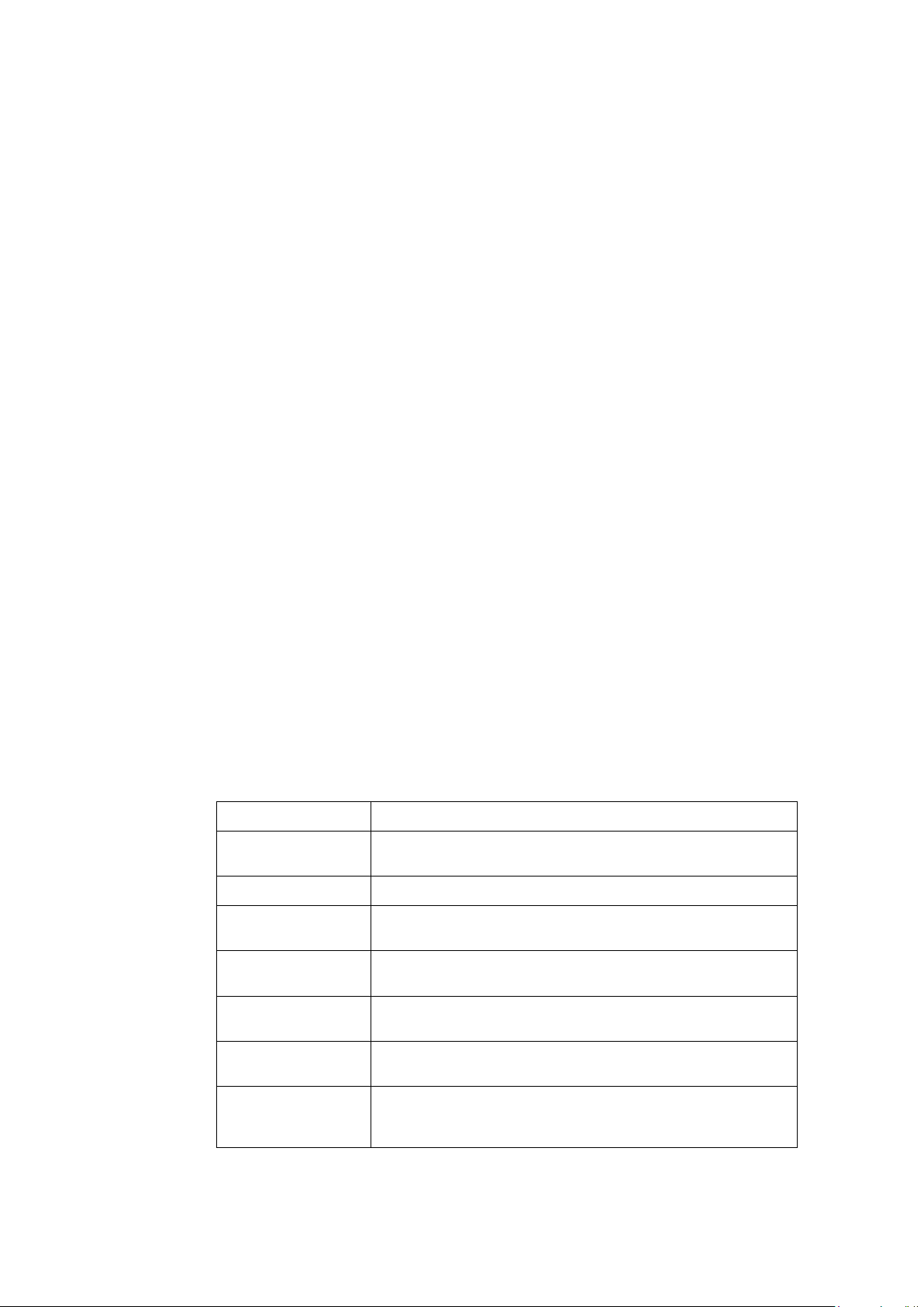
I. Command conventions
Convention Description
Boldface Bold text represents commands and keywords that you enter
literally as shown.
Italic Italic text represents arguments that you replace with actual values.
[ ] Square brackets enclose syntax choices (keywords or arguments)
that are optional.
{ x | y | ... } Braces enclose a set of required syntax choices separated by
vertical bars, from which you select one.
[ x | y | ... ] Square brackets enclose a set of optional syntax choices
separated by vertical bars, from which you select one or none.
{ x | y | ... } * Asterisk marked braces enclose a set of required syntax choices
separated by vertical bars, from which you select at least one.
[ x | y | ... ] *
Asterisk marked square brackets enclose optional syntax choices
separated by vertical bars, from which you select one choice,
multiple choices, or none.

Convention Description
&<1-n> The argument or keyword and argument combination before the
ampersand (&) sign can be entered 1 to n times.
# A line that starts with a pound (#) sign is comments.
II. GUI conventions
Convention Description
< > Button names are inside angle brackets. For example, click
<OK>.
[ ]
Window names, menu items, data table and field names are
inside square brackets. For example, pop up the [New User]
window.
/ Multi-level menus are separated by forward slashes. For
example, [File/Create/Folder].
III. Keyboard Operations
Convention Description
<KEY> Push the KEY of keyboard. For example, <Enter> is push the
Enter key.
<KEY1 + KEY2> Push some KEYs of keyboard. For example, <Ctrl+Alt+A> is
push the Ctrl key, the Alt key and the A key at the same time.
<KEY1, KEY2> Push in turn some KEYs of keyboard. For example, <Alt,A> is
push the Alt key then push the A key.
IV. Mouse Operations
Convention Description
Click Push the button of the mouse one time quickly. Usually, push the
left button.
Double Click Push the left button of the mouse two times quickly.
Drag Move the mouse while holding down the left button of the mouse.
V. Symbols
Convention Description
WARNING An alert that calls attention to important information that if not
understood or followed can result in personal injury.
CAUTION
An alert that calls attention to important information that if not
understood or followed can result in data loss, data corruption, or
damage to hardware or software.
IMPORTANT An alert that calls attention to essential information.
NOTE An alert that contains additional or supplementary information.
TIP An alert that provides helpful information.

VI. Configuration Example
The configuration example of this document is an example. Interface Number or the
information of the display command, etc. may differ from your device.

This installation guide includes 11 sections.
01 - Product overview
02 - Preparing for installation
03 - Installing the switch
04 - Accessing the switch for the first time
05 - Setting up an IRF fabric
06 - Upgrading software
07 - Maintenance and troubleshooting
08 - Appendix A Technical specifications
09 - Appendix B FRUs and compatibility matrixes
10 - Appendix C Ports and LEDs
11 - Appendix D Cooling system

Installation Guide
QX-S6600 Series Ethernet Switches
Contents
i
Contents
1 Product overview........................................................................................................................ 1-1
QX-S6648XP-6Q panel views ........................................................................................... 1-1
QX-S6648XT-6Q panel views............................................................................................ 1-3
QX-S6632QP panel views ................................................................................................. 1-5

Installation Guide
QX-S6600 Series Ethernet Switches
1 Product overview
1-1
1 Product overview
The installing direction of QSFP+ module is different depending on device.
About QX-S6648XT-6Q switch and QX-S6632QP switch, the installing direction of QSFP+
module is same as the upper and lower ports.
About QX-S6648XP-6Q switch, the installing direction of QSFP+ module is different
between the upper and lower ports.
QX-S6648XP-6Q panel views
QX-S6648XP-6Q front panel
(1) SFP+ port LED
(2) SFP+ port
(3) QSFP+ port LED
(4) QSFP+ port
QX-S6648XP-6Q rear panel
(1) System status LED (Power)
(2) Management Ethernet RJ-45 port

Installation Guide
QX-S6600 Series Ethernet Switches
1 Product overview
1-2
(3) LED for the management Ethernet RJ-45 port (LINK/ACT)
(4) LED for the management Ethernet SFP port (LINK/ACT)
(5) Fan tray slot 1
(6) Fan tray slot 2
(7) Fan tray slot 3
(8) Power module slot 1
(9) Power module slot 2
(10) Management Ethernet SFP port
(11) Console port
(12) USB mini console port
(13) USB port
The QX-S6648XP-6Q switch comes with the power module slots empty and the filler
modules for the slots as accessories. You can install one or two power modules for the
switch as needed. In Figure 1-2, two PSR450-12A-N power modules are installed. For
more information about installing and removing the power module, see "Chapter 3
Installing/removing a power module."
The QX-S6648XP-6Q switch also comes with the fan tray slots empty. You must install
three fan trays for the QX-S6648XP-6Q for adequate heat dissipation, and their models
must be the same. In Figure 1-2, three LSPM5FANSA fan trays are installed. For more
information about installing and removing the fan tray, see " Chapter 3 Installing/removing a
fan tray".
QX-S6648XP-6Q side panel
(1) Primary grounding point
(2) Auxiliary grounding point 1

Installation Guide
QX-S6600 Series Ethernet Switches
1 Product overview
1-3
QX-S6648XT-6Q panel views
QX-S6648XT-6Q front panel
(1) 1/10GBASE-T autosensing Ethernet port
(2) 1/10GBASE-T autosensing Ethernet port LED
(3) QSFP+ port
(4) QSFP+ port LED
QX-S6648XT-6Q rear panel
(1) Management Ethernet SFP port
(2) Console port
(3) USB mini console port
(4) USB port
(5) Fan tray slot 1
(6) Fan tray slot 2
(7) Fan tray slot 3
(8) Fan tray slot 4
(9) Fan tray slot 5
(10) Power module slot 1
(11) Power module slot 2
(12) System status LED (Power)
(13) LED for the management Ethernet RJ-45 port (LINK/ACT)
(14) Management Ethernet RJ-45 port
(15) LED for the management Ethernet SFP port (LINK/ACT)
The QX-S6648XT-6Q switch comes with the power module slots empty and the filler
modules for the slots as accessories. You can install one or two power modules for the
switch as needed. In Figure 1-5, two PSR450-12A-N power modules are installed. For

Installation Guide
QX-S6600 Series Ethernet Switches
1 Product overview
1-4
more information about installing and removing the power module, see "Chapter 3
Installing/removing a power module."
The QX-S6648XT-6Q switch also comes with the fan tray slots empty. You must install five
fan trays for the QX-S6648XT-6Q for adequate heat dissipation, and their models must be
the same. In Figure 1-5, five LSPM5FANSB fan trays are installed. For more information
about installing and removing the fan tray, see " Chapter 3 Installing/removing a fan tray".
QX-S6648XT-6Q side panel
(1) Primary grounding point
(2) Auxiliary grounding point 1

Installation Guide
QX-S6600 Series Ethernet Switches
1 Product overview
1-5
QX-S6632QP panel views
QX-S6632QP front panel
(1) QSFP+ port
(2) QSFP+ port LED
(3) System status LED (Power)
QX-S6632QP rear panel
(1) Fan tray slot 1
(2) Fan tray slot 2
(3) Power module slot 1
(4) Power module slot 2
(5) USB port
(6) USB mini console port
(7) Console port
(8) LINK LED for the management Ethernet RJ-45 port (LINK)
(9) ACT LED for the management Ethernet port (ACT)
(10) Management Ethernet RJ-45 port
(11) Grounding screw (auxiliary grounding point 1)
The QX-S6632QP switch comes with the two power module slots empty and a filler pannel
as an accessory. You can install one or two power modules for the switch as needed. In
Figure 1-8, two LSVM3AC650 power modules are installed in the power module slots. For
more information about installing and removing the power module, see "Chapter 3
Installing/removing a power module."
The QX-S6632QP switch comes with the two fan tray slots empty. You must install two fan
trays of the same model for the switch. In Figure 1-8, two LSWM3HFANSCB fan trays are

Installation Guide
QX-S6600 Series Ethernet Switches
1 Product overview
1-6
installed in the fan tray slots. For more information about installing and removing the fan
tray, see " Chapter 3 Installing/removing a fan tray".
QX-S6632QP side panel
(1) Primary grounding point
(2) Auxiliary grounding point 1

Installation Guide
QX-S6600 Series Ethernet Switches
Contents
i
Contents
2 Preparing for installation........................................................................................................... 2-1
Safety recommendations ................................................................................................... 2-1
Connecting the RJ45 connector ........................................................................................ 2-2
Examining the installation site ........................................................................................... 2-2
Temperature/humidity ........................................................................................................ 2-3
Cleanness .......................................................................................................................... 2-3
EMI..................................................................................................................................... 2-4
Laser safety ....................................................................................................................... 2-4
Installation tools ................................................................................................................. 2-5

Installation Guide
QX-S6600 Series Ethernet Switches
2 Preparing for installation
2-1
2 Preparing for installation
Safety recommendations
To avoid any equipment damage or bodily injury caused by improper use, read the
following safety recommendations before installation. Note that the recommendations do
not cover every possible hazardous condition.
Regarding with installation and maintenance of this product, please make the engineer who
acquired a right operating method to do that.
Remove dust on and around the Switch regularly.
Before cleaning the switch, unplug all power cords from the switch. Do not clean the
switch with wet cloth or liquid.
Before moving the Switch, unplug all power cords from the switch.
Do not place the switch near water or in a damp environment. Prevent water or
moisture from entering the switch chassis.
Do not place the switch on an unstable case or desk. The switch might be severely
damaged in case of a fall.
Ensure proper ventilation of the equipment room and keep the air inlet and outlet vents
of the switch free of obstruction.
Connect the yellow-green protection grounding cable before power-on.
Make sure the operating voltage is in the required range.
Please don't open equipment. Breakdowns when opening, will be applying of the
guarantee.
When replacing FRUs, including power modules and fan trays, wear an
ESD-preventive wrist strap to avoid damaging the units.
Please be sure to do service operation of the equipment which is being used after a
power supply is off.

Installation Guide
QX-S6600 Series Ethernet Switches
2 Preparing for installation
2-2
Connecting the RJ45 connector
NOTE:
When connecting the RJ45 cable, wear a wrist strap to protect against static electricity.
Do not touch the RJ45 Ethernet cable terminal. If you touch the RJ45 Ethernet cable
terminal which is connecting to the Switch, the interface circuit may be broken by the static
electricity. When you connect the Console cable, you need also a same care.
Connecting the RJ45 connector
Examining the installation site
The QX-S6600 Series switches must be used indoors.
Mount your switch in a rack and make sure:
Adequate clearance is reserved at the air inlet and exhaust vents for ventilation.
The rack has a good ventilation system.
Identify the hot aisle and cold aisle at the installation site, and make sure ambient air
flows into the switch from the cold aisle and exhausts to the hot aisle.
Identify the airflow designs of neighboring devices, and prevent hot air flowing out of
the bottom device from entering the top device.
The rack is sturdy enough to support the switch and its accessories.

Installation Guide
QX-S6600 Series Ethernet Switches
2 Preparing for installation
2-3
The rack is well earthed.
To ensure normal operation and long service life of your switch, install it in an environment
that meets the requirements described in the following subsections.
Temperature/humidity
Maintain appropriate temperature and humidity in the equipment room.
Lasting high relative humidity can cause poor insulation, electricity creepage,
mechanical property change of materials, and metal corrosion.
Lasting low relative humidity can cause washer contraction and ESD and bring
problems including loose captive screws and circuit failure.
High temperature can accelerate the aging of insulation materials and significantly
lower the reliability and lifespan of the switch.
For the temperature and humidity requirements of different switch models, see "Appendix A
Technical specifications".
Cleanness
Dust buildup on the chassis may result in electrostatic adsorption, which causes poor
contact of metal components and contact points, especially when indoor relative humidity is
low. In the worst case, electrostatic adsorption can cause communication failure.
Table 2-1 Dust concentration limit in the equipment room
Substance Concentration limit (particles/m³)
Dust
≤ 3 x 10
4
(no visible dust on the tabletop over three days)
Note:
Dust diameter ≥ 5 μm
The equipment room must also meet strict limits on salts, acids, and sulfides to eliminate
corrosion and premature aging of components, as shown in Table 2-2

Installation Guide
QX-S6600 Series Ethernet Switches
2 Preparing for installation
2-4
Table 2-2 Harmful gas limits in the equipment room
Gas Maximum concentration (mg/m3)
SO2
0.2
H2S
0.006
NH3
0.05
Cl2
0.01
EMI
All electromagnetic interference (EMI) sources, from outside or inside of the switch and
application system, adversely affect the switch in a conduction pattern of capacitance
coupling, inductance coupling, electromagnetic wave radiation, or common impedance
(including the grounding system) coupling. To prevent EMI, take the following actions:
Please take the effective measures to reduce the intervention the power supply
system exerts on the switch.
Keep the switch far away from high-power radio launchers, radars, and equipment
with high frequency or high current.
If AC power is used, use a single-phase three-wire power receptacle with protection
earth (PE) to filter interference from the power grid.
Keep the switch far away from radio transmitting stations, radar stations, and
high-frequency devices.
Use electromagnetic shielding, for example, shielded interface cables, when
necessary.
Route interface cables only indoors to prevent signal ports from getting damaged by
overvoltage or overcurrent caused by lightning strikes.
Laser safety
The QX-S6600 Series switches are Class 1M laser devices.
This manual suits for next models
2
Table of contents
Other NEC Network Router manuals
Popular Network Router manuals by other brands

TRENDnet
TRENDnet TEW-731BR Quick installation guide

PROLiNK
PROLiNK Hurricane 9300G user manual

weintek
weintek MT8053iE Series Installation instruction

Linksys
Linksys BEFSX41 - Instant Broadband EtherFast Cable/DSL Firewall... user guide

H3C
H3C SR6604 installation guide

Linksys
Linksys WET11 - Instant Wireless EN Bridge Network... user guide