NEC DTE-25G5THS User manual

September, 2002
NEC Corporation
Service manual
59/68 Cm STEREO Color Television
MODEL : DTE-25G5THS
DTE-29G5TH
FS-59T90
FS-68T90
DTE-25G4ZH
DTE-29G4ZH
FS-59V81
FS-68V81
CHASSIS : CP-785A
S/M No. : TCP785AEFR1

Contents
1 - Main features
2
1-1 Specifications 2
1-2 External Terminals 2
1-3 Channel table 4
2 - Safety instruction 7
3 - Alignment instructions 8
3-1 Microcontroller configuration : Service mode 8
3-2 Microcnotroller configuration : Option 8
3-3 TV set Alignment 10
4 - IC description 12
4-1 TDA936x TV signal processor - TXT with embedded -Controller 12
4-2 MSP34 Multistandard Sound Processor 19
4-3 TDA894x J Stereo Audio Amplifier 23
4-4 TDA835x J Vertical Amplifier 24
4-5 TDA6107Q 26
4-6 24C08 8 K bit EEPROM 27
4-7 STR-F665X 28
5 - Circuit description 30
5-1 Block diagram 30
5-2 IF 34
5-3 Source switching 35
5-4 -Controller I/O pin configuration and function 35
5-5 Sound processing 36
5-6 Sound amplification 37
5-7 Vertical deflection 38
5-8 Power supply (STR-F6654) 39
5-9 TV start-up, TV normal run and stand by mode operations 43
6 - Service parts list 50
6-1 PCB Difference Part (PCB change of FS-xxT90) 51
6-2 CRT Difference Part 59
6-3 Function & Cabinet Difference Part 60
6-4 All Electrical Parts List 61
7 - Compaitible Components List for FS-xxT90, xxV81
8 - Exploded view 83
9 - PCB Layout 84
9-1 Old Main PCB (4859804393) 85
9-2 New Main PCB (4859806493) 86
9-3 Control PCB (4859833214) 87
10 - Circuit Diagram 88
10-1 Old Main PCB 88
10-2 New Main PCB & Control PCB 89
-1--1-

-2-
Service Manual CP-785A
1-1 Specifications
1-2 External Teminals
1-2-1 Input 2 : Rear RCA
TV standard PAL, - B/G, H
Sound system NICAM B/G
FM 2Carrier B/G
Power consumption 25” : 113W approx.
29” : 118W approx.
Sound Output Power 25” : 5W x 5W (at 60% mod, 10% THD)
29” : 5W x 5W (at 60% mod, 10% THD)
Speaker 25” : 7W 8 ohm x 2
29” : 7W 8 ohm x 2
Teletext system 10 pages memory FASTEXT (FLOF or TOP) : Option
Aerial input 75 ohm unbalanced
Channel coverage Off-air channels, S-cable channels and hyperband
Tuning system frequency synthesiser tuning system
Visual screen size 25” : 59 Cm
29” : 68 Cm
Channel indicatio On Screen Display
Program Selection 100 programmes
Aux. terminal INPUT1(SCART or RCA)
- SCART : Audio / Video In, S-VHS In(with cable)
- RCA : Audio / Video In. (SVHS : disable)
INPUT2(RCA) : Audio / Video In
OUTPUT(RCA) : TV OUT
Headphone jack (3.5 mm) on front of cabinet
Remote Control Unit R-44N08(RD-D90) for with Teletext
R-44N09(RD-085) for with Teletext
Pin Signal Matching value
1(Yellow) Video Input 1.0 Vpp+/- 3dB, Impedance 75 ohm
2(White) Audio Input Left 0.5 Vrms, Impedance > 10k ohm
3(Red) Audio Input Right 0.5 Vrms, Impedance > 10k ohm
1-2-2 Output : Rear RCA
Pin Signal Matching value
1(Yellow) TV Video 1.0 Vpp+/- 3dB, Impedance 75 ohm
2(White) TV Audio Left 0.5 Vrms at RF Sound FM 54%Mod.(27kHz dev.)
3(Red) TV Audio Right 0.5 Vrms at RF Sound FM 54%Mod.(27kHz dev.)
1-2-3 Input1 : Rear RCA or Scart
-RCA Jack : Input1 (S-VHS not available)
Pin Signal Matching value
1(Yellow) Video Input 1.0 Vpp+/- 3dB, Impedance 75 ohm
2(White) Audio Input Left 0.5 Vrms, Impedance > 10k ohm
3(Red) Audio Input Right 0.5 Vrms, Impedance > 10k ohm
-2-

-3-
Service Manual CP-785A
- SCART (21pin Euro Scart) : Input1 & S-VHS input
Pin Signal Matching value
1 N.C.
2 Audio Input Right 0.5 Vrms, Impedance > 10 kΩ
3 N.C.
4 Audio Earth
5 Earth
6 Audio Input Left 0.5 Vrms, Impedance > 10 kΩ
7 N.C.
8 N.C.
9 N.C.
10 N.C.
11 N.C.
12 N.C.
13 N.C.
14 Earth
15 Chroma Input +/- 3dB for a luminance signal of 1 Vpp
16 N.C.
17 Earth
18 Video In Earth
19 N.C.
20 Video Input / Y Input 1 Vpp +/- 3dB, Impedance 75 ohm
21 Common Earth

-4-
Service Manual CP-785A
1-3 Channel table
FREQUENCY TABLE CP-785A
CH AUSTRALIA N/Z˅land
C00 46.25
C01 57.25
C02 64.25
C03 86.25
C04 95.25
C05 102.25
C5A 138.25
C06 175.25
C07 182.25
C08 189.25
C09 196.25
C10 209.25
C11 216.75
N01 - 45.25
N02 - 55.25
N03 - 62.25
N08 - 203.25
N09 - 210.25
N10 - 217.25
- - -
C21 471.25
C22 479.25
C23 487.25
C24 495.25
C25 503.25
C26 511.25
C27 519.25
C28 527.25
C29 534.25
C30 541.25
C31 548.25
C32 555.25
C33 562.25
C34 569.25
C35 576.25
C36 583.25
C37 590.25
C38 597.25
C39 603.25
C40 610.25
C41 617.25
C42 624.25

-5-
Service Manual CP-785A
CH AUSTRALIA N/Z˅land
C43 631.25
C44 638.25
C45 645.25
C46 652.25
C47 659.25
C48 666.25
C49 673.25
C50 680.25
C51 687.25
C52 694.25
C53 701.25
C54 708.25
C55 715.25
C56 722.25
C57 729.25
C58 736.25
C59 743.25
C60 750.25
C61 757.25
C62 764.25
C63 771.25
C64 779.25
C65 786.25
C66 793.25
C67 800.25
C68 807.25
C69 814.25
C70 -
C71 -
C72 -
C73 -
C74 -
C75 -
C76 -
C77 -
S01 105.25
S02 112.25
S03 119.25
S04 126.25
S05 133.25
S06 140.25
S07 147.25
S08 154.25
S09 161.25
S10 168.25
S11 231.25

-6-
Service Manual CP-785A
CH AUSTRALIA N/Z˅land
S12 238.25
S13 245.25
S14 252.25
S15 259.25
S16 266.25
S17 273.25
S18 280.25
S19 287.25
S20 294.25
S21 303.25
S22 311.25
S23 319.25
S24 327.25
S25 335.25
S26 343.25
S27 351.25
S28 359.25
S29 367.25
S30 375.25
S31 383.25
S32 391.25
S33 399.25
S34 407.25
S35 415.25
S36 423.25
S37 431.25
S38 439.25
S39 447.25
S40 455.25
S41 463.25

-7-
Service Manual CP-785A
2 - Safety instruction
WARNING: Only competent service personnel may carry out work involving the testing or repair of this
equipment.
X-RAY RADIATION PRECAUTION
1. Excessive high voltage can produce potentially hazardous X-RAY RADIATION. To avoid such
hazards, the high voltage must not exceed the specified limit. The nominal value of the high voltage of
this receiver is 26~28 KV (25” - 29”) at max beam current. The high voltage must not under any
circumstances, exceed 29.5 KV (25") or 31 KV (29"). Each time a receiver requires servicing, the
high voltage should be checked. It is important to use an accurate and reliable high voltage meter.
2.The only source of X-ray Radiation in this TV receiver is the picture tube. For continued X-ray
RADIATION protection, the replacement tube must be exactly the same type tube as specified in the
parts list.
SAFETY PRECAUTION
1. Potentials of high voltage are present when this receiver is operating. Operation of the receiver outside
the cabinet or with the back board removed involves a shock hazard from the receiver.
1) Servicing should not be attempted by anyone who is not thoroughly familiar with the precautions
necessary when working on high voltage equipment.
2) Discharge the high potential of the picture tube before handling the tube. The picture tube is highly
evacuated and if broken, glass fragments will be violently expelled.
2. If any Fuse in this TV receiver is blown, replace it with the FUSE specified in the Replacement Parts
List.
3. When replacing a high wattage resistor (oxide metal film resistor) in circuit board, keep the resistor 10
mm away from circuit board.
4. Keep wires away from high voltage or high temperature components.
5. This receiver must operate under AC 240 volts, 5O Hz. NEVER connect to DC supply or any other
power or frequency.
PRODUCT SAFETY NOTICE
Many electrical and mechanical parts in this equipment have special safety-related characteristics. These
characteristics are often passed unnoticed by a visual inspection and the X-ray Radiation protection
afforded by them cannot necessarily be obtained by using replacement components rated for higher
voltage, wattage, etc. Replacement parts which have these special safety characteristics are identified in
this manual and its supplements, electrical components having such features are identified by designated
symbol on the parts list. Before replacing any of these components, read the parts list in this manual
carefully. The use of substitutes replacement parts which do not have the same safety characteristics as
specified in the parts list may create X-ray Radiation.

-8-
Service Manual CP-785A
3 - Alignment instructions
3-1 Microcontroller configuration : Service mode
To switch the TV set into service mode please see instruction below.
1 - Select pr. number 91
2 - Adjust sharpness to minimum value and exit all menu.
3 - Quickly press the key sequence : RED - GREEN - menu
To exit SERVICE menu press menu key or Operate(Std By) key.
In Service Mode press “OK” to stop the microcontroller i.e. the I2C bus is free and the set can be controlled by
external equipment. Press “OK” again to allow the microcontroller to control the set again.
3-2 Microcontroller configuration : Option
Section Items BareDATA 29ˉ25ˉ21ˉREMARK
G5TH G4ZH G5THS G4ZH
AGC 32 38 38 38 38 38
BIAS R/G 31/31 31/31 31/31 31/31 31/31 31/31 old micom : 8/8
DRIVE R/G/B 32/32/32 32/32/28 32/32/28 32/32/32 32/32/32 32/32/32
H-PARALLEL 31 36 36 32 32 32
H-BOW 42 34 34 35 35 35
For H-SHIFT 25 30 30 30 30 27
Adjustment V-SLOPE 32 35 35 35 35 35
(Variable) V-Amplitude 39 19 19 30 30 27
V. S-Correction 13 27 27 25 25 23
V SHIFT 32 34 34 34 34 45
H-WIDTH 32 37 37 57 57 33
EW Parabola 32 20 20 17 17 0
Up-Conner 32 32 32 42 42 32
Dn-Conner 32 32 32 42 42 32
EW Trapezium 32 29 29 31 31 29
Option 04 04 04 04 04 04 0,1,2,3 : For D/W Remote controller
4,5,6,7 : For NEC Remote controllerˉ
CH Lock
or OFF OFF OFF OFF OFF OFF “Hotel Lock” will be changed to “CH Lock”
HOTEL Lock
HOTEL Max Vol
For or 15 43 43 43 43 43 “
Hotel Max Vol” will be changed to “Max Vol”
Function Max VOL
Change Colck Pr. 01 07 07 07 07 07 change the reference channel
(OPTION) for Automatic clock setting
SVHS ON ON OFF ON OFF OFF OFF : disable S-VHS Input
AV START OFF OFF OFF OFF OFF OFF “AV START” is add
KEY LOCK OFF OFF OFF OFF OFF OFF “KEY LOCK” is add
SCREEN 24 31 31 33 33 35 each CRT has different Adjusting point

-9-
Service Manual CP-785A
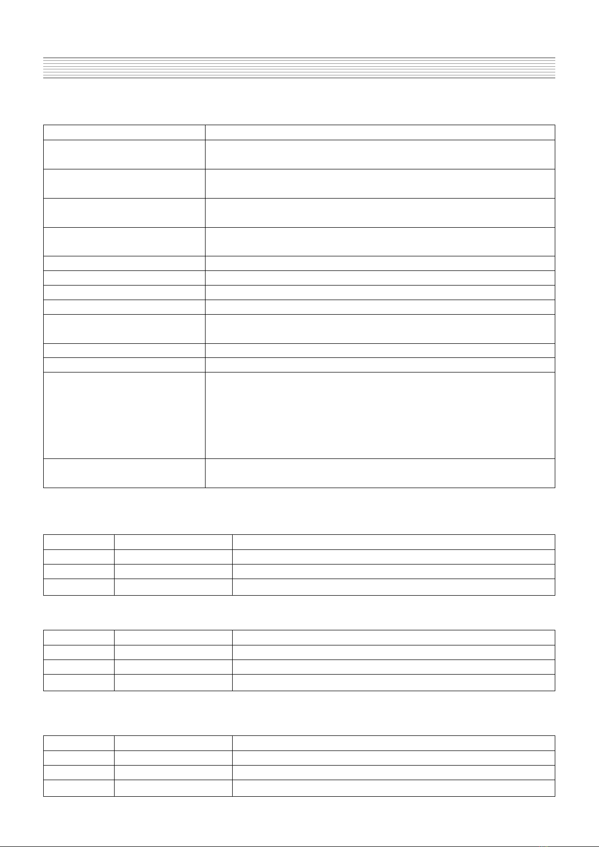
Lock Function Name Description Applied CPU Remark
Models Version
- Channel Setting : Enable / Disable
Current - Volume Limit (Hotel Max Vol) : Enable / Disable FS-59T90 These current Lock fuction
Lock - When this function is active, It is impossible to change FS-68T90 DW9365-CH1 will be change to New Lock Fuction.
Function Hotel Lock ON / OFF the channel data (can not enter the INSTALL menu) & PF51T31
the sound can be limited by
ˈHotel Max Volˉ.
- This Function is available When
ˈHotel Lockˉis on
Hotel (This function is depend on Hotel Lock Function)
Max. Volume 00 ~ 43(max.) - When Hotel Lock is off , the sound dose not limited.
- Channel Setting : Impossible / Possible - Each Lock Function is independence
CH Lock ON / OFF - The former
ˈHotel modeˉhas been removed and added
ˈCH lockˉ- It is possible to change the features by
- When this function is active, It is impossible to change combination of each function
New the channel data (can not enter the INSTALL menu) FS-59V81 - We will apply these new lock fuction to
Lock - Max Volume is limited. FS-68V81 current TEXT micom.
Function - Even if
ˈCH lockˉis not active the sound can be DW9365-CH2
Max Vol 00 ~ 43(max.) limited by the service function
ˈMax Volˉ. (FS-59T90) DW9385-CH1 - Examlpe)
- In case of virgin EEPROM, the default setting is 43 (Max). (FS-68T90) CH lock=ON, Max Vol=20
- In normal, the
ˈMax. Vol.ˉmust be 43 (PF51T31) ==> CH setting = Disable
- When
ˈVA startˉis active, the set always start in AV1 mode Volume Limit : under 20
AV Start ON / OFF (main AC switch on/off & remote controller on/off). Max. Vol=20, AV start=ON, Key Lock=ON
- In case of virgin EEPROM, the default setting is OFF. ==> Volume Limit : under 20
Key Lock ON / OFF - When active the local keyboard cannot be used. Tv is always turn on at AV1 mode
- In case of virgin EEPROM, the default setting is OFF. Front local keys are not operate
Change of Lock Function
(1) Model
- New AV Stereo Model (FS-xxV81, DTE-xxG4ZH) will be applied the new lock function from 1st MP.
- Current Model (FS-xxT90, DTE-xxG5THx) will be changed to new lock function when the CPU software is changed (TDA9365 : DW9365-CH1 ==> DW9365-CH2)
(2) Details
* Note : These Function is changed only Service Mode not Factory mode. So you must use the user˅s remote controller
- Change the PR. No. to 91 ==> change the sharpness to 00(min) in Picture control Menu ==> Exit the User control Menu ==> Press the [RED],[GREEN],[MENU] quickly
- Then the Service Menu is appeared.

-10-
Service Manual CP-785A
3-3 TV set Alignment
3-3-1 - G2 alignment
- TV in AV mode without video signal Black screen.
- TV preset with WP Red, WP Green and WP Blue equal to 32.
- TV preset with Black R, Black G equal to 32.
- Set TV in NORMAL I mode
- Adjust screen volume ( on FBT ) such that the highest cathod cut-off voltage measured on CRT
board, is V cut off 5V.
Screen size Vcut-off
25” 140V
29” 140V
3-3-2 - White balance
- Select a dark picture and adjust Black G and Black R to the desired colour temperature.
- Select a bright picture and adjust WP Red, WP Green, WP Blue to the desired colour temperature.
3-3-3 - Focus
- Adjust the Focus volume ( on FBT ) to have the best resolution on screen.
3-3-4 - Vertical geometry
- Adjust the Vertical Amplitude, Shift, S-
Correction and Slope to compensate for vertical
distortion.
3-3-5 - Horizontal picture centering
- Adjust H Shift to have the picture in the center of the screen.
3-3-6 - East / West correction
- Adjust the H Parall, H Bow, H Width, EW Parabo, Up Corner, Dw Corner, EW trapez to compensate
for geometrical distortion.
H. Parall EW.Parabola

-11-
Service Manual CP-785A
3-3-7 - AGC
- Adjust the antenna signal level at 68 dBV 2 (UHF - CH25)
- Set RF AGC to 0.
- Increase RF AGC level and stop when the level on pin 6 of TDA936x goes below 2.5 Vdc
H. Bow
H.Width
Up Corner
Dw Corner

-12-
Service Manual CP-785A
4 - IC description
4-1 TDA936x TV signal processor - Teletext decoder with embedded -Controller.
- TDA936x : TEXT Available
- TDA938x : TEXT Not Available
CHASSIS(MODELS) IC MARKING TEXT TV STANDARD Version History
CP-785A, AF TDA9365 10 PAGE TEXT TDA-9365/N1(otp)
(DTE-xxxxTHx) (DW9365/N2-CH1) (Pan-Eur opeun) PLA/SECAM TDA9365/N2-H:DW9365-CH(Masking)
(FS-XXT90,PF-51T31) TDA9365/N2-I : DW9365-CH2(Masking)
CP-785A TDA9385
(DTE-xxxxZH) -OTP : TDA9385/N2/I Not USED PAL TDA9385/N2-I : DW9385-CH1
(FS-xxV81) -Marsking : TDA9385/N2/I
DW9385/N2/-I-CH1
TV-signal Processor
Multi-standard vision IF circuit with alignment-free PLL demodulator
Internal (switchable) time-constant for the IF-AGC circuit
Source selection between 'Internal' CVBS and external CVBS or Y/C signals
Integrated chrominance trap circuit
Integrated luminance delay line with adjustable delay time
Asymmetrical ‘ delay line type’ peaking in the luminance channel
Black stretching for non-standard luminance signals
lntegrated chroma band-pass filter with switchable centre frequency
Only one reference (12 MHz) crystal required for the -Controller, Teletext and the colour decoder
PAL / NTSC or multistandard colour decoder with automatic search system
Internal base-band delay line
RGB control circuit with 'Continuous Cathode Calibration', white point and black level off set
adjustment so that the colour temperature of the dark and the bright parts of the screen can be chosen
independently.
The Text/OSD signals are internally supplied from the -Controller/Teletext decoder
Contrast reduction possibility during mixed-mode of OSD and Text signals
Horizontal synchronisation with two control loops and alignment-free horizontal oscillator
Vertical count-down circuit
Vertical driver optimised for DC-coupled vertical output stages
Horizontal and vertical geometry processing
Horizontal and vertical zoom function for 16 : 9 applications
Horizontal parallelogram and bow correction for large screen picture tubes

-13-
Service Manual CP-785A
-Controller
80C51 -controller core standard instruction set and timing
1 s machine cycle
32 - 128Kx8-bit late programmed ROM
3 - 12Kx8-bit Auxiliary RAM (shared with Display and Acquisition)
Interrupt controller for individual enable/disable with two level priority
Two 16-bit Timer/Counter registers
WatchDog timer
Auxiliary RAM page pointer
16-bit Data pointer
IDLE and Power Down (PD) mode
14 bits PWM for Voltage Synthesis Tuning
8-bit A/D converter
4 pins which can be programmed as general I/0 pin, ADC input or PWM (6-bit) output
Data Capture
Text memory 10 pages
Inventory of transmitted Teletext pages stored in the Transmitted Page Table (TPT) and Subtitle Page
Table (SPT)
Data Capture for US Closed Caption
Data Capture for 525/625 line WST, VPS (PDC system A) and Wide Screen Signalling (WSS) bit
decoding Automatic selection between 525 WST/625 WST
Automatic selection between 625 WST/VPS on line 16 of VBI
Real-time capture and decoding for WST Teletext in Hardware, to enable optimised -processor
throughput
Automatic detection of FASTEXT transmission
Real-time packet 26 engine in Hardware for processing accented, G2 and G3 characters
Signal quality detector for video and WST/VPS data types
Comprehensive teletext language coverage
Full Field and Vertical Blanking lnterval (VBI) data capture of WST data
Display
Teletext and Enhanced OSD modes
Features of lever 1.5 WST and US Close Caption
Serial and Parallel Display Attributes
Single/Double/Quadruple Width and Height for characters
Scrolling of display region
Variable flash rate controlled by software
Enhanced display features including overlining, underlining and italics
Soft colours using CLUT with 4096 colour palette
Globally selectable scan lines per row (9/10/13/16) and character matrix [12x10, 12xl3, 12x16 (VxH)]
Fringing (Shadow) selectable from N-S-E-W direction
Fringe colour selectable
Meshing of defined area

-14-
Service Manual CP-785A
Contrast reduction of defined area
Cursor
Special Graphics Characters with two planes, allowing four colours per character
32 software redefinable On-Screen display characters
4 WST Character sets (GO/G2) in single device (e.g. Latin, Cyrillic, Greek, Arabic)
G1 Mosaic graphics, Limited G3 Line drawing characters
WST Character sets and Closed Caption Character set in single device
Data Capture
The Data Capture section takes in the analogue Composite Vidéo and Blanking Signal (CVBS), and from
this extracts the required data, which is then decoded and stored in memory.
The extraction of the data is performed in the digital domain. The first stage is to convert the analogue
CVBS signal into a digital form. This is done using an ADC sampling at 12MHz. The data and clock
recovery is then performed by a Multi-Rate Video Input Processor (MuIVIP). From the recovered data
and clock the following data types are extracted WST Teletext (625/525), Closed Caption, VPS, WSS.
The extracted data is stored in either memory (DRAM) via the Memory Interface or in SFR locations.
Data Capture Features
- Video Signal Quality detector
- Data Capture for 625 line WST
- Data Capture for 525 line WST
- Data Capture for US Closed Caption
- Data Capture for VPS data (PDC system A)
- Data Capture for Wide Screen Signalling (WSS) bit decoding
- Automatic selection between 525 WST/625WST
- Automatic selection between 625WST/VPS on line 16 of VBI
- Real-time capture and decoding for WST Teletext in Hardware, to enable optimised microprocessor
throughput
- 10 pages stored On-Chip
- lnventory of transmitted Teletext pages stored in the Transmitted Page Table (TPT) and Subtitle Page
Table (SPT)
- Automatic detection of FASTEXT transmission
- Real-time packet 26 engine in Hardware for processing accented, G2 and G3 characters
- Signal quality detector for WST/VPS data types
- Comprehensive Teletext language coverage
- Full Field and Vertical Blanking Interval (VBI) data capture of WST data

-15-
Service Manual CP-785A
+8V
13
43
24
23
42
40
CVBS/Y
IFIN
TUNERAGC
SOUND
TRAP
27 37
VIDEO SWITCH
VIDEO IDENT.
VIDEO FILTERS
38 (35) (35)
(32)
28 29 44 31 60 55 59 58 57 2 3 4 9 12
10 PAGE
MEMORY
TELETEXT/OSD
DISPLAY
+3.3V
5654 61
(20)
AUDEXT
SIFIN
QSSOUT/AMOUT
AMOUT
RESET
VPE
LED OUT (2x)
VST OUT
ADC IN (4x)
I/O PORTS (4x)
1+62-64
SCL SDA
5-8
10/11
VISION IF
ALIGNMENT-FREE
PLL DEMOD.
AGC/AFC
VIDEO AMP.
CHROMA
PAL/SECAM/NTSC
DECODER
H/V SYNC SEP.
H-OSC. + PLL
(32)
30
41
18
39
14
19
17
H
34 16 33 25 26 22 21 36 (20) 46 47 48 45
50
49
53
52
51
BLKIN
BCLIN
BO
GO
RO
COR
CONTR/BRIGHTN
OSD/TEXT INSERT
CCC
WHITE-P. ADJ.
HOUT V-DRIVE EHTO EWD R/V
Y
R
R
V
H
G
G
B
BBL
RGB/YUV INSERT
RGB/YUV MATRIX
SATURATION
YUV/RGB MATRIX
U
V
G/Y B/U BL
V
V-DRIVE +
GEOMETRY
ROM/RAM CVBS
I2C-BUS
TRANSCEIVER
VST PWM-DAC
I/O PROTS
TELETEXT
ACQUISITION
SYNC
EW GEOMETRY
H-DRIVE
2nd LOOP
H-SHIFT
BASE-BAND
DELAY LINE
REF
REF
QSS SOUND IF
AGC
QSS MIXER
AM DEMODULTOR
ENIANCED
80C51 CPU
LUMA DELAY
PEAKING
BLACK STRETCH

-16-
Service Manual CP-785A
SYMBOL PIN DESCRIPTION
n.u. 1 Port 1.3 Not used.
SCL 2 I2C bus clock line
SDA 3 I2C Data line
SECAM L
˅
out 4 Port 2.0 : High when L
ㅤ
selected (PushPull )
OCP 5 Port 3.0 : Over Current Protection
RF AGC in 6 ADC 1 : For factory use only ( High impedance )
Key-in 7 ADC 2 : local key input ( High impedance )
S/SW 8 ADC 3 : Scart Slow switching input
VssC/P 9 digital ground for -controller core and peripheral
LED 1 10 port 0.5 ( 8mA current sinking capability )
LED 2 11 port 0.6 ( 8mA current sinking capability )
VSSA 12 analog ground of teletext decoder and digital ground of TV processor
SEC PLL 13 SECAM PLL decoupling
VP2 14 2nd supply voltage TV-processor
DECDIG 15 decoupling digital supply of TV-processor
PH2LF 16 phase-2 filter
PH1LF 17 phase-1 filter
GND3 18 ground 3 for TV-processor
DECBG 19 bandgap decoupling
AVL/EWD 20 East / West drive output
VDRB 21 vertical drive B output
VDRA 22 vertical drive A output
IFIN1 23 IF input 1
IFIN2 24 IF input 2
IREF 25 reference current input
VSC 26 vertical sawtooth capacitor
TUNERAGC 27 tuner AGC output
SIFIN1 28 SIF input 1
SIFIN2 29 SIF input 2
GND2 30 ground 2 for TV processor
SIF AGC 31 AGC sound IF
REF0 32 n.u.
HOUT 33 horizontal output
FBISO 34 flyback input / sandcastle output
QSS out 35 QSS intercarrier output
EHT0 36 EHT/Overvoltage protection
PLLIF 37 IF PLL loop filter
IFVO 38 IF video output
VP1 39 main supply voltage TV-processor
CVBSINT 40 internal CVBS input
GND1 41 ground 1 for TV-processor
CVBS/Y 42 external CVBS/Y input
CHROMA 43 chrominance input (SVHS)
AMOUT 44 n.u.
INSSW2 45 2nd RGB insertion input
R2IN 46 2nd R input
PINNING

-17-
Service Manual CP-785A
SYMBOL PIN DESCRIPTION
G2IN 47 2nd G input
B2IN 48 2nd B input
BCLIN 49 beam current limiter input
BLKIN 50 black current input
R0 51 RED Output
G0 52 GREEN Output
B0 53 BLUE Output
VDDA 54
analog supply of Teletext decoder and digital supply of TV-Processor (3.3V)
VPE 55 OTP programming supply
VDDC 56 digital supply to core (3.3V)
OSCGND 57 oscillator ground supply
XTALIN 58 crystal oscillator input
XTALOUT 59 crystal oscillator output
RESET 60 reset
VDDP 61 digital supply to periphery (3.3V)
Audio Mute 62 Port 1.0 : Audio mute output (PushPull )
Power 63 Port 1.1 : Power output (PushPull )
IR in 64 Interrupt input 0 : R/C Infrared input

-18-
Service Manual CP-785A
P1.3/T1
P1.6/SCL
P1.7/SDA
P2.0/TPMW
P3.0/ADC0
P3.1/ADC1
P3.2/ADC2
P3.3/ADC3
VSSC/P
P0.5
P0.6
VSSA
SECPLL
VP2
DECDIG
PH2LF
PH1LF
GND3
DECBG
AVL/EWD
VERB
VERA
IFIN1
IFIN2
IREF
VSC
TUNERAGC
AUDEEM/SIFIN1
DECSDEM/SIFIN2
GND2
SNDPLL/SIFAGC
AVL/REFO/AMOUT
P1.2/INT0
P1.1/T0
P1.0/INT1
VDDP
RESET
XTALOUT
XTALIN
OSCGND
VDDC
VPE
VDDA
BO
GO
RO
BLKIN
BCLIN
B2/UIN
G2/YIN
R2/VIN
INSSW2
AUDOUT/AMOUT
CHROMA
CVBS/Y
GND1
CVBSINT
VP1
IFVO/SVO
PLLIF
EHTO
AUDEXT/QSSO/AMOUT
FBISO
HOUT
1
2
3
4
5
6
7
8
9
10
11
12
13
14
15
16
17
18
19
20
21
22
23
24
25
26
27
28
29
30
31
32
64
63
62
61
60
59
58
57
56
55
54
53
52
51
50
49
48
47
46
45
44
43
42
41
40
39
38
37
36
35
.34
33
MXXxxx
TDA935X/6X/8X

-19-
Service Manual CP-785A
4-2 MSP34xxx Multistandard Sound Processor
The MSP34xxx is designed as a single-chip Multistandard Sound Processor for applications in
analogue and digital TV sets, video recorders, and PC cards.
MSP 3415D features
- sound IF input
- No external filters required
- Stereo baseband input via integrated AD converters
- Two pairs of DA converters
- Two carrier FM or NICAM processing
- AVC : Automatic Volume Correction
- Bass, treble, volume processing
- Full SCART in/out matrix without restrictions
- Improved FM-identification
- Demodulator short programming
- Autodetection for terrestrial TV - sound standards
- Precise bit-error rate indication
- Automatic switching from NICAM to FM/AM or vice versa
- Improved NICAM synchronisation algorithm
- Improved carrier mute algorithm
- Improved AM-demodulation
- Reduction of necessary controlling
- Less external components
Basic Features of the MSP 3415D
Demodulator and NICAM Decoder Section
The MSP 3415D is designed to simultaneously perform digital demodulation and decoding of NICAM-
coded TV stereo sound, as well as demodulation of FM or AM mono TV sound. Alternatively, two
carrier FM systems according to the German terrestrial specs can be processed with the MSP 3415D.
The MSP 3415D facilitates profitable multistandard capability, offering the following advantages:
- Automatic Gain Control (AGC) for analogue input: input range: 0.10 - 3 Vpp
- integrated A/D converter for sound-IF input
- all demodulation and filtering is performed on chip and is individually programmable
- easy realisation of all digital NICAM standards (B/G, I, L and D/K)
- FM-demodulation of all terrestrial standards (include identification decoding)
- no external filter hardware is required
- only one crystal clock (18.432 MHz) is necessary
- high deviation FM-mono mode (max. deviation: approx. ±360 kHz)
CP-785A = DTE-25G5THS(FS-59T90)
MSP34xxx MSP3410D, 3415D, 3410G, 3415G Stereo(Nicam& 2-Carrier) DTE-29G5TH(FS-68T90)
CP-785AF=DTE-21U6TH(PF-51T31)
MSP3465G - Mono(Only AV Stereo) CP-785A=DTE-25G4ZH(FS-59V81)
DTE-29G4ZH(FS-68V81)
This manual suits for next models
7
Table of contents
Other NEC TV manuals

NEC
NEC PX-42VR5W User manual

NEC
NEC PV32-AVT User manual

NEC
NEC AccuSync LCD22WMGX, AccuSync LCD24WMCX User manual

NEC
NEC PF-68T31 User manual

NEC
NEC NLT-40HDEM2 User manual

NEC
NEC PF51T31 User manual

NEC
NEC MultiSync LCD4020 User manual

NEC
NEC DTA-14V4THS User manual

NEC
NEC FS-5170 User manual

NEC
NEC E553 Parts list manual