Neco STIR-RITE III Owner's manual

STIR-RITE III
Grain Stirring Machine
Owner’s & Operator’s Manual
Effective Date:
June 5, 2104
Publication Number:
039463
Rev:
C

2
Nebraska Engineering Company (NECO) Overview ---
Since 1959, NECO equipment has been proudly designed, manufactured, and supported for
customers here in the USA and around the world. With proper operation and maintenance,
the equipment will provide years of safe and dependable service. NECO is continually testing
and improving our products in order to provide you with the safest, most ef cient, and most
economical grain handling & grain conditioning equipment available. We welcome your questions
or comments and look forward to a continued relationship, ultimately saving you valuable time and
reducing your workload.
About this manual ---
• This manual is provided to help ensure the safety of the equipment
operator, as well as others who come into contact with the equipment.
• Keep a copy of this manual in a safe place for future reference.
• Failure to read, understand, and follow the instructions within
this manual constitute a misuse of the equipment and can affect
personnel safety and the product warranty.
• Additional copies can be viewed or printed from the NECO
website www.necousa.com or contact your local dealer for
assistance.
• Language translations of this manual are made as accurately as
possible. If translation differences do occur, the English text will
prevail.
READ
and
UNDERSTAND
Watch for this symbol - it means DANGER or CAUTION !!
Be alert to the possibility of serious injury or death.
• This symbol is used to call your attention to
instructions concerning personal safety.
• It is your responsibility as an owner, operator,
or supervisor to know what hazards exist and
to make this information known to all persons
working with the equipment or who are in the
area.
Become Alert !!
Product Changes & Improvements ---
• NECO reserves the right to make changes or improvements to its products
without incurring any obligation with respect to previously manufactured products.

3
***** LIMITED WARRANTY *****
For a period of one(1) year after shipment of goods by the Buyer to the Buyer’s
customer, NECO will supply, free of charge, FOB per NECO’s factory located
in Omaha, Nebraska, replacement parts for any parts that NECO identifi es to be
defective due to workmanship or material.
• This limited warranty does not extend to parts that wear due to normal operation and need to be
replaced periodically.
• Goods not manufactured by NECO carry only their manufacturer’s warranty.
• This undertaking is in lieu of all other warranties, expressed or implied, including merchantability
and fi tness for a particular purpose.
• You must obtain a “Return Authority” form from NECO prior to returning any defective goods.
Those defective goods must be returned, freight-prepaid, to the NECO factory in Omaha,
Nebraska. See the back cover of this manual for complete address information.
• NECO reserves the right to make changes or improvements to products and goods without
incurring any obligation with respect to previously manufactured products.
• Failure to follow the instructions contained in this manual, as well as the existence of any of the
conditions listed below, will cause this Limited Warranty to be null and void:
1. Improper assembly.
2. Improper installation, including power and wiring.
3. Unauthorized alteration of the product or components therein.
4. Operation of the unit when repairs are needed.
5. Use of unauthorized parts.
6. Operation by children or uninstructed personnel.
7. Processing of materials that are abrasive, that do not fl ow freely,
or that are otherwise unsuited for processing in farm equipment.
8. Misuse of the equipment or any of its components.
9. Damage due to negligence, abuse, or accidents.
LIMITATION OF LIABILITY
• Buyer agrees that in no event shall NECO have liability for direct damages in excess of the
contract price of the goods for which the claim is made.
• Buyer further agrees that in no event shall NECO have liability for loss of use, loss of profi ts, or
for any indirect, incidental, or consequential damages on any claim of any kind.

4
***** LIMITED WARRANTY *****.................................................3
1. SAFETY .......................................................................6
2. WARNING LABELS.....................................................8
3. EQUIPMENT OVERVIEW.........................................12
EQUIPMENT DESCRIPTION......................................................12
ASSEMBLED LAYOUT WITHIN BIN .........................................13
STANDARD COMPONENT ID....................................................14
STALL TIMER (OPTIONAL) .......................................................15
4. ASSEMBLY & INSTALLATION.................................16
PRELIMINARY CONSIDERATIONS...........................................16
GATHER TOOLS, IDENTIFY COMPONENTS, ETC. ..............16
DETERMINE SPECIAL CLEARANCE ISSUES.......................16
TRACK INSTALLATION .............................................................18
BEAM ASSEMBLY .....................................................................20
SECURE THE MAIN BEAM .....................................................20
INSTALL TROLLEY RETURN CARRIAGE ..............................20
INSTALL DRIVE CLUSTER .....................................................21
INSTALL TROLLEY ASSEMBLY ..............................................21
INSTALL PIVOT BRACKET WELDMENT ...............................22
INSTALL PIVOT ARM ASSEMBLY..........................................22
INSTALL SUPPORT TUBE ASSEMBLY...................................23
INSTALL CORD SUPPORT ASSEMBLY .................................24
ELECTRICAL ROUTING & HOOKUP........................................25
ROUTE AND SECURE WIRING ..............................................25
INSTALL JUNCTION BOX .......................................................25
AMPERAGE REQUIREMENTS ...............................................26
SCHEMATIC - 230V / 1PH WITH NO STALL TIMER..............28
SCHEMATIC - 230V / 3PH WITH NO STALL TIMER..............29
SCHEMATIC - 460V / 3PH WITH NO STALL TIMER..............30
SCHEMATIC - TILT SWITCH ...................................................31
SCHEMATIC - 230V / 1PH & 3PH WITH STALL TIMER.........32
SCHEMATIC - 460V / 3PH WITH STALL TIMER...................33
TABLE OF CONTENTS

5
INSTALL DRIVE CABLE ............................................................34
HANGER CHANNEL ASSEMBLY..............................................35
RAISE TO FINAL POSITION ......................................................35
INSTALL AUGER ASSEMBLIES................................................38
INSTALL MAIN DISCONNECT SWITCH ...................................40
5. STARTUP & OPERATION ........................................42
EQUIPMENT STARTUP .............................................................42
FILLING.......................................................................................42
OPERATION ...............................................................................42
TILT SWITCH FUNCTION........................................................43
ADJUSTING THE TILT SWITCH..............................................43
ANTI-BACKUP SPROCKET FUNCTION.................................44
STALL TIMER (OPTIONAL) ADJUSTMENT ............................44
6. MAINTENANCE.........................................................45
OVERVIEW .................................................................................45
LUBRICATION REQUIREMENTS ..............................................45
7. APPENDIX .................................................................46
RESTARTING - STUCK AUGERS..............................................46
REPLACEMENT PARTS ............................................................48
STIR-RITE III - OVERALL ASSEMBLY ....................................48
MOTOR SPACER ASSEMBLY.................................................50
STIRRING AUGER...................................................................50
PIPE WELDMENT RETURN STIFFENER...............................51
BEAM WELDMENT..................................................................51
DRIVE CLUSTER SUB-ASSEMBLY (#039487) ......................52
DRIVE CLUSTER WITH MOTOR (#039547)...........................53
TROLLEY ASSEMBLY .............................................................54
TROLLEY BEARING / MOTOR BAG OF HARDWARE ...........55
TILT SWITCH (#039857)..........................................................56
COMMON PARTS BAG OF HARDWARE ...............................58
STALL TIMER (OPTIONAL) .....................................................59
ASSEMBLY & INSTALLATION (CONTINUED)

6
** Federal Occupational Safety & Health Standards for
Agriculture Subpart D, Section 1928.57 (a)(6).
WORK AREA SAFETY
• Work Area is dened as the area surround-
ing grain handling equipment.
• Make sure that no children or unauthorized
persons enter the work area.
• If anyone not involved in the actual opera-
tion DOES enter the work area, the operator
on duty should immediately shut down the
equipment until all unauthorized persons are
safely out of the work area.
• Prior to start-up and during operation, make
sure that the work area is clean and free of
any tools and debris. KEEP AREA CLEAN.
WEAR PERSONAL
PROTECTIVE EQUIPMENT (PPE)
• Utilize protective equipment, such as:
Hand protection, ear plugs, eye shields,
conned space equipment, and fall
protection equipment - to mention a few.
ANSI and NFPA STANDARDS
• Install all equipment in compliance
with ANSI and NFPA Standards.
OPERATOR QUALIFICATIONS
• Anyone who has not read or does not
completely understand all operating and
safety instructions contained within this
manual is not qualied to operate the
equipment.
• Only competent and experienced persons
should operate farm equipment. Anyone
operating or working around power equip-
ment must understand and meet all legal
and contractual requirements.
`
• The owner / operator must know the regula-
tions in your own area. For example, some
regulations specify that no one under the
age of 16 may operate power machinery
including farmstead equipment.
• Current OSHA regulations state in part, “At
the time of initial assignment and at least
annually thereafter, the employer shall in-
struct every employee in the safe operation
and servicing of all equipment with which
the employee is, or will be involved. **
• Know and use proper LOCK OUT / TAG
OUT procedures and know the emergency
shut-off locations of any and all utilities
connected to the equipment.
OPERATING PROCEDURES
• Safely follow all operating procedures out-
lined within this manual.
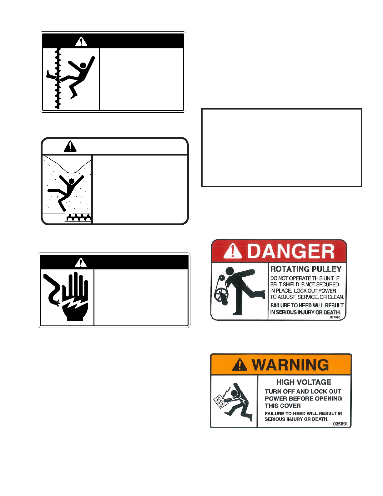
• Prior to startup, make sure that all safety
shields and warning decals are in place.
• NEVER leave equipment running without a
qualied operator present.
• Inspect the equipment periodically and be
alert for unusual noises, vibrations.
1. SAFETY
READ
and
UNDERSTAND

7
EQUIPMENT INSPECTION
• SHUT OFF, LOCK OUT, & TAG OUT all
power sources to the equipment prior
to any inspection, adjustment, service, or
maintenance.
• Inspect the equipment after assembly,
before each use, and end of season.
DRIVES AND LOCKOUTS
• Make sure the power disconnect switch can
be locked in the OFF position. This discon-
nect switch must be locked whenever work
is being performed on the equipment.
• Inspect all power drives before adding pow-
er. Chains, belts, etc. should have proper
tension or be adjusted prior to running.
• Electric motors and controls must be in-
stalled by a qualied electrician. They must
meet the standards set by the NFPA Std 70
of the National Electrical Code and all local
and state codes.
• Disconnect power before resetting motor
overloads.
BIN SAFETY
• Never enter a bin without being monitored
by another person.
• Do not enter the grain bin unless all
power to equipment has been SHUT OFF,
LOCKED OUT & TAGGED OUT.
• Use a safety harness and safety line when
inside the bin.
• Avoid walking on grain near the grain
outlets. Flowing grain can trap and
suffocate.
• Do not enter the bin if the grain has not
owed out of the bin normally. Moisture in
the bin can cause grain to form steep,
unstable inclines or bridges as shown in the
diagrams below:
Crusted Grain Forming Steep Inclines
Crusted Grain Forming a Bridge
Failure to observe these safety instructions can result in injury or death !!

8
2. WARNING LABELS
Warning Label Overview
• Occupational safety is one of NECO’s primary concerns. Warning labels that conform to
industry standards are provided to identify potential safety hazards that could cause harm and
to INCREASE YOUR AWARENESS OF THE HAZARD.
• It is the Owners & Operators responsibility to ensure that all instructions identied by warning
labels is followed - including any suggested use of personal protective equipment (PPE).
• This following warning label information identies:
1. Potential hazards that are identied by a warning label.
2. Warning label header or identication.
3. The NECO part number for that warning label.
4. The location of that warning label.
5. What that warning label looks like - note that label pictorials are not shown full size.
• If the warning labels are missing or become unreadable in any way, use the following
information to determine the required part number and contact NECO Customer Service at
402-453-6912 or toll free at 800-367-6208. They will be sent to you FREE OF CHARGE.
• Surfaces must be free of oils, dirt and moisture before applying replacement warning labels.
Table 2 - WARNING LABEL DATA
WARNING LABELS TO BE PLACED ON BIN
LABEL
ID WARNING LABEL HEADER
NECO
PART
#
QTY LOCATION
ADanger—Rotating Augers 1002306 2 See Figure 2A, page 10
B Danger—Flowing grain traps and suffocates 1002308 2 See Figure 2A, page 10
C Danger—Electrocution Hazard 1002309 2 See Figure 2A, page 10
WARNING LABELS TO BE PLACED ON EQUIPMENT
D Attention—Restarting machine after sitting idle 035692 1 See Figure 2B, page 11
E Danger—Rotating Pulley 035690 AS
REQD See Figure 2B, page 11
F Warning—High Voltage 035691 2 See Figure 2B, page 11

9
1002306
ROTATING AUGERS
NEVER ENTER THIS BIN UNTIL THE
ELECTRICAL POWER HAS BEEN
TURNED OFF AND LOCKED OUT
.
FAILURE TO HEED WILL
RESULT IN SERIOUS INJURY
OR DEATH!
DANGER
NEVER ENTER THIS BIN UNLESS
MONITORED BY ANOTHER PERSON.
.
Label ID - A. Danger—Rotating Augers
Label ID - C. Danger—Electrocution Hazard
1002309
ELECTROCUTION HAZARD
THE STIRRING MACHINE INSIDE THIS BIN IS
ELECTRICALLY POWERED.
.
NEVER ENTER THIS BIN UNTIL THE ELECTRICAL
POWER HAS BEENTURNED OFF AND LOCKED OUT.
.
NEVER ENTER THIS BIN UNLESS MONITORED BY
ANOTHER PERSON.
.
THIS MACHINE MUST BE GROUNDED.
.
FAILURE TO HEED WILL RESULT IN
SERIOUS INJURY OR DEATH!
DANGER
Label ID - D. Attention—If this machine is started
after sitting idle...
ATTENTION
If this machine is started after sitting idle it may be necessary
to turn each auger with a pipe wrench (clockwise) to free it.
WARNING: This procedure must be done with the power
disconnected.
Do not turn augers backwards or counterclockwise. This will
cause the drive wheel to lift off the track and alllow the ma-
chine to fall.
In severe cases, it is necessary to put support blocks under
the beam to prevent track or bin damage.
Nebraska Engineering Company P.N. 035692
Label ID - B. Danger—Flowing Grain
FLOWING GRAIN TRAPS & SUFFOCATES!
BRIDGED GRAIN WILL COLLAPSE & TRAP!
•Never enter this bin unless monitoried by
another person
•Shut off and lock out all power before
entering a grain bin.
•Use a safety harness & safety line in the bin.
•Avoid walking on areas of grain in the area
around the outlets
•Break up bridged grain or crusted grain with
a pole before entering the bin.
FAILURE TO HEAD CAN RESULT IN SERI-
OUS INJURY OR DEATH!
DANGER
1002308
Label ID - E. Danger—Rotating Pulley
Label ID - F. Warning—High Voltage

10
Figure 2A - Apply Bin Warning Labels
BDanger—Flowing Grain
ADanger—Rotating Augers
CDanger—Electrocution Hazard
Apply Labels to the Bin Wall at
eye level. Place them on the
same side as the door latch. Apply the “Danger—Rotating Augers,” “Danger—Flow-
ing Grain,” and “Danger—Electrocution” labels:
•on the man hatch door, and
•on the bin wall beside the bin door, latch side (at eye
level)
Labels Applied to
Man Hatch Door:
BDanger—Flowing Grain
ADanger—Rotating Augers
CDanger—Electrocution Hazard
Labels Applied
Outside Bin Door:
Apply Bin Warning Labels
Refer to Table 2 & Figure 2A:
• Two sets of Warning Labels (A, B, & C) are provided for placement on the bin.
• Make sure the surface is free of oils, dirt and moisture.
• Apply labels as shown
NOTE: If the bin has a double man-hatch door, afx the label to the inside of the outer door or to
the outside of the inner door.

11
Apply Equipment Warning Labels
Refer to Table 2 & Figure 2B:
• Warning Labels D, E, F, G, & H are applied at the factory.
• Check that all labels are present and legible each season - contact your local dealer for FREE
replacements if any are missing or damaged.
• Make sure the surface is free of oils, dirt and moisture if labels are replaced.
Figure 2B - Equipment Warning Labels
LABEL
“E”
LABEL
“D”
(AS SHOWN BELOW)
LABEL
“F”
(ON BOX COVERS)
NEVER ENTER THIS BIN UNTIL THE
ELECTRICAL POWER HAS BEEN
TURNED OFF AND LOCKED OUT.
NEVER ENTER THIS BIN UNLESS
MONITORED BY ANOTHER PERSON
ROTATING AUGERS
FAILURE TO HEED WILL
RESULT IN SERIOUS
INJURY OR DEATH!
DANGER
LABEL
“E”
(ON TROLLEY BRKT’S)

12
3. EQUIPMENT OVERVIEW
EQUIPMENT DESCRIPTION
The NECO supplied STIR-RITE III system is a simple, rugged, and reliable grain stirring machine.
Some of the included features are:
• Gooseneck Pivot Design - permits auger travel from the center of bin to within 7” of bin wall.
• Heavy Duty Backbone - the auger trolleys (2,3, or 4) are secured to the wide-ange beam,
specically chosen for its high strength and rigidity in relation to weight.
• Heavy Duty Cable - the cable propels the trolleys in a super efcient spiral stirring pattern.
• Hard Surfaced Down Augers - provides longer life under the harshest of conditions.
• Variable and Increasing Auger Pitch - easier starts and loosens / mixes the grain more uniformly.
• Proven Tilt Switch - replaces unreliable mercury switches.
• Anti-Backup Sprocket Function - keeps the unit traveling in the intended direction.
• OPTIONAL Stall Timer System - designed to protect your grain by shutting off the Stir-Rite III
movement if the unit is not advancing around the bin normally.
NOTES
• Because the Stir-Rite auger runs close to the bin wall, no inside wall ladder can be used. A
portable ladder is advised and can be obtained from your dealer.
• Reinforcements for the roof or roof ladder which may interfere with the movement of the Stir-Rite
III should be trimmed, if this cannot be done, the distance of the 10 1/4” from the eave to the track
bolt center line must be increased proportionately.
• If this is a turnkey installation and not added at a later date, assemble the top ring of the bin wall
in the usual manner and install the track sections (after the roof has been attached, the hanger
chains and brackets could be installed and raised with the bin - See “Bracket Installation”.
• Make sure there are enough roof openings to let the air ow freely and to let moisture escape.
Too few openings will render the fan system inefcient and will cause extra condensation to
form on the inside roof panels. NOTE: A bin roof can fail if fans are running without adequate
roof openings to ventilate the exhuast. See the warning below.
IMPORTANT
INSUFFICIENT AIR EXHAUST AREA MAY RESULT IN DAMAGE TO YOUR BIN
• Proper aeration or drying exhaust air openings must be provided in the form of roof vents
or open manholes when the bin fan is operating!
• A suggested minimum of 1 square foot [.09 square meters] opening for EACH 1,000 cubic
feeet per minute [30 cubic meters per minute] of air
• Before running the equipment, the operator must be sure that these openings are not
constricted by chaff, ice, or other materials during fan operation.

13
FIGURE 3A - ASSEMBLED LAYOUT WITHIN BIN
ASSEMBLED LAYOUT WITHIN BIN
Dimension “X” Must be a Mini-
mum of 10 1/4” (260.5 mm)
“X”
Center
of Track
Eave
Eave
Height
“Y”
“Y” = 3” for Bins Up to 30’
“Y” = 4” for Bins 36’ and Over
Bottom of Augers
Concrete Pad
Drying Floor
Height
Top of
Drying Floor
Space Below this Line Must be Unobstructed
Eave
Maximum Fill Height
22”
(560 mm)
The Height of the Beam at the Center of the Bin
Needs to be Higher than the
Height of the Beam at the Bin Wall*
*To Determine How Much Higher the Beam Needs to be at the Center
of the Bin than at the Bin Wall, Use the Following:
Proper Adjustment is 1/8” per foot of Beam Length
Example:
a beam for a 24’ bin is 13’ long, therefore it
would be 1 5/8” higher at the center than at the
bin wall.

STANDARD COMPONENT ID
FIGURE 3B - COMPONENT IDENTIFICATION
MAIN
BEAM
SUPPORT
TUBE
ASSEMBLY
HANGER
CHANNEL
ASSEMBLY
GOOSENECK
PIVOT FRAME
DOWN
AUGER
ASSEMBLY
TROLLEY
DRIVE
CABLE
ROTATING
CONTACTOR
TROLLEY
RETURN
CARRIAGE
TROLLEY SYSTEM
TWO, THREE, OR FOUR
DOWN AUGERS
TRACK
SYSTEM
BELT
SHIELD
PIVOT
BRACKET
WELDMENT
SAFETY
TAB (2X)
MAIN DISCONNECT
MOUNT PLATE
DRIVE
CLUSTER
TILT
SWITCH
14

15
STALL TIMER (OPTIONAL)
• The Stall Timer is designed to protect your grain by shutting off the Stir-Rite III if the unit is not
advancing around the bin normally.
• A micro-switch actuator is mounted to the upper pivot arm frame - on the underside where the
rotating contactor housing attaches. The switch either actuates or releases based on the switch
roller position in relation to the “peaks & valleys” of the cog.
• The cog rotates in conjunction with the rotating contactor as the main beam advances around
the bin..
• When the roller reaches a “peak”, it actuates the switch sending a pulse to the timer. When the
roller reaches a “valley”
• If the unit does not advance forward enough to actuate the switch in 45 minutes, the timer will
run out and the power to the Stir-Rite III will shut off.
• See ROUTE ELECTRICAL WIRING section for wiring requirements.
• See OPERATION section for adjustment procedure.
MICRO-SWITCH ACTUATOR IS
MOUNTED BENEATH CHANNEL
MICRO-SWITCH
WITH ROLLER
ROTATING CONTACTOR
HOUSING ATTACHES HERE

16
PRELIMINARY CONSIDERATIONS
4. ASSEMBLY & INSTALLATION
GATHER TOOLS, IDENTIFY COMPONENTS, ETC.
Before bin assembly, do the following:
• Gather, identify, and sort the Stir-Rite III parts in the center of the concrete pad for ease of
accessibility.
• Locate a pair of sawhorses or similar supports to assemble the beam section on.
• The track is normally positioned 10 1/4” (260 mm) down from the eave of the bin (top of the
top bin sheet) to the center line of the track. Bin roof proles and / or additional equipment,
such as spreader units, may require different positioning.
• Steeply pitched or domed roofs may allow the 10 1/4” distance to be reduced, while bins with
low or at proles may require additional clearance.
• Reinforcements for the roof or roof ladder which may interfere with the movement of the Stir-Rite
III should be trimmed, if this cannot be done, the distance of the 10 1/4” from the eave to the
track bolt center line must be increased proportionately.
• Because the Stir-Rite III auger system runs close to the bin wall, no inside wall ladder can be
used. A portable ladder is advised and can be obtained from your dealer.
DETERMINE SPECIAL CLEARANCE ISSUES
The following circumstances require checking for special clearance issues:
1. Bins less than 21’ diameter or bins with low pitch roofs.
2. Bins that have a spreader installed or plans to install a spreader in the future.
DETERMINE SMALL BIN CLEARANCE - BINS LESS THAN 21’ DIAMETER
POSITION HANGER CHANNEL WITH MINIMAL
CLEARANCE AGAINST ROOF AND VERIFY 49” DIM
TO TRACK C/L WILL ALLOW THE REQUIRED MINI-
MUM DISTANCE. Also, refer back to Figure 3A
and note the required “1/8” per foot beam rise
toward bin center” that is recommended.

17
Step 1. Obtain a measurment from the top of
peak ring to the BOTTOM MOST POSSIBLE
EXTENSION OF THE SPREADER DESIGN.
NOTE: Various spreader designs may have
pans that can hinge lower, etc. Make sure to
allow for enough clearance for total spreader
adjustment area.
Step 2. Take the actual spreader clearance
value and add 3 to 4 inches of safety clearance
and then add the 49 inch reference value.
Mark this level upon bin wall and verify that the
mark is a MINIMUM if 10 1/4 inches below the
eave level or the top of the bin wall. Increase the
10 1/4 inch clearance if needed.
DETERMINE SPREADER CLEARANCE
FINAL VERIFICATION: Double-check with positioning an actual track section with bracket. If ev-
erything is correct, procede with “TRACK INSTALLATION”. Also, refer back to Figure 3A and note
the required “1/8” per foot beam rise toward bin center” that is recommended.

18
1. Measure down from the top of the top bin sheet
the dimension necessary for special clearance
considerations (MIN 10 1/4”). Punch or drill an
11/32” (8.5 mm) diameter hole through the bin wall
at this location.
• The Stir-Rite III tracks are pre-punched with
hole spacings of 12 1/2” (317 mm) and 18 3/4”
(476 mm).
2. Insert two 5/16-18 x 3/4” grade 5 carriage bolts
into the rst and third hole at the end of the track
(See Fig. 3) and through the middle and last hole
on the splice plate. Fasten with 5/16-18” ange
nuts.
3. Insert a 5/16-18 x 3” grade 5 carriage bolt
through the second hole at the end of the track
passing through the splice plate and through a
track bracket. Insert the 3” bolt through the hole
previously drilled in the bin wall.
Refer to Figure 1 & Figure 2:
• Before installing the tracks, measure and mark
each track at the appropriate hole spacings
required for your particular application. See
Figure 1 for 1 & 2 trolley systems or see Figure
2 for 3 & 4 trolley systems.
• Begin your measurement at the second hole in
each track and mark accordingly.
Sealing Washer
and Flange Nut
Bracket
Carriage Bolts
Dimensioin
to Track C/L
Splice Plate
Flange Nut
TRACK INSTALLATION
From the outside of the bin, slide a rubber sealing
washer over the bolt and fasten using a 5/16-18
ange nut. Do Not tighten completely at this time.
Refer to Figure 3:
Figure 1 - One or Two Trolley Spacing
18.75” (476mm)
18.75” (476mm)
12.50” (317mm)
12.50” (317mm)
12.50” (317mm)
Figure 2 - Three or Four Trolley Spacing
Figure 3 - Start at Determine Track Level
Track Section

19
8. The last section of track installed will need to be
cut to length. Make sure the cut end of the track
butts against the end of the adjoining track. Drill
two 13/32” (10.5 mm) diameter holes in the cut
track, aligning the holes to be drilled, with the holes
in the splice plate [the end hole approximately 5/8”
(16 mm) from the end and then 2” (51mm) to the
next hole].
Insert a 5/16-18 x 3/4” grade 5 carriage bolt as
shown.Position a track bracket behind the splice
plate and insert a 5/16-18 x 3” grade 5 carriage
bolts through the track, the plate, the bracket and
the bin wall.
Secure using a sealing washer and a 5/16-18
ange nut (See Fig. 5).
4. Hold the track level so the next hole can be properly
punched or drilled. Install another bracket and
secure using a 3” grade 5 carriage bolt, sealing
washer and ange nut, continue to the next hole
using the same method of assembly and so on.
Leave the hardware loose enough to allow the track
to have some movement for aligning and installing
the splice ends and track brackets.
5. As you come to the end of each track section, the
track will have two holes. Position a splice plate
behind the holes, insert a 5/16-18 x 3/4” grade 5
carriage bolt as shown. Position a track bracket
behind the second hole and insert a 5/16-18 x 3”
grade 5 carriage bolt through the hole of the track,
the plate, the bracket, and the bin wall.
Secure using a sealing washer and a 5/16-18
ange nut (See Fig. 4).
6. The adjoining section of track will attach to the
splice plate using two 5/16-18 x 3/4” grade 5 car-
riage bolts and ange nuts (See Fig.4).
Position a bracket behind the splice plate and insert
a 5/16-18 x 3” grade 5 carriage bolt through the
track, the plate, the bracket and the bin wall. Se-
cure using a sealing washer and a 5/16-18 ange
nut (See Fig. 4).
7. Continue installing the tracks, brackets and splice
plates around the entire bin following these same
procedures.
9. Tighten the hardware securing the tracks. When
tightening the splice plates, make sure the track
joints are aligned as smoothly as possible - to a
MAXIMUM of 1/16” (1.6 mm) miss-alignment.
NOTE
If necessary, grind or le the tops of the tracks to
allow for a smooth transition at each joint.
Attach Adjoining Track Section to
Splice Plate and Install Track Bracket
Sealing Washer
and Flange Nut on
Outside of Bin
5/16 x 3/4”
Carriage Bolt
Install Next
Track Section
Figure 4 - Attach Splice Plates
Figure 5 - To nish track - cut excess, etc.
Top Surface of Track
Should be Smooth
(Maximum 1/16” Step)
Figure 6 - MAX of 1/16” miss-alignment
Install Splice
Plate and Track
Bracket
Sealing Washer
and Flange Nut on
Outside of Bin
As you Come to the End of
Each Track Section, Install
Splice Plate and Track Bracket
Sealing Washer
and Flange Nut on
Outside of Bin
Cut Off End of Track and
Drill Three 11/32” (8.5
mm) Diameter Holes

INSTALL TROLLEY RETURN CARRIAGESECURE THE MAIN BEAM
20
Before assembling the trolley return carriage to the
beam, securely fasten the beam to saw horses,
benches, or any other stable device. The beam will
not sit upright on its own - after the Trolley Return Car-
riage assembly, the unbalanced weight will make the
beam want to “roll over”. BEAM MUST BE CLAMPED
The clamps should be placed at both
ends of the beam and on the opposite
side of where the motors will be. Four
clamps may be used.
WARNING
1. Determine “X” dimension to use:
2 - Trolley Units X = 43” (Shown)
3 - Trolley Units X = 67”
4 - Trolley Units X = 91”
2. Secure the return carriage to the beam using four (4)
1/2-13 x 1 1/2” bolts, lock washers and 1/2-13 nuts.
NOTE:
Make sure the bolt head ats are turned par-
allel to the edge of beam ange - the trolley wheels
must have proper clearance.
The dimension “X” shown in Figure 7 is the location
used for the FIRST HOLE of the return carriage mount
plate. As an example, Figure 7 shows the dimension
and location for mounting the return carriage when a 2
trolley unit is used.
The Trolley Return Carriage mount plate uses a four-hole
mounting pattern. There are three possible mounting
positions along the beam - dependant upon how many
trolley units are being used on the system.
The drive cluster assembly will mount to the end of
the beam that has the four mounting holes located on
top, allow this end of the beam to extend at least 12”
(305 mm) past the edge of the sawhorse.
Figure 7 - Secure Beam / Attach Trolley Return Carriage
BEAM ASSEMBLY
Table of contents
Other Neco Industrial Equipment manuals
Popular Industrial Equipment manuals by other brands

Mechanical Advantage
Mechanical Advantage Sambo SB-SR Series User instructions

Baumer
Baumer HUBNER BERLIN Low Harmonics HOGS 75 Mounting and operating instructions

TMG
TMG TMG-SP10X product manual

APE
APE 400 VIBRO Operation and maintenance manual

HALDER
HALDER EH 22350 quick start guide

Kilews
Kilews KFA-0820H instruction manual