Nedap TRANSIT-USA Operating and maintenance instructions

TRANSIT-USA
INSTALLATION GUIDE
(For Extended and PS-270 versions)
September 19, 2002 Part no : 9875220
This information is furnished for guidance, and with no guarantee as to its accuracy or completeness; its publication conveys no license
under any patent or other right, nor does the publisher assume liability for any consequence of its use; specifications and availability of
goods mentioned in it are subject to change without notice; it is not to be reproduced in any way, in whole or in part, without the written
consent of the publisher.

Version: 1.0, September 19, 2002 1 – Introduction.
© Nederlandsche Apparatenfabriek N.V. (IDEAS- AVI)
Parallelweg 2E
P.O. Box 103
NL - 7140 AC Groenlo
FCC ID : CGD TRANSIT
The device complies with part 15
of the FCC rules. Operation is
subject to the following conditions:
operation.
(1) This device may not cause
harmful interference, and (2) this
device must accept any interference
that may cause undesired
The products described in this document may be subject to modifications without corresponding updating of the document.
© Copyright 2002 Nederlandsche Apparatenfabriek N.V. (IDEAS- AVI)
© NEDAP IDEAS – AVI P.O. Box 103, NL-7140 AC GROENLO Page 2-41

Version: 1.0, September 19, 2002 1 – Introduction.
Contents
1INTRODUCTION................................................................................................................................................................ 4
1.1 Characteristics................................................................................................................................................................ 4
1.2 Versions.......................................................................................................................................................................... 5
1.3 Safety precautions. ........................................................................................................................................................ 6
2INSTALLATION............................................................................................................................................................ 7
2.1 Installation...................................................................................................................................................................... 7
2.2 Basic connections.......................................................................................................................................................... 8
2.3 Transceiver unit DIP-switch settings and indications and adjustments. ...........................................................11
2.4 PS-270 connections, U-link & DIP-switch settings and indications. .................................................................14
2.5 Optional NX-500 board, TRANSIT Extended only. ..........................................................................................22
3COMMUNICATION INTERFACES. .................................................................................................................................25
3.1 Connections to inductive readers.............................................................................................................................25
3.2 Connections via the special code emulation outputs. ...........................................................................................25
3.3 Removing the optional communication boards.....................................................................................................25
3.4 RS 232 (RS 232 III, Art. No.: 7806434)..................................................................................................................26
3.5 RS 422 (CM-422, Art. No.: 7811730) ......................................................................................................................27
3.6 Universal thin server. ( Art. No.: 7806434 ) ...........................................................................................................28
3.7 Profibus DP (Art. No: 7817134)..............................................................................................................................29
4APPLICATION INFORMATION ...........................................................................................................................30
4.1 Available embedded software. ..................................................................................................................................30
4.2 Coverage area...............................................................................................................................................................30
4.3 Speed limitations. ........................................................................................................................................................31
4.4 Using more systems at the same location. ..............................................................................................................31
4.5 Read range control TRANSIT-SUB. (Art. 7800150) ............................................................................................32
4.6 Typical situations.........................................................................................................................................................34
4.7 Typical configurations................................................................................................................................................39
© NEDAP IDEAS – AVI P.O. Box 103, NL-7140 AC GROENLO Page 3-41

Version: 1.0, September 19, 2002 1 – Introduction.
1 Introduction.
A high level of performance, security, reliability and convenience is required in various control and monitoring
systems. TRANSITis a long-range automatic identification system. The TRANSITreader communicates with
a broad range of tags in all environmental conditions.
TRANSITis based on proven microwave technology in the 2.45 GHz ISM band and allows identification of
tags at a distance up to 10 meters, even at high speeding passage. The NEDAP TRANSITsystem features radio
frequency identification equipment using modulated backscatter. In this method, the tags send there code to the
reader by modulating and reflecting the signal transmitted by the reader. To reduce the influence of unwanted
reflections, NEDAP applied circular polarization, which also allows orientation freedom of the tags.
TRANSITcombines microwave identification and inductive identification in one unit. The system has the
possibility to identify vehicle and persons caring NEDAP XS-cards. For this purpose a small inductive antenna
can be connected to the reader. (Reflex-130) The combination of the small inductive antenna with TRANSITis
called the Gate-Master function. Special firmware will be needed see par 3.1
TRANSITsystem has a wide range of tags for various applications. Lithium batteries energize the tag circuit,
which gives lifetimes up to 10 years. Heavy-duty tag is developed for vehicle applications. The Window-tags can
be mounted easily behind the windshield of a vehicle. The Booster-unit is a special Window-tag that can hold a
NEDAP inductive identification card. The booster reads this card after activation by the driver. The information
from the card is then transmitted to the microwave reader.
Combi-booster is a combination of the Window-tag and the Booster-unit, which makes the identification of
driver and vehicle possible. Pocket-tag is a microwave tag intended for the identification of people on large
distances.
1.1 Characteristics.
The TRANSITconsists out of stainless steel housing, covered by a synthetic material cover. Removing the two
snake eye screws in the cover using a special tool can open this cover. After opening the unit the major
components of the system are becoming visible. In the cover the Transceiver-unit is located, on the bottom of
the stainless steel housing the Power-supply-unit is located. On the Power-supply-unit one of the optional
communication boards can be placed. The backside of the unit hosts three PG-adapters respectively two PG-9,
to be used for data communication cables, and one PG-13 adapter to be used for Mains connections.
PG-adapters
for mains and
data
© NEDAP IDEAS – AVI P.O. Box 103, NL-7140 AC GROENLO Page 4-41

Version: 1.0, September 19, 2002 1 – Introduction.
1.2 Versions.
Version Description Article number.
TRANSIT 120 Vac USA
PS-270
Special version with PS-270 for parking systems 9875220
TRANSIT 120 Vac USA
Extended PS-270
Extended version of TRANSIT for access
control systems and parking systems.
t.b.d.
Opened
Cover
Transceiver
unit
Location
optional com.
Board
Power supply
unit PS-270
Stainless steel
housing
Rubber seal
Optional NX-500
SimpleXS board.
Trans-IT Extended
ONLY
Frequency-
select DIP
switches
© NEDAP IDEAS – AVI P.O. Box 103, NL-7140 AC GROENLO Page 5-41

Version: 1.0, September 19, 2002 1 – Introduction.
1.3 Safety precautions.
The following safety precautions shall be observed during normal use, service and repair.
• The TRANSIT shall be connected to safety ground.
• Disconnecting from main power supply before removing any parts.
• The TRANSIT shall only be installed and serviced by qualified personnel
• To be sure of safety, do not modify or add anything other than mentioned in this manual or indicated by
NEDAP NV.
• Replace fuses only with the same type and rating.
• Connecting the TRANSIT to the 120 Vac mains shall be in accordance with one of the two options shown
in the figures below.
• The safety switch shall be a two-pole switch, disconnecting the line and neutral, with a contact distance of at
least 3-mm.
Maximum
cable length
2 meters
120 Vac plu
g
120 Vac wall
socket
Installation
connection
box
Safety switch
120 Vac
Fixed wiring
120 Vac
© NEDAP IDEAS – AVI P.O. Box 103, NL-7140 AC GROENLO Page 6-41

Version: 1.0, September 19, 2002 2 – INSTALLATION
2 INSTALLATION
2.1 Installation.
The TRANSIT reader can be installed in any position. Normally the reader shall be mounted in a horizontal
position, then the coverage area in the horizontal plane is maximized. In some applications a vertical installation
is required to make use of the smaller beam width in the vertical plane. The mounting brackets which make
rotation in the vertical and horizontal plane possible is standard included in every TRANSIT.
The following mast mounting part is available for the TRANSIT.
Part Description NEDAP article number
• Mast mounting set Universal mast mounting set for
square and round masts. Max. 150
mm square and max. 190 mm round
5626595
2.1.1 Mast mounting.
Mast
mounting
se
t
150 mm
max
190 mm
max
+/- 30º
310 mm
245 mm
30 mm
Extension
bracket
T
RANSIT
© NEDAP IDEAS – AVI P.O. Box 103, NL-7140 AC GROENLO Page 7-41

Version: 1.0, September 19, 2002 2 – INSTALLATION
2.1.2 Wall mounting.
252 mm
107 mm
Turn angle
+/- 45º
245 mm
9 mm
Turn angle
+/- 30º
310 mm
100 mm
100 mm
2.2 Basic connections.
RELAY
CONT
MAINS
Reflex-130
INT
External
antenna
Reflex-130
Host
system
HOST
COM
120KHZ
MOD
Any
NEDAP
inductive
reader
Reader
disable
© NEDAP IDEAS – AVI P.O. Box 103, NL-7140 AC GROENLO Page 8-41

Version: 1.0, September 19, 2002 2 – INSTALLATION
TRANSIT
Basic connections
Cable type Max
length
Functional description Signal names
MAINS
• MAINS-IN 3 * 0.75 mm2 N/A. System power supply.
The safety ground shall
be connected directly to
the chassis.
120VAC-L
120 VAC-N
Safety Ground
• DC-SUPPLY 2 * 1.5 mm2 N/A System power supply. +24VDC
GND
RELAY
CONT
3 * 0.75 mm2 25Vdc, 2 A
120Vac,
1A
Relay contacts normally
open, center contact and
normally closed.
COM
NC
NO
Reflex-130
INT
4 * 0.25 mm2
shielded
Maximum
15 meter
Connection to the
external inductive
antenna Reflex-130.
HF+
HF-
UL
GND
NA
HOST-COM
• B-W-O-OUT
4 * 0.25 mm2
shielded
Maximum
50 meter
Detected tag numbers
are packed according the
Bar-code-39, Wiegand-
26 or Omron-7811-2
protocol.
Selected by EEPROM
O-1
O-2
O-3
GND
• RS 232-C 3 * 0.25 mm2
shielded
cable capacity
<= 100
pF/meter
Maximum
15 meter
When STANDARD
communication board is
placed.
TX
GND
RX
• RS-422 4 * 0.25 mm2
shielded
cable capacity
<= 100
pF/meter
Maximum
1200 meter
When OPTIONAL
communication board is
placed.
TX-
TX+
RX-
RX+
GND
s
© NEDAP IDEAS – AVI P.O. Box 103, NL-7140 AC GROENLO Page 9-41

Version: 1.0, September 19, 2002 2 – INSTALLATION
TRANSIT
Basic connections
Cable type Max
length
Functional description Signal names
Reader disable 2 * 0.25 mm2
shielded
Maximum
15 meter
Use always a relay
contact to connect the
internal 5 Vdc to the
Reader disable input.
Using an external
5 Vdc voltage can
damage the unit
Rdis
5V
120KHZ
MOD
Coax RG58U Maximum
100 meter
Connects any external
NEDAP inductive
reader to the TRANSIT.
The TRANSIT shall
modulate the received
tag data on the 120 kHz
signal from the inductive
reader. By doing this it
looks as if the
TRANSIT is an
inductive antenna for
the external inductive
reader.
HF+
HF-
© NEDAP IDEAS – AVI P.O. Box 103, NL-7140 AC GROENLO Page 10-41

Version: 1.0, September 19, 2002 2 – INSTALLATION
2.3 Transceiver unit DIP-switch settings and indications and adjustments.
2.3.1 DIP switch settings.
FREQ
SEL
SW-1
DIP-switch
Transceiver unit
Switch
type
Function Description Switch
number
• SW-1 5 bit dip
switch
Frequency
selection.
LSB changes
results in 600 kHz
frequency
changes.
Channels select within sub band.
Channels select within sub band.
Channels select within sub band.
Channels select within sub band.
Sub band selection.
S-1
S-2
S-3
S-4
S-5
Frequency selection table.
SUBBAND 5
S-5 SUBBAND 6
S-5
SW1 1 SW1 0
Frequency kHz S-1 S-2 S-3 S-4 Frequency kHz S-1 S-2 S-3 S-4
2.438.400 1 1 1 1 2.448.000 1 1 1 1
2.439.000 0 1 1 1 2.448.600 0 1 1 1
2.439.600 1 0 1 1 2.449.200 1 0 1 1
2.440.200 0 0 1 1 2.449.800 0 0 1 1
2.440.800 1 1 0 1 2.450.400 1 1 0 1
2.441.400 0 1 0 1 2.451.000 0 1 0 1
2.442.000 1 0 0 1 2.451.600 1 0 0 1
2.442.600 0 0 0 1 2.452.200 0 0 0 1
2.443.200 1 1 1 0 2.452.800 1 1 1 0
2.443.800 0 1 1 0 2.453.400 0 1 1 0
2.444.400 1 0 1 0 2.454.000 1 0 1 0
2.445.000 0 0 1 0 2.454.600 0 0 1 0
2.445.600 1 1 0 0 2.455.200 1 1 0 0
2.446.200 0 1 0 0 2.455.800 0 1 0 0
2.446.800 1 0 0 0 2.456.400 1 0 0 0
2.447.400 0 0 0 0 2.457.000 0 0 0 0
© NEDAP IDEAS – AVI P.O. Box 103, NL-7140 AC GROENLO Page 11-41

Version: 1.0, September 19, 2002 2 – INSTALLATION
2.3.2 Transceiver unit indications.
PLL
LOCKED
D-7
Indications
Transceiver
unit
Indication
type
Description Indication
number
• PLL
LOCKED
Dual color
LED
Red indicates PLL is unlocked.
Green indicates PLL is locked.
D-7
© NEDAP IDEAS – AVI P.O. Box 103, NL-7140 AC GROENLO Page 12-41

Version: 1.0, September 19, 2002 2 – INSTALLATION
2.3.3 Transceiver unit adjustments.
FREQ
FINE
C-105
T
X-PW
R
ADJ
P-2
A
GC
LEVEL
P-3
DD
ADJ
P-4
Adjustments
Transceiver
unit
Adjustment
type
Function Description Adjustment
number
• FREQ -
FINE
Trim cap. Factory
setting
Fine tuning reference frequency for synthesizer. C-105
• TX-PWR Trim pot. Customer
setting
Reduction transmitter power by maximum 20
dB. Maximum EIRP < 18 dBm .
P-2
• DD-ADJ Trim pot. Factory
setting
Received data duty cycle correction. P-4
• AGC-
LEVEL
Trim pot. Factory
setting
AGC reference level adjustment. P-3
© NEDAP IDEAS – AVI P.O. Box 103, NL-7140 AC GROENLO Page 13-41

Version: 1.0, September 19, 2002 2 – INSTALLATION
2.4 PS-270 connections, U-link & DIP-switch settings and indications.
OPT COM
INT
K2
B-
W
-O-OUT
K4-1..K-3
Reader disable
K7-3.K7-4
Door-contact
K4-4..K4-5
120 KHZ
MOD
K1-1..K1-2
MAINS-OUT
K5
TX
-CONT
K1-3..K1-5
DC-SUPPLY
K10
EXT-MOD-
UNIT
K11
Reflex-130
INT
K16
B-
W
-O-OUT
GND
K7-5
DC-PW
R
K8
MAINS-IN
K3
PLACE THIS CONNECTION
WHEN DOOR CONTACT IS NOT
USED ! K4-4 -> K4-5
RELAY-
CONT
K6
DATA-CNTL
K14
W
hen relay
is powered
the read
function is
disabled.
© NEDAP IDEAS – AVI P.O. Box 103, NL-7140 AC GROENLO Page 14-41

Version: 1.0, September 19, 2002 2 – INSTALLATION
2.4.1 PS-270 connections.
PS-270
connections
Connector
type
Function Description Signal names Pin
number
• Reflex-130 INT
(K16)
5-p mkds
phoenix
External
connection
Reflex-130
120 kHz antenna con.
120 kHz antenna con.
LED cont. high pos. ID
Ground
LED cont. high neg. ID
HF+
HF-
UL
GND
NA
1
2
3
4
5
• Reader disable
(K7-1..K7-4)
5-p mkds
phoenix
Controls
the flow of
data to the
controller.
Spare
Spare
Reader disable
+5 Vdc connection
R-dis
5V
1
2
3
4
• B-W-O-OUT
(K7-5)
5-p mkds
phoenix
Code
emulation.
Output for Omron,
Wiegand and Barcode.
GND 5
• B-W-O-OUT
(K4-1..K4-3)
5-p mkds
phoenix
Code
emulation.
Output for Omron,
Wiegand and Barcode
Ground
O-1
O-2
O-3
1
2
3
• Door contact
(K4-4..K4-5)
5-p mkds
phoenix
Door
contact
Door contact
Ground
Door
GND
4
5
• RELAY-CONT
(K6)
3-p mkds
phoenix
Floating
relay
contacts
Center contact
Normally closed contact
Normally open contact
COM
NC
NO
1
2
3
• DATA-CNTL
(K14)
6 wire flat cable
PCB connector
Micro Match
Internal
connection
to
transceiver
unit
Ground connection
Spare
TTL received tag data
Received signal strength
TTL signal PLL locked
TTL signal enable TX
GND
Det-data-out
U-AGC
Locked
TX-enable
1
2
3
4
5
6
• 120 KHZ-MOD
(K1-1..K1-2)
2-p mkds
phoenix
120 kHz
input from
external
NEDAP
inductive
reader
120 kHz connection
120 kHz ground con.
HF+
HF-
1
2
s
© NEDAP IDEAS – AVI P.O. Box 103, NL-7140 AC GROENLO Page 15-41

Version: 1.0, September 19, 2002 2 – INSTALLATION
PS-270
connections
Connector
type
Function Description Signal names Pin
number
• TX-CONT
(K1-3..K1-5)
2-p mkds
phoenix
Transmit-
ter control
Ground for control sign.
TTL signal PPL locked
TTL input to enable TX
GND
LCK
TXD
3
4
5
• EXT-MOD-
UNIT
(K11)
3-p mkds
phoenix
Connects
received
tag data to
external
reader
Isolated ground.
Optical isolated current
loop connection.
5 Vdc supply opto-
coupler.
GND
CLS
+5V
1
2
3
• DC-SUPPLY
(K10)
2-p mkds
phoenix
External
DC power
connection
External 24 Vdc input
External DC supply
ground.
+24Vdc
GND
1
2
• MAINS-OUT
(K5)
2-p mkds
phoenix
Internal
connection
to NX-500
optional
board.
120 Vac output line.
120 Vac output neutral
120Vac
120Vac
1
2
• MAINS-IN
(K3)
2-p mkds
phoenix
External
AC power
connection
120 Vac input line
120 Vac output neutral
120Vac
120Vac
1
2
• DC-PWR
(K8)
10 wire flat
cable PCB
connector
Micro Match.
Internal
connection
to
transceiver
unit.
Ground connection.
+15 Vdc connection
+15 Vdc connection
Ground connection.
-15 Vdc connection
-15 Vdc connection
Ground connection.
+ 5 Vdc connection
+ 5 Vdc connection
Ground connection.
1
2
3
4
5
6
7
8
9
10
rr
© NEDAP IDEAS – AVI P.O. Box 103, NL-7140 AC GROENLO Page 16-41

Version: 1.0, September 19, 2002 2 – INSTALLATION
PS-270
connections
Connector
type
Function Description Signal names Pin
number
• OPT COM INT
(K2)
14 pen male
connector 15.8
mm
Con-
nection to
optional
communi-
cation
board.
Not connected.
TTL TX-data com.
TTL RX-data com.
Ready to send
Cleared to send.
Ground
Ground
5 Vdc output
RS 485 I/O toggle
signal.
Not connected.
Ground
24 Vdc output for com.
board.
Not connected.
Not connected
TX
RX
RTS
CTS
GND
GND
XV5P
I/O
GND
XV24P
1
2
3
4
5
6
7
8
9
10
11
12
13
14
© NEDAP IDEAS – AVI P.O. Box 103, NL-7140 AC GROENLO Page 17-41

Version: 1.0, September 19, 2002 2 – INSTALLATION
2.4.2 PS-270 U-Link & DIP-switch settings.
2.4.2.1 U-links.
Range beep
on/off
K-15
Inductive
Mod select
K-13
DATA /
DATA*
modulator
K-12
DATA /
DATA*
controller
K-9
DIP SWITCH
SW-1
© NEDAP IDEAS – AVI P.O. Box 103, NL-7140 AC GROENLO Page 18-41

Version: 1.0, September 19, 2002 2 – INSTALLATION
PS-270
U-link
settings
U-link
position
Description U-link
number
1 Inverts uWave TTL data (default position)
• Invert
microwave data 2 Inverts uWave TTL data.
K-9
1 Selects range beep function off. (default
position)
• Range beep
function
2 Selects range beep function on.
K-15
1 Inverts TTL data from uW-receiver and
inductive-receiver to modulator. (default)
• Inverts
inductive
modulator data 2 Inverts TTL data from uW-receiver and
inductive-receiver to modulator.
K-12
• Inductive
Mod select
1 Selects modulator setting for voltage
coupled receivers.
K-13
2 Selects modulator setting for current
coupled receivers. (As is needed for the
NX500 or SimpleXS) (default)
2.4.2.2 DIP-switch SW-1 settings.
Refer for the DIP-switch settings to the manual of the loaded firmware.
© NEDAP IDEAS – AVI P.O. Box 103, NL-7140 AC GROENLO Page 19-41

Version: 1.0, September 19, 2002 2 – INSTALLATION
2.4.3 PS-270 indications.
RX-
LEVEL
D-28..D-30
PLL
LOCKED
D-2
DOO
R
CLOSED
D-15
DC-
RAW
D-17
+5 Vdc
PRESENT
D-22
-15 Vdc
PRESENT
D-23
+15 Vdc
PRESENT
D-24
RANGE
BUZZER
X-1
STS
ID
D-14
NA
UL
D-6
© NEDAP IDEAS – AVI P.O. Box 103, NL-7140 AC GROENLO Page 20-41
Table of contents
Other Nedap Card Reader manuals
Nedap
Nedap uPASS REACH User manual
Nedap
Nedap NVITE User manual
Nedap
Nedap CUBE MK170W User manual
Nedap
Nedap MACE MM QR User manual
Nedap
Nedap uPASS Access User manual
Nedap
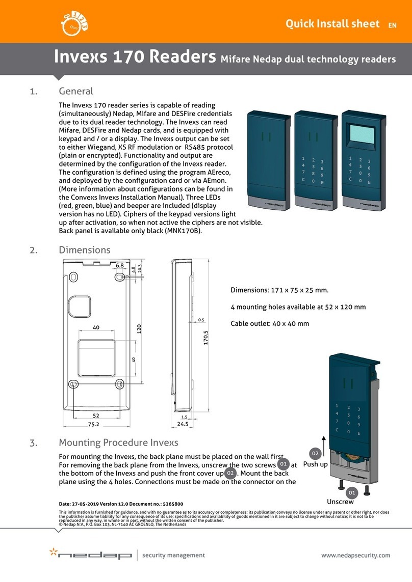
Nedap Invexs 170 Series Instructions for use
Nedap
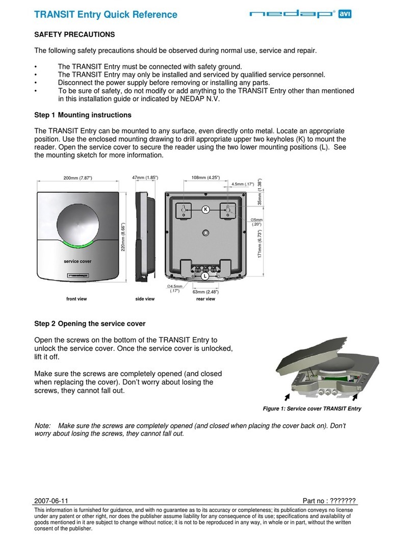
Nedap TRANSIT Entry User manual
Nedap
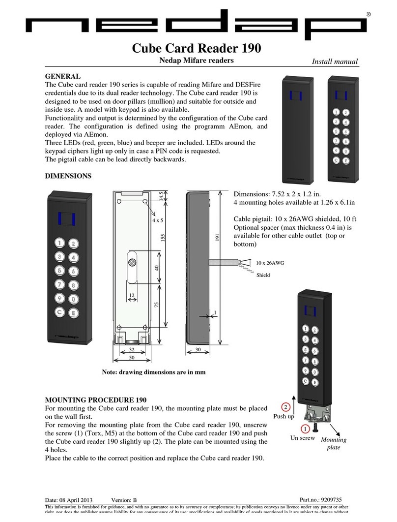
Nedap Cube Card Reader 190 Manual
Nedap
Nedap VP1006 User manual
Nedap
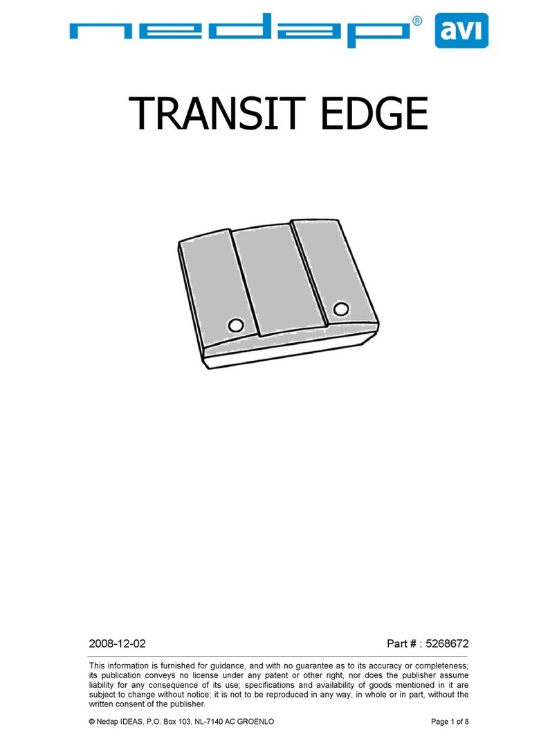
Nedap TRANSIT EDGE User manual


