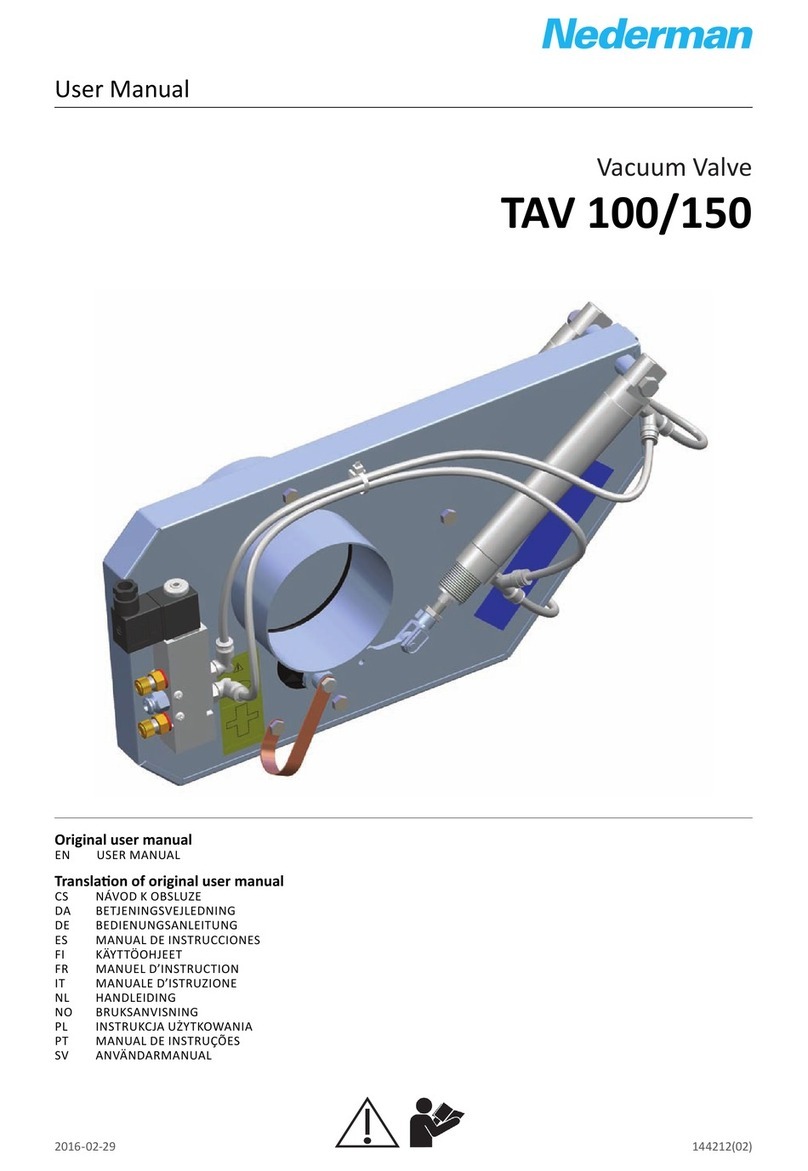
Nederman TAV 50 User manual

User Manual
Valves and accessories
Vacuum Valve TAV 50
Originaluser manual
EN USER MANUAL
Translation of originaluser manual
CS NÁVOD OBSLUZE
DA BRUGERVEJLEDNING
DE BEDIENUNGSANLEITUNG
ES MANUAL DE USUARIO
FI ÄYTTÖOHJE
FR MANUEL DE L'UTILISATEUR
HU FELHASZNÁLÓI ÉZI ÖNYV
IT MANUALE DELL'UTENTE
NL GEBRUI ERSHANDLEIDING
NO BRU ERMANUAL
PL INSTRU CJA OBSŁUGI
PT MANUAL DO UTILIZADOR
RU РУКОВОДСТВО ПО ЭКСПЛУАТАЦИИ
S NÁVOD NA OBSLUHU
SV ANVÄNDARMANUAL
2022-11-03 2130293 (03)
EN
CS
DA
DE
ES
FI
FR
HU
IT
NL
NO
PL
PT
RU
S
SV

Vacuum Valve TAV 50
Trace back information:
Workspace Main version a69
Published 2022-11-03 at 10:12:06
Skribenta version 5.5.022

Vacuum Valve TAV 50
Declaration of Conformity ........................................................ 4
Figures .......................................................................................... 8
English ........................................................................................... 15
Český ............................................................................................. 22
Dansk ............................................................................................. 30
Deutch ........................................................................................... 37
Español .......................................................................................... 46
Suomi ............................................................................................ 55
Français ......................................................................................... 62
Magyar .......................................................................................... 71
Italiano .......................................................................................... 80
Nederlands ................................................................................... 88
Norsk ............................................................................................. 97
Polski ............................................................................................. 104
Português ..................................................................................... 114
Русский ........................................................................................... 123
Slovensky ..................................................................................... 132
Svenska .........................................................................................140
3

Vacuum Valve TAV 50
Declaration of Conformity
EN English
Declaration of Conformity
We, AB Ph. Nederman & Co., declare under our sole responsibility that
the Nederman product:
Vacuum Valve TAV 50 (Part No. **, and stated versions of **) to which
this declaration relates, is in conformity with all the relevant provisions
of the following directives and standards:
Directives
2006/42/EC, 2014/30/EU, 2014/34/EU.
Standards
EN ISO 12100:2010, EN 60204-1:2018, EN 1127- 1:2019, EN
60079-0:2018, EN ISO 20607:2019, EN ISO 80079-36:2016, EN ISO
80079-37:2016.
The name and signature at the end of this document is the person re-
sponsible for both the declaration of conformity and the technical file.
CS Český
Prohlášení o Shodě
My, společnost AB Ph. Nederman & Co., prohlašujeme na svou zodpo-
vědnost, že výrobek Nederman:
Vacuum Valve TAV 50 (díl č. **, a uvedla, verze **), ke kterému se to-
to prohlášení vztahuje, je v souladu se všemi příslušnými ustanoveními
následujících směrnic a norem:
Směrnice
2006/42/EC, 2014/30/EU, 2014/34/EU.
Normy
EN ISO 12100:2010, EN 60204-1:2018, EN 1127- 1:2019, EN
60079-0:2018, EN ISO 20607:2019, EN ISO 80079-36:2016, EN ISO
80079-37:2016.
Na konci tohoto dokumentu je jméno a podpis osoby zodpovědné za
prohlášení o shodě a soubor technické dokumentace.
DA Dansk
Overensstemmelseserklæring
AB Ph. Nederman & Co., erklærer som eneansvarlige, at følgende pro-
dukt fra Nederman:
Vacuum Valve TAV 50 (Artikel nr. **, og erklærede versioner af **), som
denne erklæring vedrører, er i overensstemmelse med alle de relevan-
te bestemmelser i de følgende direktiver og standarder:
Direktiver
2006/42/EC, 2014/30/EU, 2014/34/EU.
Standarder
EN ISO 12100:2010, EN 60204-1:2018, EN 1127- 1:2019, EN
60079-0:2018, EN ISO 20607:2019, EN ISO 80079-36:2016, EN ISO
80079-37:2016.
Navnet og underskriften sidst i dette dokument tilhører den person,
der er ansvarlig for såvel overensstemmelseserklæringen som den tek-
niske dokumentation.
DE Deutch
onformitätserklärung
Wir, AB Ph. Nederman & Co., erklären in alleiniger Verantwortung, dass
das Nederman Produkt:
Vacuum Valve TAV 50 (Art.-Nr. **, und bauartgleiche Versionen **),
auf welches sich diese Erklärung bezieht, mit allen einschlägigen Be-
stimmungen der folgenden Richtlinien und Normen übereinstimmt:
Richtlinien
2006/42/EC, 2014/30/EU, 2014/34/EU.
Standards
EN ISO 12100:2010, EN 60204-1:2018, EN 1127- 1:2019, EN
60079-0:2018, EN ISO 20607:2019, EN ISO 80079-36:2016, EN ISO
80079-37:2016.
Der Name und die Unterschrift am Ende dieses Dokuments sind die für
die onformitätserklärung und die technischen Unterlagen verant-
wortlichen Personen.
ES Español
Declaración de Conformidad
Nosotros, AB Ph. Nederman & Co., declaramos bajo nuestra exclusiva
responsabilidad que el producto de Nederman,
Vacuum Valve TAV 50 (Ref. n.º ** y las versiones indicadas de **), al
que hace referencia esta declaración, cumple con todas las provisiones
relevantes de las Directivas y normas que se indican a continuación:
Directivas
2006/42/EC, 2014/30/EU, 2014/34/EU.
Normas
EN ISO 12100:2010, EN 60204-1:2018, EN 1127- 1:2019, EN
60079-0:2018, EN ISO 20607:2019, EN ISO 80079-36:2016, EN ISO
80079-37:2016.
El nombre y firma que figuran al final de este documento corresponden
a la persona responsable, tanto de la declaración como de la ficha técni-
ca.
FI Suomi
Vaatimustenmukaisuusvakuutus
Me, AB Ph. Nederman & Co., vakuutamme yksinomaan omalla vastuul-
lamme, että Nederman tuote:
Vacuum Valve TAV 50 (tuotenro ** ja **:n määritetyt versiot), jota tä-
mä vakuutus koskee, on seuraavien direktiivien ja standardien kaikkien
sovellettavien määräysten mukainen:
Direktiivit
2006/42/EC, 2014/30/EU, 2014/34/EU.
Standardit
EN ISO 12100:2010, EN 60204-1:2018, EN 1127- 1:2019, EN
60079-0:2018, EN ISO 20607:2019, EN ISO 80079-36:2016, EN ISO
80079-37:2016.
Tämä asiakirjan lopussa oleva nimi ja allekirjoitus ovat henkilön, joka
vastaa sekä vaatimuksenmukaisuusvakuutuksesta että teknisestä tie-
dostosta.
4

Vacuum Valve TAV 50
FR Français
Déclaration de Conformité
Nous, AB Ph. Nederman & Co., déclarons sous notre seule responsabili-
té que le produit Nederman :
Vacuum Valve TAV 50 (réf. ** et versions indiquées de **) auquel fait
référence la présente déclaration est en conformité avec toutes les dis-
positions applicables des directives et normes suivantes :
Directives
2006/42/EC, 2014/30/EU, 2014/34/EU.
Normes
EN ISO 12100:2010, EN 60204-1:2018, EN 1127- 1:2019, EN
60079-0:2018, EN ISO 20607:2019, EN ISO 80079-36:2016, EN ISO
80079-37:2016.
Le nom et la signature à la fin de ce document sont ceux de la personne
responsable de la déclaration de conformité et du fichier technique.
HU Magyar
Megfelelőségi Nyilatkozat
Az AB Ph. Nederman & Co. vállalat teljes felelőssége tudatában
kijelenti, hogy a(z):
Nederman (cikkszám: **, és módosított verziói **) termék, amelyre
ez a nyilatkozat vonatkozik, megfelel az alábbi irányelveknek és
szabványoknak:
Irányelvek
2006/42/EC, 2014/30/EU, 2014/34/EU.
Szabványok
EN ISO 12100:2010, EN 60204-1:2018, EN 1127- 1:2019, EN
60079-0:2018, EN ISO 20607:2019, EN ISO 80079-36:2016, EN ISO
80079-37:2016.
A dokumentum végén található név és aláírás a megfelelőségi
nyilatkozatért és a műszaki dokumentációért felelős személy neve és
aláírása.
IT Italiano
Dichiarazione di Conformità
AB Ph. Nederman & Co., dichiara sotto la propria esclusiva responsabili-
tà che il prodotto Nederman:
Vacuum Valve TAV 50 (Art. N. **, e le versioni di detto **) al quale è re-
lativa la presente dichiarazione, è conforme alle disposizioni delle se-
guenti direttive e normative:
Direttive
2006/42/EC, 2014/30/EU, 2014/34/EU.
Normative
EN ISO 12100:2010, EN 60204-1:2018, EN 1127- 1:2019, EN
60079-0:2018, EN ISO 20607:2019, EN ISO 80079-36:2016, EN ISO
80079-37:2016.
Il nome e la firma in calce al presente documento appartengono al re-
sponsabile della dichiarazione di conformità e della documentazione
tecnica.
NL Nederlands
Conformiteitsverklaring
Wij ,AB Ph. Nederman & Co., verklaren onder onze verantwoordelijkheid
dat het Nederman product:
Vacuum Valve TAV 50 (artikelnr. **, en vermelde uitvoeringen van **)
waarop deze verklaring betrekking heeft, in overeenstemming is met
alle relevante bepalingen van de volgende richtlijnen en normen:
Richtlijnen
2006/42/EC, 2014/30/EU, 2014/34/EU.
Normen
EN ISO 12100:2010, EN 60204-1:2018, EN 1127- 1:2019, EN
60079-0:2018, EN ISO 20607:2019, EN ISO 80079-36:2016, EN ISO
80079-37:2016.
Naam en handtekening onder dit document zijn van degene die verant-
woordelijk is voor zowel de Verklaring van Overeenstemming als het
technische document.
NO Norsk
Erklæring om Överensstemmelse
Vi, AB Ph. Nederman & Co., erklærer under vårt eneste ansvar at Neder-
man-produktet:
Vacuum Valve TAV 50 (delenr. **, og angitte versjoner av **) som den-
ne erklæringen vedrører, er i samsvar med alle relevante bestemmelser
i følgende direktiver og standarder:
Direktiver
2006/42/EC, 2014/30/EU, 2014/34/EU.
Standarder
EN ISO 12100:2010, EN 60204-1:2018, EN 1127- 1:2019, EN
60079-0:2018, EN ISO 20607:2019, EN ISO 80079-36:2016, EN ISO
80079-37:2016.
Navnet og signaturen på slutten av dette dokumentet er den som er
ansvarlig for både samsvarserklæringen og den tekniske filen.
PL Polski
Deklaracja Zgodności
My, AB Ph. Nederman & Co. niniejszym oświadczamy na naszą własną
odpowiedzialność, że Nederman produkt:
Vacuum Valve TAV 50 [nr części ** oraz wskazane wersje **], który jest
przedmiotem niniejszej deklaracji, spełnia wszystkie odpowiednie wy-
magania wymienionych niżej dyrektyw i norm:
Dyrektywy
2006/42/EC, 2014/30/EU, 2014/34/EU.
Normy
EN ISO 12100:2010, EN 60204-1:2018, EN 1127- 1:2019, EN
60079-0:2018, EN ISO 20607:2019, EN ISO 80079-36:2016, EN ISO
80079-37:2016.
Na końcu niniejszego dokumentu znajdują się imię i nazwisko oraz pod-
pis osoby odpowiedzialnej za deklarację zgodności oraz dokumentację
techniczną.
PT Português
Declaração de Conformidade
Nós, da AB Ph. Nederman & Co., declaramos sob nossa responsabilidade
exclusiva que o Nederman produto:
Vacuum Valve TAV 50 (peça nº **, e versões referidas de **) à qual esta
declaração se refere, está em conformidade com todas as disposições
relevantes das seguintes diretrizes e normas:
Directivas
2006/42/EC, 2014/30/EU, 2014/34/EU.
Normas
EN ISO 12100:2010, EN 60204-1:2018, EN 1127- 1:2019, EN
60079-0:2018, EN ISO 20607:2019, EN ISO 80079-36:2016, EN ISO
80079-37:2016.
O nome e a assinatura no fim deste documento é a pessoa responsável
pela declaração de conformidade e pelo arquivo técnico.
RU Русский
Декларация о соответствии
Компания AB Ph. Nederman & Co. со всей ответственностью заявляет, что
оборудование Nederman:
Nederman (№ по каталогу **, и заявил, версии **), к которому относится
данная декларация, соответствует всем требуемым положениям следующих
директив и стандартов.
Директивы
2006/42/EC, 2014/30/EU, 2014/34/EU.
Стандарты
EN ISO 12100:2010, EN 60204-1:2018, EN 1127- 1:2019, EN
60079-0:2018, EN ISO 20607:2019, EN ISO 80079-36:2016, EN ISO
80079-37:2016.
Сотрудник, поставивший свою подпись под данным документом, отвечает
как за соблюдение декларации о соответствии, так и за достоверность
технических данных.
5

Vacuum Valve TAV 50
S Slovensky
Vyhlásenie o Zhode
My, AB Ph. Nederman & Co., na vlastnú zodpovednosť vyhlasujeme, že
Nederman výrobok:
Vacuum Valve TAV 50 (č. dielu ** a oficiálna verzia **), ktorého sa to-
to vyhlásenie týka, je v zhode so všetkými príslušnými ustanoveniami
týchto smerníc a noriem:
Smernice
2006/42/EC, 2014/30/EU, 2014/34/EU.
Normy
EN ISO 12100:2010, EN 60204-1:2018, EN 1127- 1:2019, EN
60079-0:2018, EN ISO 20607:2019, EN ISO 80079-36:2016, EN ISO
80079-37:2016.
Meno a podpis na konci tohto dokumentu patria osobe zodpovednej za
vyhlásenie o zhode a technickú dokumentáciu.
SV Svenska
Överensstämmelsedeklaration
Vi, AB Ph. Nederman & Co., förklarar under vårt fulla ansvar att Neder-
man-produkten:
Vacuum Valve TAV 50 (artikelnummer **, och angivna versioner av **)
som denna deklaration avser, är i överensstämmelse med alla relevanta
bestämmelser i följande direktiv och standarder:
Direktiv
2006/42/EC, 2014/30/EU, 2014/34/EU.
Standarder
EN ISO 12100:2010, EN 60204-1:2018, EN 1127- 1:2019, EN
60079-0:2018, EN ISO 20607:2019, EN ISO 80079-36:2016, EN ISO
80079-37:2016.
Namnet och signaturen i slutet av detta dokument är den person som
ansvarar för både försäkran om överensstämmelse och den tekniska fi-
len.
**
2156507, 40147040, 40060100, 40060110, 40147050, 40147060, 40147020, 40147030, 40060120, 40147060, 40147071, 40060140,
40147090, 40060130, 40147100, 40147110, 40147120
AB Ph. Nederman & Co.
P.O. Box 602
SE-251 06 Helsingborg
Sweden
Anna Cederlund
Product Center Manager
Technical Product Management
2022-11-03
6

Vacuum Valve TAV 50
U Declaration of Conformity
We, AB Ph. Nederman & Co., declare under our sole responsibility that the Nederman product:
Vacuum Valve TAV 50 (Part No. **, and stated versions of **) to which this declaration relates, is in conformity with all the relevant
provisions of the following regulations and standards:
Relevant legislation
Supply of Machinery (Safety) Regulations 2008, Electromagnetic Compatibility Regulations 2016, Equipment and Protective Sys-
tems Intended for use in Potentially Explosive Atmospheres Regulations 2016
Standards
EN ISO 12100:2010, EN 60204-1:2018, EN 1127- 1:2019, EN 60079-0:2018, EN ISO 20607:2019, EN ISO 80079-36:2016, EN ISO
80079-37:2016.
The name and signature at the end of this document is the person responsible for the declaration of conformity.
The U importer is authorised and responsible to compile the technical file.
**
2156507, 40147040, 40060100, 40060110, 40147050, 40147060, 40147020, 40147030, 40060120, 40147060, 40147071,
40060140, 40147090, 40060130, 40147100, 40147110, 40147120
AB Ph. Nederman & Co.
P.O. Box 602
SE-251 06 Helsingborg
Sweden
Anna Cederlund
Product Center Manager
Technical Product Management
2022-11-03
U Importer:
Nederman Ltd
91 Seedlee Road,
Walton Summit Centre,
Bamber Bridge,
Preston,
Lancashire,
PR5 8AE
7

Vacuum Valve TAV 50
Figures
TAV 50 PC
TAV 50 MV
TAV 50 MV-W
TAV 50 FV/MV
TAV 50 FV
TAV 50 MA
TAV 50 FV/MV-G
+A
TAV 50 MV-G
+A
Models
8

Vacuum Valve TAV 50
11
2
3
4
5
1
6
10
7 8
9
1
2
5
3
4
1
2
3 4
9

Vacuum Valve TAV 50
5c
5d
5b
5a
5e
5
+
Min: 0.5 MPa (5 bar) 70 PSI
Max: 1 MP (10 bar) 145 PSI
6
7d
7b 7c
A B
A B
B A
B A
7a
50 mm
7
10

Vacuum Valve TAV 50
TAV 50 PC
P
B
C
8
TAV 50 MA
B
9
TAV 50
MV
P
TAV
50 MV-G
B
A
10
11

Vacuum Valve TAV 50
TAV 50 MV-W
P
24V AC
B
11
TAV 50 FV
P
B
12
TAV 50
FV/MV
P
TAV 50 FV/MV-G
B
A
13
12

Vacuum Valve TAV 50
14
175
95 195
120
68
25
87.5
15
12345
16
ab
17
13

Vacuum Valve TAV 50
14

Vacuum Valve TAV 50
English
User Manual
Table of contents
Figures ............................................................................................................................................................................. 8
1 Product marking ............................................................................................................................................................ 16
1.1 Type of Protection constructional safety “c” ................................................................................................ 17
2 Preface ............................................................................................................................................................................ 17
3 Safety .............................................................................................................................................................................. 17
3.1 Classification of important information ......................................................................................................... 17
4 Description ..................................................................................................................................................................... 17
4.1 Main components ............................................................................................................................................... 17
4.2 ATEX products .................................................................................................................................................... 18
4.3 Category limit ...................................................................................................................................................... 18
4.4 Permitted materials ........................................................................................................................................... 18
4.5 Technical data ..................................................................................................................................................... 18
5 Installation ...................................................................................................................................................................... 19
5.1 Pressure drop ...................................................................................................................................................... 19
5.2 Mounting ............................................................................................................................................................. 19
5.3 Electrical installation ......................................................................................................................................... 19
5.4 Connections ........................................................................................................................................................ 19
6 Using Vacuum Valve TAV 50 ....................................................................................................................................... 20
7 Maintenance .................................................................................................................................................................. 20
8 Flow Sensing Valve ....................................................................................................................................................... 20
8.1 Technical data ..................................................................................................................................................... 20
8.2 Description .......................................................................................................................................................... 20
8.3 Main components ............................................................................................................................................... 20
8.4 Function ............................................................................................................................................................... 21
8.5 Connection .......................................................................................................................................................... 21
8.6 Maintenance ....................................................................................................................................................... 21
9 Accessories ..................................................................................................................................................................... 21
9.1 Accessories in classified locations (ATEX) .................................................................................................... 21
10 Spare Parts ..................................................................................................................................................................... 21
10.1 Ordering spare parts .......................................................................................................................................... 21
11 Recycling ......................................................................................................................................................................... 21
EN
15

Vacuum Valve TAV 50
EN 1Product marking
The following products are not ATEX-classified and are only marked with the CE label:
• TAV 50 MA (see Description ATEX-products)
• TAV 50 MV-W
• TAV 50 MV 24V AC/DC
• TAV 50 FV/MV 24V AC/DC
The following products are ATEX-classified and are marked according to the description:
• TAV 50 PC
• TAV 50 FV
• TAV 50 MV 115V AC, 230V AC, 24V DC
• TAV 50 FV/MV 115V AC, 230V AC, 24V DC
II 3D Ex h IIIC T130ºC Dc
0ºC≤Ta≤40ºC
Nederman 19.HB06
Part Explanation
II: From ATEX directive, Equipment group non-mining equipment.
3D: From ATEX directive, Equipment category 3D intended for use with combustible
dust in zone 22.
h: The letter ”h” as specified in EN ISO 80079-36.
IIIC: Equipment of Group III is intended for use in places with an explosive dust atmo-
sphere other than mines susceptible to firedamp.
Equipment of Group III is subdivided according to the nature of the explosive dust
atmosphere for which it is intended.
Group III subdivisions:
• IIIA : suitable for combustible flyings;
• IIIB : suitable for combustible flyings and non-conductive dust;
• IIIC : suitable for combustible flyings, non-conductive dust, and conductive
dust.
T130ºC The maximum surface temperature in degrees Celsius.
Dc: Equipment protection level Dc. Same as ATEX directive Equipment category 3D.
For explosive atmospheres, caused by mixtures of air and combustible dust, the
equipment does not contain any effective ignition sources in normal operation.
0ºC≤Ta≤40ºC Ambient temperature range.
Nederman 19.HB06 Certificate number.
16

Vacuum Valve TAV 50
1.1Type of Protection constructional
safety “c”
Technical documentation contains the information re-
quired to maintain product safety.
2Preface
Thank you for using a Nederman product!
The Nederman Group is a world-leading supplier and
developer of products and solutions for the environ-
mental technology sector. Our innovative products
will filter, clean and recycle in the most demanding of
environments. Nederman's products and solutions will
help you improve your productivity, reduce costs and
also reduce the impact on the environment from in-
dustrial processes.
Read all product documentation and the product iden-
tification plate carefully before installation, use, and
service of this product. Replace documentation imme-
diately if lost. Nederman reserves the right, without
previous notice, to modify and improve its products
including documentation.
This product is designed to meet the requirements
of relevant EC directives. To maintain this status, all
installation, maintenance, and repair is to be done
by qualified personnel using only Nederman original
spare parts and accessories. Contact the nearest au-
thorized distributor or Nederman for advice on tech-
nical service and obtaining spare parts. If there are
any damaged or missing parts when the product is de-
livered, notify the carrier and the local Nederman rep-
resentative immediately.
3Safety
3.1Classification of important informa-
tion
This document contains important information that
is presented either as a warning, caution or note, ac-
cording to the following examples:
WARNING!Risk of personal injury
Warnings indicate a potential hazard to the
health and safety of personnel, and how that
hazard may be avoided.
CAUTION!Risk of equipment damage
Cautions indicate a potential hazard to the
product but not to personnel, and how that
hazard may be avoided.
NOTE!
Notes contain other information that is import-
ant for personnel.
4Description
TAV 50 is a valve for automatic opening and closing of
a vacuum outlet linked to a central vacuum system. It
comes in six different models, see FigureModels. The
valves are normally automatic, they open and close
governed by a control device.
Figure3 shows TAV 50 in the open position. Com-
pressed air turns the blade when an air signal is ap-
plied to the connection nipple. Figure4 shows the
closed position. The return spring turns the blade back
to this position as soon as the air signal is removed.
The nylon sealing rings supported by the backup rings
seal off against the blade in the open and closed posi-
tions. The backup rings are made of neoprene but are
also available in Viton for extremely difficult applica-
tions.
The control device can be a solenoid valve for electric
control or a flow sensing valve sensing the flow to a
compressed air tool. TAV 50 PC (basic version) is not
fitted with its own control device but an external 3-
port valve is available as an option, see FigureModels,
Figure8, Figure9 and ,Figure10. All versions are com-
pressed air powered except for TAV 50 MA, it requires
no compressed air but is equipped with a lever for the
operation of the valve.
TAV 50 can be fitted with a micro switch to control
the vacuum unit, see Chapter9Accessories. The flow
sensing valve (FV) is described in Chapter8Flow
Sensing Valve.
NOTE!
The current sensing device, item A in Fig-
ureModels, is designed as a control device
for TAV 50. For more information, see
w$w$w$.$n$e$d$e$r$m$a$n$.$c$o$m$.
4.1Main components
Figure1 shows a sectioned TAV 50.
1 Housing, lower part
2 Housing, upper part
3 Valve blade
4 Sealing ring
5 Backup ring
6 Arm
7 Piston
8 Cylinder (integrated into lower part)
9 Return spring
10 Connection nipple
11 Microswitch holder
Figure2 shows the most common control devices.
1 3-port valve for remote control of TAV 50 PC in the
basic version
2 Lever (MA)
3 Flow sensing valve (FV)
4 Solenoid valve (MV)
5 Sensor ring, solenoid valve and connection box
(Part of MV-W)
EN
17

Vacuum Valve TAV 50
EN 4.2ATEX products
All versions of TAV 50 are marked with the CE label.
Depending on the model and purpose of use, some
TAV 50 also have the EX symbol and category mark-
ing. All TAV 50 marked with the EX symbol are cat-
egory 3D equipment according to directive 2014/34/
EU. This means that models with the EX symbol may
be placed in areas classified as zone 22 according to
directive 1999/92/EC.
The manually operated TAV 50 MA is not marked with
the EX symbol as manually operated equipment does
NOT fall under the scope of the directive 2014/34/EU.
Even if the TAV 50 MA does not have the EX marking,
it is highly suitable for use in areas classified as zone
22 and share the same high level of protection as the
TAV 50 with EX marking.
NOTE!
TAV 50 MV-W and TAV 50 MV 24 V AC/DC does
not have the EX marking and may not be in-
stalled in classified areas.
4.3Category limit
The function of the TAV 50 is to be a part of an extrac-
tion piping system. Even if the TAV 50 with EX symbol
is category 3D equipment for use in zone 22 (TAV 50
exterior), it can be used with a piping system intern-
ally classified as zone 20 or 21. As there is no intern-
al ignition source inside the TAV 50, it is to be con-
sidered as simple piping and does not fall under the
scope of the directive 2014/34/EU.
4.4Permitted materials
The TAV 50 is only intended to be a part of an ex-
traction system transporting dust with the following
properties: MIE (Minimum Ignition Energy) > 3 mJ and
MIT (Minimum Ignition Temperature) > 205°C. Do not
extract items that may cause ignition or blocking.
4.5Technical data
Maximum pressure 1 MPa (10 bar)
Minimum pressure (for safe
operation) 0.5 MPa (5 bar)
Recommended pressure 0.6–0.7 MPa (6–7 bar)
Maximum airflow (flow valve) 1800 Nl/min.
Minimum airflow (flow valve) 100 Nl/min.
Air quality ISO 8573-1 class 5
Working temperature 0–40 °C (32 F to 104 F)
Wiring gauge minimum of 0.75 mm2
Solenoid voltages 115 V AC (+10% -15%) 230 V AC (+10% -15%) 24 V DC (+ -10%) or 24 V
AC/DC (not ATEX)
Frequency 50 / 60 Hz for AC
Equipment type II 3D Ex h IIIC T130ºC Dc 0ºC≤Ta≤40ºC Nederman 19.HB06 (ATEX-products)
Diameter, inner 51 mm (2")
Diameter, outer 63 mm (2.5")
18

Vacuum Valve TAV 50
5Installation
WARNING!Risk of personal injury
Use ear protection and safety goggles.
5.1Pressure drop
For pressure drop calculations, count the open TAV 50
in a straight piece of duct with Ø50 mm and a length of
300 mm.
5.2Mounting
For wall mounting, positioning as per Figure5a is
recommended. Flow direction is normally upwards
but the reverse direction is also possible. Mounting
shown in Figure5b is also possible but positioning
“upside-down” (Figure5c) should be avoided. Sup-
plied support brackets should always be used for wall
mounting, see arrows in Figure5d.
NOTE!
The compressed air pipe should be blown clean
before connecting the valve. See Figure6. New
pipes always contain dirt that can cause mal-
function.
CAUTION!Risk of equipment damage
The valve must not bare the load of connection
pipes or other connections which may cause
defects on the valve. Make sure the connec-
tions are firmly installed against the wall, ceil-
ing, floor or suchlike. Hose connections must
be strain relieved.
Mounting in a type SA swing arm is made as shown
in Figure5e using threaded holes in the swing arm
bracket. The support brackets should not be used in
this case.
A compressed air filter should be installed if air qual-
ity is poor. A lubricator is not necessary but may be in-
stalled in front of the TAV 50 FV if the air tool linked to
it requires oiling.
5.3Electrical installation
To ensure proper function and required level of pro-
tection with regards to the equipment category, make
sure that the following points are checked:
• The electrical installation and connection of the
magnetic valve must be done by a certified electri-
cian. A certified electrician must also pay attention
to the conditions for installations in zones classified
according to ATEX.
• Check that proper measures have been taken to
avoid all types of electrical stray currents to and/
or from the piping system and electrical wiring.
Note that the TAV 50 housing is made of conductive
plastic material and must be properly grounded.
• Connected hoses or piping must be conductive and
grounded to the TAV 50 studs (see Figure7a–d).
• Check that the correct voltage is connected to the
solenoid of the magnetic valve. Check the marking
on the solenoid.
• Electrical options, like micro switches, must be con-
nected to an intrinsic safe circuit (for options in-
stalled in ATEX classified zones).
WARNING!Risk of electric shock, over-
heating or possible fire
All wiring must be connected at the correct
connection points (Phase, Neutral and Ground).
Do not connect mains (phase) to the solenoid
ground.
5.4Connections
WARNING!Risk of personal injury
Maximum recommended air pressure is 1 MPa
(10 bars). A pressure regulator must be in-
stalled if the pressure is likely to exceed the
maximum pressure. Recommended work-
ing pressure is 0.6–0.7 MPa (6–7 bars). Min.
pressure for a reliable function is 0.5 MPa (5
bars). Compressed air hoses must be approved
for the actual pressure and must be securely
fastened to the valve nipples. Hose clips must
be fitted correctly.
Figure8 to Figure13 explain how to connect TAV
valves having different control devices. A “flash ar-
row” indicates an electric supply. P indicates a com-
pressed air supply.
• TAV 50 PC (Figure8) is not fitted with its own con-
trol device. It is intended for direct control with a re-
mote 3-port pilot valve (option).
• TAV 50 MA (Figure9) is controlled by a hand-oper-
ated lever. It is used when there is no need for auto-
matic controlling.
• TAV 50 MV (Figure10) has a solenoid valve control
device. The solenoid voltage must match the signal
voltage. TAV 50 MV can be directly controlled by a
stationary electric machine. However, extra branch
fuses should be used if the mains fuses are too large
for this function. See rated voltage and power on
the solenoid. TAV 50 MV can also be controlled by a
handheld electric tool. A current sensing relay (op-
tion, see item A in FigureModels) must be installed
in this case.
• TAV 50 MV-W (Figure11) is supplied with a control
device consisting of a 24 V AC solenoid, a control
box and a sensor ring that can detect a welding cur-
rent. Each valve must be supplied with 24 V AC from
a transformer (optional), that can be shared by a
number of valves.
• TAV 50 FV (Figure12) carries a control device in
the form of a flow sensing valve. This option is used
when TAV 50 is to open for compressed airflow, for
example to an air tool.
EN
19

Vacuum Valve TAV 50
EN • TAV 50 FV/MV (Figure13) features two control
devices, a flow sensing valve, and a solenoid valve. It
can be controlled by an electric signal as well as by a
compressed airflow.
6 Using Vacuum Valve TAV 50
WARNING!Risk of personal injury
• eep fingers clear off the vacuum connec-
tions when the valve is connected to com-
pressed air. The spring that closes the valve
is strong enough to cause discomfort.
• Make sure the system does not transport ma-
terial which can damage the TAV valve.
• If an unexpected object comes into the sys-
tem, shut the compressed air supply to the
valve immediately and remove the object.
7Maintenance
Installation, repair and maintenance work is to be car-
ried out by qualified personnel using only the original
Nederman spare parts. Contact your nearest author-
ized distributor or Nederman for advice on technical
service.
WARNING!Risk of personal injury
• Disconnect voltage prior to service.
• The compressed air supply must be discon-
nected and any remaining pressure in the
valve discharged before commencing any
maintenance work to the valve. A shut-off
valve before each TAV 50 valve is recommen-
ded.
• The compressed air supply to the TAV 50 valve must
be dry and clean (according to standard ISO 8573-1
class 5). Dirt may result in malfunction by clogging
the control device or the air cylinder inlet. Installing
an air filter may be necessary if clogging occurs.
• Make sure the inside of the valve and the connec-
tion pipes are free from deposits. A build-up of de-
posits inside the piping system may cause a dis-
charge of static electricity.
• Make sure the outside of the TAV valve, and particu-
larly the solenoid, are free from dust layers.
• Oily and sticky substances can sometimes stick to
the valve blade resulting in jamming so that the
valve does not close completely. The valve must
then be dismantled for cleaning.
• The backup rings of chloroprene are resistant to
most substances in reasonable quantities. Oil in a
large quantity can cause swelling to the rings result-
ing in jamming.
• After a million operations, the nylon sealing rings
should be exchanged in order to avoid leakage.
• The piston sealing ring needs changing if internal
leakage occurs in the air cylinder. A small quantity of
a silicon-free pneumatic grease, for example, Microl-
ube GL 261, should be applied to the new ring be-
fore assembly.
• The flow sensing valve (FV) is detailed in
Chapter8Flow Sensing Valve.
To ensure the required level of protection with re-
gards to the equipment category, specifically in ATEX
classified zones, check the following points regu-
larely, at least once a year:
• Inspect the TAV 50 parts described in Figure1 for
damage or malfunction. If the TAV 50 is damaged it
must removed immediately from the classified area,
while it is being repaired or replaced.
• Ensure that no explosive atmosphere and/or dust
layers are present when cleaning, servicing or in-
specting the TAV.
• Ensure that only original (OEM) spare parts are used.
• Ensure that the TAV 50 is not covered with thick
dust layers (>5 mm). This is prevented by setting up
routines for regular cleaning and including these in
the explosion protection document.
8Flow Sensing Valve
The Flow Sensing Valve comes with TAV 50 FV and
TAV 50 FV/MV by delivery.
8.1Technical data
Maximum pressure 1 MPa (10 bar)
Minimum pressure (for
safe operation) 0.5 MPa (5 bar)
Recommended pressure 0.6–0.7 MPa (6–7 bar)
Maximum airflow (flow
valve) 1800 Nl/min
Minimum airflow (flow
valve) 100 Nl/min
8.2Description
The flow sensing valve senses the flow of compressed
air through the valve and gives an air signal at the out-
put nipple. The valve is normally used for controlling
TAV 50 but can also be used whenever an airflow
should control a process. It is fitted with nipples for 13
mm (1/2”) hose. The pressure drop across the valve is
normally small enough to be neglected.
8.3Main components
Figure16 shows a partly disassembled valve.
1 Housing with fitted angle output nipple
2 Piston
3 Spring
4 Bottom lid
20
This manual suits for next models
8
Table of contents
Languages:
Other Nederman Control Unit manuals
Popular Control Unit manuals by other brands

Elvox
Elvox 80P1 Installation and operation manual

Texas Instruments
Texas Instruments LM27341 user guide

Mosconi
Mosconi AMAS-96K owner's manual

Multiplex
Multiplex M-Link HFMG1 operating instructions

ProSoft Technology
ProSoft Technology inRax MVI56-DNPSNET user manual

National Instruments
National Instruments NI USB-9201 USER GUIDE AND SPECIFICATIONS