nekos K-LOCK User manual

4420088 – Rev. 1710
K-LOCK
INSTRUCTION MANUAL
ELECTROMECHANICAL LOCK
Force 600N – Strokes 18 - 36 mm
Electrical feeding 24V
EN
2
nekos products have been manufactured in accordance with safety standards and conforms to the
stipulations of current standards in force.
When correctly assembled, installed and used according to the present instructions, they will not
generate any danger for persons, animals or items.
Symbols used in the manual
DANGER
This indication draw the attention about potential dangers for safety and
health of peoples and animals.
INFORMATION
This information give further suggestions.
ATTENTION
This indication draw the attention about potential dangers for the product
itself.
WARNING
This indication draw the attention about potential damages to goods.
ENVIRONMENTAL
INSTRUCTION
Environmental indication draw the attention about potential dangers for
the environment.

3
Contents
1. SECURITY RULES....................................................................................................................... 4
2. TECHNICAL INFORMATION FOR APPLICATION AND OPERATION ..................................... 5
3. TECHNICAL DATA ....................................................................................................................... 5
4. CONSTRUCTION AND REGULATORY REFERENCES ............................................................ 6
5. ID PLATE AND MARKING DATA ................................................................................................ 6
6. ELECTRIC POWER SUPPLY ...................................................................................................... 7
7. SETTING THE DIP-SWITCHES – Selecting the stroke and setting the operating mode........... 7
8. ASSEMBLY INSTRUCTIONS ...................................................................................................... 8
8.1. Preparation of actuator for assembly .................................................................................... 9
8.2. Installation ............................................................................................................................. 9
8.2.1. Milling of the seats for recessed assembly ................................................................. 9
8.2.2. Recessed assembly................................................................................................... 10
8.2.3. Drilling for external assembly .................................................................................... 10
8.2.4. External assembly ..................................................................................................... 10
9. ELECTRICAL CONNECTION .................................................................................................... 11
10. START-UP OPERATIONS ........................................................................................................ 11
10.1. With actuator .................................................................................................................... 11
10.2. Without actuator (test) ...................................................................................................... 12
11. MAINTENANCE OR CLEANING ............................................................................................... 12
12. EMERGENCY OPERATIONS OR MALFUNCTIONS ............................................................... 12
12.1. Emergency operations ...................................................................................................... 12
12.2. Malfunctions of the device ................................................................................................ 12
12.3. LED Light signals .............................................................................................................. 13
13. ENVIRONMENTAL PROTECTION ............................................................................................ 14
14. CERTIFICATE OF GUARANTEE .............................................................................................. 14
15. DECLARATION OF INCORPORATION (for a partly completed machine) AND EC
DECLARATION OF CONFORMITY .......................................................................................... 15
4
1. SECURITY RULES
PLEASE NOTE: IMPORTANT SAFETY INSTRUCTIONS. CAREFULLY OBSERVE ALL THE
FOLLOWING INSTALLATION INSTRUCTIONS TO ENSURE PERSONAL SAFETY. IMPROPER
INSTALLATION CAN SERIOUSLY ENDANGER SAFETY. KEEP THESE INSTRUCTIONS AFTER
INSTALLATION.
MANDATORY RISK ANALYSIS AND PROTECTION MEASURES.
The Nekos electrical actuators comply with the Machinery Directive (2006/42/EC), Standard IEC
60335-2-103 (Particular requirements for drives for gates, doors and windows) and other directives
and regulations indicated in the attached Declarations of Incorporation and CE Conformity (at the
end of the manual). According to the Machinery Directive, actuators are “partly completed
machinery” intended for incorporation into doors and windows. The manufacturer/supplier of the
window is required, with exclusive responsibility, to ensure the compliance of the entire system
with the applicable standards and to issue CE certification. We strongly discourage any use of the
actuators other than that specified and therefore, in any case, the supplier of the complete system
retains full liability.
For systems installed at a height of less than 2.5 m above floor level or other levels accessible to
users, the manufacturer/supplier of the window must conduct risk analysis regarding potential
harm (violent blows, crushing, wounds) caused to people by normal use or possible malfunction or
accidental breakage of the automated windows, and to implement suitable protective measures in
view of these. Such measures include those recommended by the specified standard:
- controlling the actuators via a “deadman’s button” placed near the system and within the
operator’s field of view, to ensure that people are out of the way during operation. The button
should be placed at a height of 1.5 m and operated by key if accessible to the public; or:
- use of contact safety systems (also included in the actuators) that ensure a maximum closing
force of 400/150/25 N, measured in accordance with paragraph BB.20.107.2 of IEC 60335-2-
103; or:
- use of non-contact safety systems (lasers, light grids); or:
- use of fixed safety barriers that prevent access to moving parts.
Automated windows are deemed adequately protected if they:
- are installed at a height of >2.5 m; or:
- have a leading-edge opening of <200 mm and a closing speed of <15 mm/s; or:
- are part of a smoke and heat evacuation system for emergency use only.
In any case, moving parts of windows that could fall below 2.5 m following breakage of a system
component need to be fixed or secured in order to prevent them from suddenly falling or
collapsing: e.g. the use of safety arms on bottom-hung windows.
The device is not intended for use by persons (including children) with reduced physical,
sensory or mental capabilities, or lacking experience and knowledge. Do not allow children
to play with the fixed controls and keep any remote-control units out of their reach.
The actuator is destined exclusively for installation indoors. For any special application we
recommend you consult the manufacturer beforehand.
After removing packaging, check for any damage on the appliance.
MAINTENANCE and REPAIRS
Periodically check the installation by inspecting the cables, springs, rods and mechanical
parts for wear or damage. Do not use if repair or adjustment is required.
Disconnect the power supply during cleaning or maintenance operations.
Do not use solvents or jets of water to wash the appliance. The appliance should not be
submerged in water.
In the event of breakage or malfunction, switch the appliance off at the general switch and
call for the services of a qualified technician.

5
Repairs should only be performed by qualified personnel at assistance centres authorised
by the manufacturer.
Always request exclusive use of original spare parts. Failure to respect this condition could
compromise safety and invalidate the benefits contained in the warranty for the appliance.
In the event of any problems or queries, consult your agent or contact the manufacturer
directly.
2. TECHNICAL INFORMATION FOR APPLICATION AND OPERATION
The K-LOCK electromechanical lock is a technical development for automatic locking of
windows, continuous facades and doors. It can be adapted to almost any type of profile in
aluminium, PVC or wood and performs the forward / backward movement of the sliding
accessory of a window or door.
Mounted by itself the device is an effective protection against intrusion, blocking the latch of
windows and doors, but it’s actually constructed to interface only with 24V chain actuators
of the INKA 356 series, even in the SYNCRO³ version, in natural ventilation and smoke and heat
exhaust systems (RWA). The reduced cross-section (just 25x25 mm) allows recessed
insertion in the profiles.
K-LOCK can be combined with the 230V~ actuators of the INKA 356 series (SOLO and
SYNCRO³ versions) by requesting, when placing the order for the actuators, the inclusion of a
small interface device.
The electromechanical lock is composed of a linear actuator that moves the locking hook of
the sliding accessory, with a selectable stroke of 18 or 36 mm. The easy-to-install mechanisms
can be recessed or mounted externally with just two screws.
In combination with the 24V actuators of the INKA 356 series, the device is certifiable under
standard EN 12101-2 – (Smoke and heat control systems – Part 2: Specifications for natural
smoke and heat exhaust ventilators).
3. TECHNICAL DATA
Model K-LOCK 24V
Push and pull force 600 N - 850 N starting force
Strokes 18 mm / 36 mm
Power supply voltage 24V (20,4÷28,8V )
Current absorbed at nominal load 0,85 A during the stroke
1,2 A at intervention of the current interlock
Power absorbed at nominal load ~ 20 W
No-load speed 5 mm/s
No-load stroke time 4 s (18 mm) – 7.2 s (36 mm)
Double electrical insulation Extra-low voltage (SELV) device
Insertion ratio 30 %
Service S
2
of 1 minute
Structure material Extruded aluminium alloy
Operating temperature -20°C - +70°C
Degree of protection for electrical devices IP 40
Opening and closing stroke-end Electronical by means of dip-switches
Operation with chain actuator Selectable
Operation without actuator Selectable
Power supply cable in SILICONE 3x0,5 mm² - 2,00 m
Open/Close overload protection Current cut-off due to power absorption
Dimensions (mm) 25.5 x 25.5 x 357
Weight (kg) 0.560
The data provided in these illustrations is non-binding and subject to change, even without advance notice.
6
4. CONSTRUCTION AND REGULATORY REFERENCES
INTENDED USE.
The
K
-
LOCK
lock has been designed and constructed to move
any sliding accessory, available on the market, applied to doors or windows that
have a coupling cylinder with Ø8; any other use is strongly discouraged, with the
supplier of the entire system in any case retaining sole liability.
The appliance is manufactured in accordance with the EC Directives and
Regulations listed in the attached Declaration of Incorporation and Conformity .
Pour assurer une déconnexion efficace du secteur, il est conseillé d’installer un
poussoir « homme mort » bipolaire de type agréé. En amont de la ligne de
commande, un interrupteur général d’alimentation omnipolaire avec ouverture des
contacts d’au moins 3 mm sera prévu.
- The electromechanical lock is constructed according to European Union
directives and certified in conformity with the mark.
- Any service or control device must be manufactured according to current
regulations and in compliance with EC standards.
The electromechanical lock is composed of a small linear actuator that moves the locking
hook with a 2 m cable in silicone with three wires.
General dimensions of the linear electric actuator
Always mount the latching plate under the hook.
The device is packaged in a cardboard box that contains:
One linear electric actuator, having a stroke of 18 and 36 mm, with a 2 m cable.
Package of small metal parts.
Instructions manual.
5. ID PLATE AND MARKING DATA
The Machine Directive classifies actuators as “partly completed machinery” and they are
supplied with a Declaration of Incorporation, attached to this booklet; with regard to the
electrical side, they bear marking and come under the LVD and CEM Directives and the
Stroke adjusting
dip-switch stopper

7
other Regulations listed in the attached Declaration of Conformity. With this marking, the
actuators can be sold and used throughout the European Union with no further
requirements. The plate data is displayed on an adhesive label placed on the outside of the
container, printed in black on a grey background.
←
Note!
The label is attached to the actuator; when mounted, the label is not visible.
6. ELECTRIC POWER SUPPLY
Risk of electric shock.
- Comply with the CE standards for electrical installation.
- The electrical connection must comply with current standards on the design
and implementation of electrical systems.
- Disconnect the electric power supply before carrying out any electrical
connection work.
Risk of destroying the motor.
The device requires a voltage of 24V . Higher voltage may destroy the motor.
- Low-voltage line and power line must be separate.
The lock must be powered with a voltage of 24V . The power supply cable has three
wires with red copper conductor, sheathing and insulating core in silicone, where:
BLACK “1” connected to the + (positive) CLOSE;
BLACK “2” connected to the + (positive) OPEN;
BLACK “3” is the communication signal with the chain actuator.
The electromechanical lock must be powered using a station with emergency batteries or a
security power supply unit with an output voltage of 24V (min. 20.4V, max. 30V).
7. SETTING THE DIP-SWITCHES – Selecting the stroke and setting the
operating mode.
The programming dip-switches are located under the cap on the side of the hook. The
selection is made using a small screwdriver or tweezers.
Dip-switch n. 1
This dip-switch is used to set two different strokes of the hook: 18 or 36
mm. The selection is determined by the type of application. The hook
must completely free the bolt of the sliding accessory by at least 3-5 mm.
The dip-switch:
- when placed in the ON position, sets the stroke to 18 mm:
- when placed in the OFF position, sets the stroke to 36 mm.
Dip-switch n. 2
This is the dip-switch that allows the user to select the operating mode:
“with actuator” or “ free” (without actuator). This dip-switch:
when placed in the OFF position, the OPEN / CLOSE movement of
the hook occurs according to the polarity of the power supply
between wire1 and wire2: wire1 +24V → CLOSE, wire1 -24V
→ OPEN.
This mode is useful during assembly or testing when there’s no
communication with the actuators; it’s also useful for performing a
test in the event of accidental fault or lack of operation.
8
when placed in the ON position, it dialogues with the chain
actuator according to the operating logic sequence.
In this case the lock moves only when the chain of the actuator
has re-entered completely.
It’s advisable to select the stroke and operating mode before installation and
ensure that the dip-switches are always accessible.
Stroke 18 mm. The key of the dip-switch should be moved to the ON position towards the
power supply cable.
Stroke 36 mm. The key of the dip-switch should be moved to the OFF position opposite
the power supply cable.
The factory settings are the following: dip1 = ON, dip2 = OFF.
8. ASSEMBLY INSTRUCTIONS
These instructions are intended for technical and specialized personnel, therefore
basic safety and working techniques are not discussed.
All operations for preparation, assembly and electrical connection must be carried out by
technical and specialized personnel; this will guarantee optimum performance and proper
operation of the electromechanical lock. First check that these fundamental conditions are met:
The performance of the electromechanical lock must be sufficient to move the
sliding accessory without any obstruction whatsoever; the limits specified in the
product’s technical data table (page 5) must not be exceeded.
Check that the electric power supply used corresponds to that specified on the
“technical data” label attached to the machine and provided in the previous chapter.
Check that the electromechanical lock has not been damaged during transport,
first by visual inspection and then by powering it in one direction and the other.
Once the lock is installed, check that the latching hook of the pawl of the sliding
accessory is completely latched when the lock is closed and that after opening it’s
completely unlatched so as to allow the window or door to open without any
obstruction.
with actuator
without actuator

9
8.1. Preparation of actuator for assembly
Before starting assembly of the actuator, prepare the following material for completion,
equipments and tools.
For fixing onto metal window frames: M5 threaded inserts (6 pieces), M5x12 flat headed
metric screws (6 pieces).
For fixing onto wooden window frames: self threading screws for wood Ø4.5 (6 pieces).
For fixing onto PVC window frames: self threading screws for metal Ø4.8 (6 pieces).
Equipment and tools: measuring tape, pencil, drill/screwdriver, set of drill heads for metal,
insert for screwing in, electricians pliers, screwdrivers.
8.2. Installation
Improper use of the mechanisms may result in personal injury or damage to
property.
A correct assembly of this device must be studied beforehand while processing the window or
door, so that mechanical processing on machining tools, such as milling and drilling, is still
possible. Nevertheless, in case of assembly on a finished door or window frame, an expert
technician may be capable of applying the device as long as he has the necessary equipment.
First of all the type of installation, recessed or external, must be chosen; in any case the
material for completion listed above must be prepared.
8.2.1 Milling of the seats for recessed assembly
Determine the plan outline of the electromechanical lock that corresponds with a bolt of
the sliding accessory to be moved, and mark it with a pencil. The plan measurements for
the milling are 335x27 mm; (see drawing below).
Once the outline has been marked, mill the window frame with a minimum depth of 24
mm; a Ø4 mm milling cutter is recommended. Use a drill bit with a diameter
corresponding to the selected clamping screws to drill holes in the two points marked for
fastening the device.
Clean the edges with a shaver or using a fine-grit file to eliminate any burr that could
obstruct or ruin the cables during assembly of the devices.
Check - by overlapping them - that the electromechanical lock is positioned correctly and
the hook (in the closed position) is aligned with the pawl of the closed sliding accessory.
Check that the electrical cable path is free of obstacles, otherwise eliminate them.
Now the window frame can be assembled.
10
8.2.2 Recessed assembly
Assemble the actuator in the recessed hole made previously on the window frame, taking
care not to damage the cable.
Fix the screws that secure the actuator.
Make the electrical connections following the instructions and diagram provided below in
Chapter 9. “Electrical connection”.
Complete the path of the cables and finish making the electrical connections.
Perform a final test and verify that the device operates correctly on the window frame,
moving the pawl of the sliding accessory sideways.
Power the device and move the pawl to the Open position; the hook of the actuator must
slide towards the center of the machine.
Close the sash of the window or door.
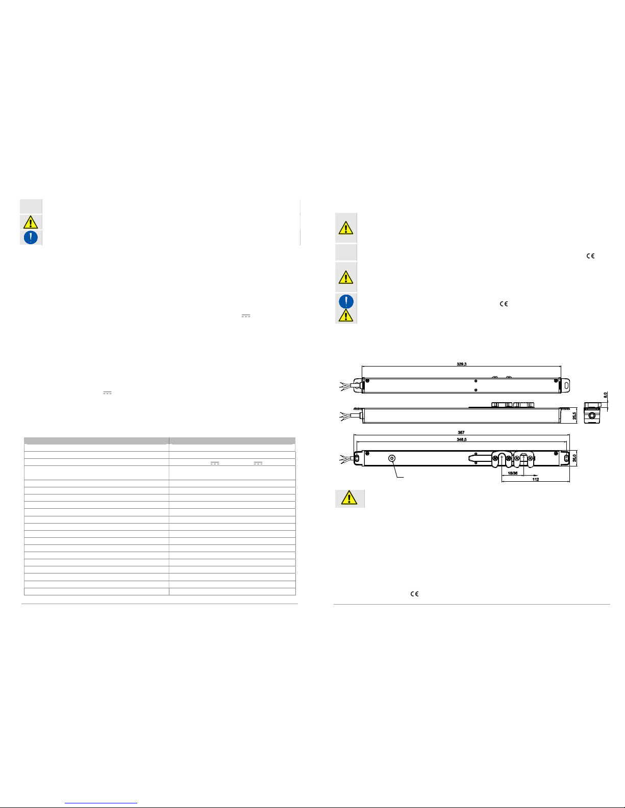
8.2.3 Drilling for external assembly
Determine the drilling points for the linear actuator (the metal one) that corresponds with a
bolt of the sliding accessory to be moved, and mark it with a pencil. The measurements
are provided in the drawing below.
Drill the window frame in the points marked with the diameters indicated in the drawings
and clean the edges of any burr.
Check (by overlapping them) that the actuator is positioned correctly and the hook (in the
closed position) is aligned with the pawl of the closed sliding accessory.
Check that the electrical cable path is free of obstacles; otherwise eliminate them.
Now the window frame can be assembled.
8.2.4 External assembly
Check that the cable path has been prepared beforehand and all the holes have been drilled.
Position the actuator on the window frame and secure it with the screws provided.
Make the electrical connections following the instructions and diagram provided below in
Chapter 9. “Electrical connection”.
Complete the path of the cables and finish making the electrical connections.
Perform a final test and verify that the device operates correctly on the window frame,
moving the pawl of the sliding accessory sideways.
Power the device and move the pawl to the Open position; the hook of the actuator must
slide towards the center of the machine.
Close the sash of the window or door.
The device requires a voltage of 24V .
Higher voltage may destroy the motor.
The device requires a voltage of 24V .
Higher voltage may destroy the motor.

11
9. ELECTRICAL CONNECTION
The device is equipped with power supply cables constructed in compliance with current safety
standards, restrictions for protection against radio interference and according to that required
by standard EN 12101-2 – Smoke and heat exhaust ventilators. Warning if the cables require
extension:
- Use the same type of cable (cable with sheath and core in silicone).
- Prepare the correct cross-section of the cables.
- To avoid connection errors, use the same coloring of the wires.
For wiring and electrical connections see following diagrams:
Connection of a B-LOCK to a chain actuator
Connection of a B-LOCK to more chain actuators
10. START-UP OPERATIONS
- In order to prevent damage, do not apply the 24V power supply voltage to the
system before having performed the start-up.
- Strictly following the work steps below will guarantee a problem-free installation.
10.1. With actuator
The connections between chain actuator and K-LOCK have been made and the
operation has already been bench tested; when opening the K-LOCK opens, goes
to 18 or 36 mm (the hook moves towards the outside of the machine) and then the
chain of the actuator comes out. When closing, first the chain of the actuator re-
enters completely and then the K-LOCK goes to 0 (the hook moves towards the
center of the machine towards the power supply cable).
Caution: First the RESET procedure indicated in the instructions of the INKA
356 actuator should be executed.
Keep the window unhooked from the chain.
If necessary, operate on dip-switch 1 to correct the stroke; (see Chapter 7. “Setting
the dip-switches”).
ACTUATOR
ACTUATOR
ACTUATOR
24V
24V
12
Supply power [24V ] and move the hook into the opening stroke-end position (18
or 36), then cut off the power.
Hook up the window, i.e. check that the hook is inserted in the pawl of the sliding
accessory.
Supply power again and check operation of the assembly, which must be as seen
on the bench.
Repeat the complete cycle a second time.
Now if everything works perfectly, check that all the screws are tightened correctly
and the cables are orderly and well-protected.
10.2. Without actuator (test)
Ensure that the hook is inserted in the pawl of the sliding accessory and can move.
Select dip2=OFF and dip1 according to the desired stroke.
Supply the power supply voltage [24V ]: check the OPEN or CLOSE movement,
depending on the power supply orientation on wire 1. The movement must be
complete up to the stroke-end without obstacles.
11. MAINTENANCE OR CLEANING
In order to guarantee problem-free operation, the following operations must be carried out after
about 1000 opening cycles and at least once a year:
- Check all the screws to ensure that they are tight, except for the two that fix the hook which
must be loosened by ½ turn.
- Check that the wing is seated perfectly in the frame of the window; if necessary, adjust the
fastening.
- Check all parts for damage and wear. If necessary, replace the damaged parts.
12. EMERGENCY OPERATIONS OR MALFUNCTIONS
Strictly follow the instructions provided below.
Observe the safety standards referred to in this booklet.
12.1. Emergency operations
First set dip2 = OFF (free) and power the lock directly, moving the hook to the OPEN stroke-end
(18 or 36 mm).
12.2. Malfunctions of the device
Since the user cannot repair a defective lock safely or correctly, this is not allowed. Repairs
may only be carried out in the factory.
If the device is opened or tampered with, the warranty becomes null and void; therefore it’s
best to replace the device or have it repaired. If the mechanism is stuck, first check to see if
there is a power failure.
If problems arise during installation or operation of the device, it’s advisable to evaluate the
following possible causes of malfunction.
Problem Possible cause Resolution
The device does
not work.
Lack of electricity to the power
supply unit.
Check the presence of electricity
or the state of the automatic
circuit-breaker or safety switch.

13
The power supply unit does not
supply 24V .
Check that the power supply unit
and safety switch are operating
properly.
Connection cable not connected
or has a detached wire.
Check all the electrical
connections.
The device is
powered but does
not respond to
commands.
Probable breakage of an
electronic element or the motor.
Contact a qualified technician or
the manufacturer's service
center.
12.3. LED Light signals
If there are any problems during installation or operation, consult the possible causes listed below:
WITH RED LED
Number of
Flashes
Type of Error Possible Solution
1
Overload error:
The electromechanical lock has
detected an overcurrent in the
motor.
Check that there are no obstacles
preventing it from completing its stroke.
Check that it has been installed correctly.
2
Communication error:
Communication between the
electromechanical lock and
actuators is interrupted.
Check the condition of the connection
cables, and repeat the RESET procedure if
necessary.
3 Error in the actuators Check the error LED on the actuators.
7
Encoder error:
The internal encoder had a
counting error.
Repeat the RESET procedure.
8
Electric power supply error:
The power supply voltage is
outside the allowed range or
unstable.
Check the electrical contacts at the ends of
the lock's cable and ensure that the power
supply voltage is correct.
10
Memory error:
The internal memory write process
failed.
Repeat the RESET procedure.
11
Connection error:
A RESET procedure is being
started with several actuators that
are not compatible with one
another.
Check the type of actuators selected for the
system.
Repeat the RESET procedure.
WITH GREEN LED
LED Status
Meaning
STEADY-ON
Device powered correctly.
The device executed a chain re-entry stroke correctly, completing the
operation by writing to the memory, or is in motion.
FLASHING
Device powered correctly and at the opening stroke-end.
The number of flashes indicates the address number previously
assigned to the device during the RESET procedure.
14
WITH ORANGE LED
LED Status
Meaning
STEADY-ON
Duration < 0.5
seconds
Internal memory write process in progress.
STEADY-ON RESET Procedure in progress.
FLASHING
RESET Procedure finished correctly.
The number of flashes indicates the address assigned to the device in a
configuration with several devices.
13. ENVIRONMENTAL PROTECTION
Respect safety instructions
To disassemble the device from the frame, proceed as for the mounting (see pages from 10 to 13)
in the proper points, in reverse way.
All materials used in the manufacture of this appliance are recyclable.
We recommend that the device itself, and any accessories, packaging, etc. be sent
to a centre for ecological recycling as established from laws in force on recycling.
The device is mainly made from the following materials:
aluminium, zinc, iron, plastic of various type, cuprum,
silicon, silicone.
Dispose materials in conformity with local regulations about removal.
Disassemble the device using suitable tools and separate parts and destine them to disposal or
recycling.
14. CERTIFICATE OF GUARANTEE
The manufacturer will guarantee good function of the appliance. The manufacturer shall
undertake to replace defective parts due to poor quality materials or manufacturing defects in
accordance with article 1490 of the Civil Code.
The guarantee covers products and individual parts for 2 years from the date of purchase. The
latter is valid as long as the purchaser possesses proof of purchase and completion of all
agreed conditions of payment.
Guarantee of good function of appliances agreed by the manufacturer implies that the latter
undertakes to repair or replace free of charge and in the shortest period possible any parts that
break while under warranty.
The purchaser is not entitled to any reimbursement for eventual direct or indirect damage or
other expenses incurred. Attempt to repair by personnel unauthorised by the manufacture shall
render the warranty null and invalid.
The warranty does not cover fragile parts or parts subject to natural wear and tear or corrosion,
overload, however temporary etc. The manufacturer will accept no responsibility for eventual
damage incurred by erroneous assembly, manoeuvre or insertion, excessive stress or inexpert
use.
Repairs performed under guarantee are always "ex factory of the manufacturer". Respective
transport expenses (out/back) are the responsibility of the purchaser.

15
15. DICHIARAZIONE DI INCORPORAZIONE (per una quasi macchina) E
DICHIARAZIONE CE DI CONFORMITÀ / DECLARATION OF
INCORPORATION (for a partly completed machine) AND EC
DECLARATION OF CONFORMITY.
Con la presente il / Hereby the
Costruttore:
Manufacturer:
NEKOS S.r.l.
Via Capitoni 7/5- 36064 Mason Vicentino (Vicenza) - Italy
Tel +39 0424 411011 – Email [email protected]
dichiara sotto la propria responsabilità che i seguenti prodotti
declare under its own responsibility that the following products
Descrizione prodotto :
Product Designation:
Attuatore a cremagliera, lineare a stelo, elettroserratura, tubolare per tende
Rack and pinion drive, linear drive, electromechanical lock, tubular drive
Modello:
Type :
230 V: SKY450
–
SKY 650
NKL 450
24 V: SKY 650
K-LOCK – BK-LOCK
MR28
-
B
Anno di costruzione dal / Year of manufacturing from: 2017
Soddisfano gli applicabili requisiti essenziali della
Direttiva Macchine 2006/42/EC, Allegato I
Fulfil the essential requirements of the Machinery Directive 2006/42/EC, Annex I, Art. 1.1.2, 1.1.3, 1.1.5, 1.2.1,1.2.3,
1.2.6; 1.3.2, 1.3.4, 1.3.9, 1.5.1, 1.5.2, 1.5.6, 1.5.7, 1.5.8, 1.5.9, 1.5.10, 1.5.11, 1.7.1, 1.7.1.1, 1.7.3, 1.7.4.2, 1.7.4.3
La documentazione tecnica pertinente è compilata secondo l’Allegato VII, sezione B
The relevant technical documentation is compiled in accordance with Annex VII, Part B
La persona autorizzata a costituire la documentazione tecnica pertinente è:
The person authorised to compile the relevant technical documentation is: ing. Matteo Stefani – Nekos S.r.l.
Su richiesta adeguatamente motivata delle autorità nazionali, la documentazione tecnica dei citati prodotti sarà resa
disponibile, via e-mail, entro un tempo compatibile con la sua importanza.
In response to a reasoned request by the national authorities, we will provide, via e-mail, the relevant information on the
product listed above within an adequate period proportional to its importance.
Inoltre i succitati prodotti sono conformi alle disposizioni pertinenti delle seguenti Direttive:
Furthermore the products listed above complies with the provisions of followings Directives :
2014/30/EU Direttiva Compatibilità Elettromagnetica / ElectroMagnetic Compatibility Directive (EMCD)
2014/35/EU Direttiva Bassa Tensione / Low Voltage Directive (LVD)
2011/65/EU Direttiva sulla restrizione dell’uso di determinate sostanze pericolose nelle apparecchiature elettriche
ed elettroniche (Direttiva RoHS) / Restriction of the use of certain hazardous substances Directive (RoHS Directive)
e delle seguenti norme armonizzate e/o specifiche tecniche:
and of the following harmonised standards and/or technical specifications:
EN 60335
-
2
-
103;
EN 61000
-
6
-
3:2007 + A1:2011;
EN 61000
-
6
-
2:2005 + AC:2005
EN 60335-1:2012 + EN 60335-1/A11:2014; EN 50581:2012;
La messa in moto di una macchina completa che includa la quasi macchina sopra menzionata, da noi fornita, non è
permessa finché non sia accertato che l’installazione sia stata fatta secondo le specifiche e le indicazioni di installazione
contenute nel “Manuale d’istruzioni” fornito con la quasi-macchina, e che sia stata espletata e documentata, in apposito
protocollo, una procedura di accettazione da parte di un tecnico abilitato.
Commissioning of the complete machinery including the above mentioned drives delivered by us is not allowed until it is
ascertained that the installation of the complete machinery was performed in accordance with the specifications and the
operating and installation advice given in our Mounting Instructions, and that the acceptance procedure was duly carried out
and documented in an acceptance protocol by a specialist.
Questa dichiarazione è fatta dal costruttore / This is declared by the manufacturer :
NEKOS S.r.l. - Via Capitoni 7/5- 36064 Mason Vicentino (Vicenza) - Italy
Rappresentato da / Represented by :
Giuliano Galliazzo – A.D. Presidente / President CEO
Firma / Valid signature
Luogo e data / Place and date: Mason Vicentino 28/07/2017
16
NEKOS S.r.l.
I - 36064 - MASON VICENTINO (VI) - Via Capitoni, 7/5
Telefono (+39) 0424 411011 Fax (+39) 0424 411013
[email protected] - http://www.nekos.it
Table of contents
Other nekos Lock manuals
Popular Lock manuals by other brands

Assa Abloy
Assa Abloy Yale Real Living Assure Lock YRC216 Installation and programming instructions

BSi
BSi R3-R8D Installation, Programming, Use

Yale
Yale Real Living Assure Lock Installation and programming instructions

AMSEC
AMSEC ESL15 operating instructions

Alarm Lock
Alarm Lock DL2700-SERIES Programming instructions

Dorcas
Dorcas DUO 25/85 manual

Lockly
Lockly SECURE installation manual

COMPX
COMPX MFW 23168 Dimensional drawing

CEStronics
CEStronics Omega Active Programming instructions

Pro-4 Tactical
Pro-4 Tactical Secure Touch Lock instruction manual

Rittal
Rittal CMC III Assembly and operating instructions

Austral Lock
Austral Lock gain&lorough YARRA HORIZON quick start guide