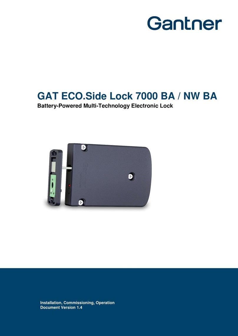
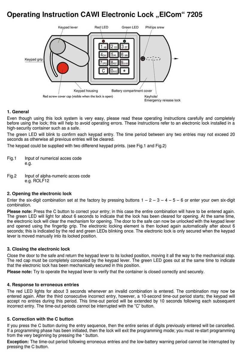
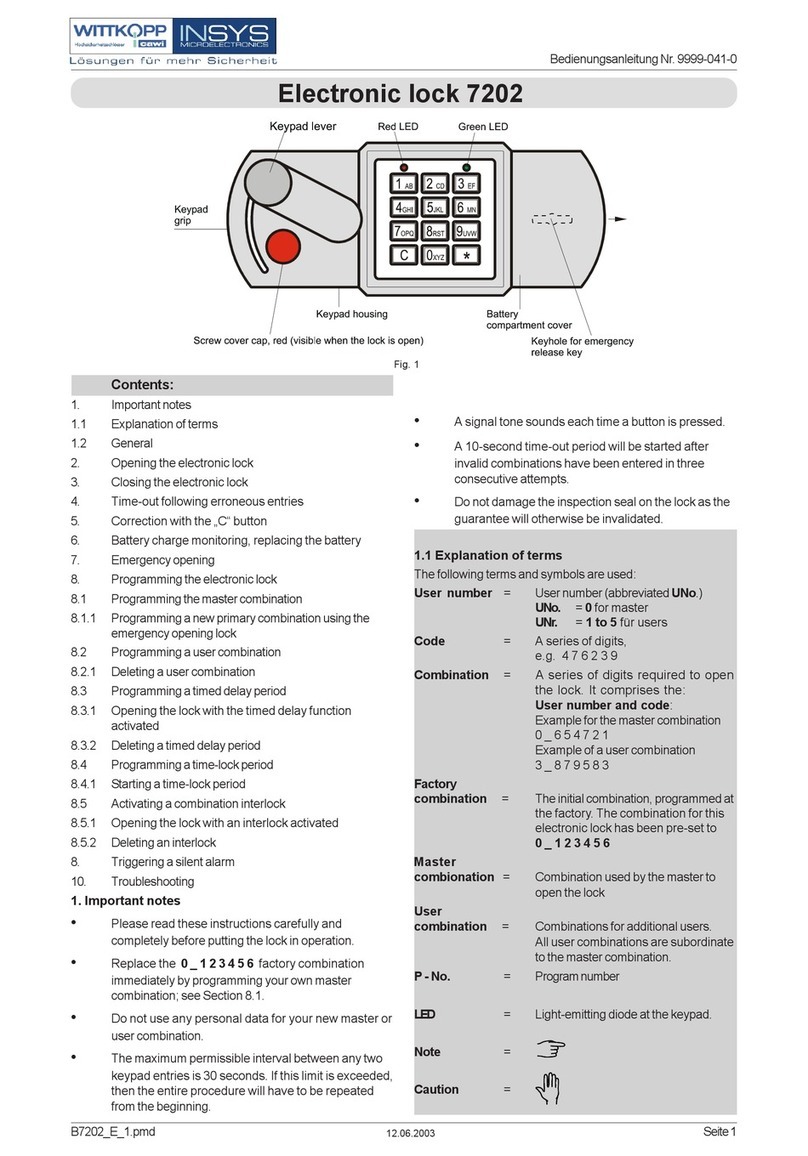
Gantner GAT ECO.Side Lock 7000 User manual

Functional description
Lockers can be electronically locked and unlocked by the GAT ECO.Side Lock
7000. The user simply presses the locker door shut and holds their data
carrier next to the RFID reading center on the locker door. The lock reads
the data on the data carrier and verifies the information. Following valid
authorization, the locker door is then locked or unlocked accordingly by
the GAT ECO.Side Lock 7000.
Locking and unlocking actions are signaled by an integrated beeper and
a bi-colored LED.
The GAT ECO.Side Lock 7000 can be configured via USB, and also on-
site using the programming data carrier, to operate in different modes.
Highlights
•Maintenance-free “Low-Power Technology” provides a useful life of
approximately 10 years without battery replacement
•Free and personal locker mode selection
•Rental locker function
•Selectable operation mode
•Similar hardware to the GAT NET.Lock 7000 locks allows easy
exchange between both lock types
•Suitable for left and right hinged doors and a variety of locker material
•Internal memory records the last 150 locker actions
•Reliable data transmission between RFID reader and data carrier
•Motor driven locking/unlocking guarantees exceptional reliability
•Locking status indicated via LED and beeper
•Configuration via a PC/laptop (USB connection)
•Vandal-proof installation
•Integrated break-in alarm
GAT ECO.Side Lock 7000
Battery Powered MIFARE® and ISO 15693 Lock
Application
The GAT ECO.Side Lock 7000 is the ideal solution for the convenient
electronic locking of wardrobe lockers in fitness clubs, attraction parks,
golf resorts and individual business applications such as filing cabinets and
safe deposit boxes. Identification of system users by the lock is performed
using contactless RFID data carriers (Radio Frequency Identification).
Different types of data carrier media such as chip cards, chip bands and
key tags are available.
The GAT ECO.Side Lock 7000 is suitable for any kind of locker material
(wood, HPL, glass, steel sheet and fully synthetic materials) and can be
used with both left and right handed opening doors. The various operating
modes provide flexibility and allow the locks to be configured to suit
specific system requirements.
Due to the mechanical compatibility with the GAT NET.Lock 7000 series a
quick and simple installation of existing locker rooms using the GAT ECO.
Side Lock 7000 is possible.
Description Part No.
GAT ECO.Side Lock 7000
Battery operated locker lock for MIFARE®and ISO 15693
data carriers, without batteries, without bolt set, without
door label
631325
1
www.gantner.com
Order information
Description Part No.
Manual GAT ECO.Side Lock 7000
Operating and installation instructions in English
932329
GAT NET.Lock BoltSet 7100
Door shackle carrier and booster for non-metallic doors
369535
GAT NET.Lock BoltSet 7200
Door shackle carrier and booster for metallic doors
532123
GAT NET.Lock BoltSet 7300
Door shackle carrier and booster for glass doors (adhesive
not included)
774232
Batterie 3,6V Lithium LS14500
Battery for GAT ECO.Side Lock 7000
912012
GAT ECO.Side Lock Basic Set F/ISO
Package with configuration software, USB cable for PC
connection, 3 master data carriers, 4 system data carriers
812528
GAT Key Tag 7309, S50 MASTER
Master data carrier for the GAT ECO.Side Lock 7000
816229
GAT NET.Lock Label GEA right
GAT NET.Lock Label GEA NUM right
Self-adhesive door label in GANTNER design, for right-
hinged doors, with or without locker number
679034
679236
GAT NET.Lock Label GEA left
GAT NET.Lock Label GEA NUM left
Self-adhesive door label in GANTNER design, for left-
hinged doors, with or without locker number
370022
679135
Accessories
Valid from June 10th, 2015 • Technical data subject to modification without notice!
DB_GAT-ECOSide-Lock7000--EN_11.indd • Part No. 642832
GAT ECO.Side Lock 7000
GAT NET.Lock BoltSet 7100
Power supply: 2 x 3.6 V Lithium battery, type AA,
SAFT - LS14500
Battery life-time: Up to 10 years at +20 °C (68 °F)
Data storage: EEPROM for 150 bookings, data
preservation during battery change
Internal clock: Quartz-controlled real time clock
Reader type: - MIFARE®, supported types:
Classic (1k and 4k), Ultralight®
DESFire EV1®
(approval of the data carrier types to
be used for the specific application
required - approval by GANTNER)
- ISO 15693
Frequency of reading field: 13.56 MHz
Range of reading field: Approx. 5 to 35 mm (0.2´´ to 1.38´´),
depending on the installation and
data carrier
Break-open resistance capab.: DIN 4547-2 class C
Display element: LED (red/green)
Configuration interface: USB 2.0, Micro-B
Housing material: Plastic (PC), halogen-free, V0
Housing color: dark gray
Dimensions: 125.2 mm x 100 mm x 25 mm
(4.93´´ x 3.94´´ x 0.98´´)
Permitted ambient temperature: 0 to +60 °C (32 °F to 140 °F)
Protection type: IP 52
Protection class: III
Weight: Approx. 400 g (14.1 oz)
Environment class
based on VdS 2110: II (conditions in indoor areas)
2www.gantner.com
Technical data
Typical application
Row of lockers
GAT ECO.Side Lock 7000
Data carriers
Front label
Bolt Set (inside the locker door)
Valid from June 10th, 2015 • Technical data subject to modification without notice!
DB_GAT-ECOSide-Lock7000--EN_11.indd • Part No. 642832
GAT ECO.Side Lock 7000 GAT NET.Lock BoltSet 7100
31.3 mm (1.23”)
88.1 mm (3.47”)
1
4
4
5
4
1
25.0 mm (0.98”)
100.0 mm (3.94”)
50.0 mm (1.97”)
94.0 mm (3.7”)
6.0 mm (0.24”)
125.2 mm (4.93”)
91.0 mm (3.58”)
17.0 mm (0.67”)
7
6
Top View
Side View
Front View
8.5 mm
(0.33”)
2
2
2
31.3 mm (1.23”)
88.1 mm (3.47”)
1
4
4
5
4
1
25.0 mm (0.98”)
100.0 mm (3.94”)
50.0 mm (1.97”)
94.0 mm (3.7”)
6.0 mm (0.24”)
125.2 mm (4.93”)
91.0 mm (3.58”)
17.0 mm (0.67”)
7
6
Top View
Side View
Front View
8.5 mm
(0.33”)
2
2
2
40.3 mm (1.58”)
88.1 mm (3.47”)
1
4
4
5
4
1
2
25.0 mm (0.98”)
100.0 mm (3.94”)
50.0 mm (1.97”)
94.0 mm (3.7”)
6.0 mm (0.24”)
125.2 mm (4.93”)
91.0 mm (3.58”)
17.0 mm (0.67”)
7
6
2
2
Top View
Side View Front View
8 mm
(0.31”)
Side View
Top View
GAT NET.Lock BoltSet 7200
78.0 mm (3.07”)
104.5 mm (4.11”)
61.8 mm (2.43”)
Top View
Side View Front View
88.1 mm (3.47”)
7
7
6
3
8
4
4
5
3
3
8
8
1
1
10 mm
(0.39”)
78.0 mm (3.07”)
104.5 mm (4.11”)
61.8 mm (2.43”)
Top View
Side View
Front View
88.1 mm (3.47”)
7
7
6
3
8
4
4
5
3
3
8
8
10 mm
(0.39”)
1
1
Side View
Top View
78.0 mm (3.07”)
104.5 mm (4.11”)
61.8 mm (2.43”)
Top View
Side View Front View
88.1 mm (3.47”)
7
7
6
3
8
4
4
5
3
3
8
8
1
1
10 mm
(0.39”)
78.0 mm (3.07”)
104.5 mm (4.11”)
61.8 mm (2.43”)
Top View
Side View
Front View
88.1 mm (3.47”)
7
7
6
3
8
4
4
5
3
3
8
8
1
1
10 mm
(0.39”)
78.0 mm (3.07”)
104.5 mm (4.11”)
61.8 mm (2.43”)
Top View
Side View Front View
88.1 mm (3.47”)
7
7
6
3
8
4
4
5
3
3
8
8
1
1
10 mm
(0.39”)
GAT NET.Lock BoltSet 7300
4
Top View
Side View Front View
4
4
5
2
9
2
9
7
6
2
9
88.1 mm (3.47”)
40.3 mm (1.58”)
8 mm
(0.31”)
3 mm
(0.12”)
1
1
Side View
Top View
4
Top View
Side View
Front View
4
4
5
2
9
2
9
7
6
2
9
88.1 mm (3.47”)
40.3 mm (1.58”)
8 mm
(0.31”)
3 mm
(0.12”)
1
1
Side View
Top View
4
Top View
Side View
Front View
4
4
5
2
9
2
9
7
6
2
9
88.1 mm (3.47”)
40.3 mm (1.58”)
8 mm
(0.31”)
3 mm
(0.12”)
1
1
Side View
Top View
Dimensions
1. GAT ECO.Side Lock 7000
2. GAT NET.Lock Bolt Set 7100 (for non-metal doors)
3. GAT NET.Lock Bolt Set 7200 (for metal doors)
4. Door shackle
5. Door contact
6. Booster
7. Hole for status LED
8. Label Carrier
9. Metal support (for glass doors)
40.3 mm (1.58”)
88.1 mm (3.47”)
1
4
4
5
4
1
2
25.0 mm (0.98”)
100.0 mm (3.94”)
50.0 mm (1.97”)
94.0 mm (3.7”)
6.0 mm (0.24”)
125.2 mm (4.93”)
91.0 mm (3.58”)
17.0 mm (0.67”)
7
6
2
2
Top View
Side View Front View
8 mm
(0.31”)
Side View
Top View
31.3 mm (1.23”)
88.1 mm (3.47”)
1
4
4
5
4
1
25.0 mm (0.98”)
100.0 mm (3.94”)
50.0 mm (1.97”)
94.0 mm (3.7”)
6.0 mm (0.24”)
125.2 mm (4.93”)
91.0 mm (3.58”)
17.0 mm (0.67”)
7
6
Top View
Side View Front View
8.5 mm
(0.33”)
2
2
2

4. Drill three mounting holes (6) for the GAT NET.Lock Bolt Set 7100.
5. Drill a hole for the status LED in the locker door (7). The recommended
hole diameter is 10 mm.
6. Mount the bolt set onto the locker door using three screws.
Attention: Use the correct screws according to the type of locker
material, max. Ø 4 mm (0.16´´). The maximum allowed
tightening torque of the screws is 2 Nm (1.47 lb-ft).
7. A label (GANTNER standard design or custom design) can be
attached to the locker front. If a custom label design is used, ensure
that a transparent field for the LED light is included in the label design.
8. Test the locker door to confirm that it can close easily and the door
shackle inserts correctly into the GAT ECO.Side Lock 7000.
3
www.gantner.com
Valid from June 10th, 2015 • Technical data subject to modification without notice!
DB_GAT-ECOSide-Lock7000--EN_11.indd • Part No. 642832
Installation Instructions
The GAT ECO.Side Lock 7000 is mounted on the inside of the locker wall
using 3 screws. The bolt set including door shackle is attached to the inner
side of the locker door. For non-metallic doors, only a drill hole through the
locker door is required for the status LED. For metallic doors, a cut-out
must be made in the locker door to accommodate the bolt set and label
carrier. For glass doors, the metal support is attached to the locker door
using adhesive.
Note: The GAT ECO.Side Lock 7000 needs min. 10 mm clearance from
the bottom or top of the locker to allow the hole marking gauge to
be used for installation.
Door status contact
The GAT ECO.Side Lock 7000 has a contact that is activated or deactivated
by the door contact (5) on the bolt set when the locker door is closed or
opened respectively. This function determines the open/close state of the
door. It is important that this contact remains clean and undamaged to
ensure the correct functionality of the GAT ECO.Side Lock 7000.
Door width
The minimum allowed door width (measured from the door shackle to the
hinge) is 230 mm (9.05´´). If the door is narrower than this measurement,
the door shackle will hit the locker when the door is being closed.
50 mm (1.9´´)
6 mm (0.24´´)
94 mm (3.7´´)
Locker door
6
6
74 mm (2.91´´)
17 mm
(0.67´´)
14.6 mm (0.57´´)
17.6 mm (0.69´´)
16.4 mm
(0.64´´)
1
2
8 mm
(0.31´´)
43.4 mm
(1.71´´)
32 mm
(1.26´´)
1
6
6
7
7
5
15 mm (0.59´´)
Locker wall
2
3
3
3
3
3
3
Locker door
Centre of hinge rotation
min. 230 mm (9.05´´)
Locker wall
Locker wall
Installation requirements for GAT ECO.Side Lock 7000 and bolt set
Please pay particular attention to the following points:
- When the locker door is pressed shut, ensure there is no gap between
the bolt set (2) and the front of the GAT ECO.Side Lock 7000. Ideally
the bolt set should touch the front of the lock.
- The front side of the bolt set and the GAT ECO.Side Lock 7000 must be
aligned parallel to each other.
Installation procedure
Note: Before installing all locks in a new locker system, a test installation
of at least one lock and a final function check must be performed.
Only once the functional testing is successfully completed may the
remaining locks be installed in the same way.
1. Drill three holes (3) for the GAT ECO.Side Lock 7000 into the locker
wall.
2. Insert the batteries into the GAT ECO.Side Lock 7000 (see page 7).
3. Mount the GAT ECO.Side Lock 7000 with three screws (3) on the
inside locker wall.
Attention: Use the correct screws according to the type of locker
material, max. Ø 4 mm (0.16´´). The maximum allowed
tightening torque of the screws is 2 Nm (1.47 lb-ft).
Mounting on Non-Metallic Doors
1. GAT ECO.Side Lock 7000
2. GAT NET.Lock Bolt Set 7100
3. Mounting screws for the
GAT ECO.Side Lock 7000
5. Door contact
6. Mounting screws for bolt set
7. LED (hole in locker door)

4www.gantner.com
Valid from June 10th, 2015 • Technical data subject to modification without notice!
DB_GAT-ECOSide-Lock7000--EN_11.indd • Part No. 642832
Mounting on Metallic Doors
Cut-outs in the locker door
Cut-outs must be made in the inside and outside walls of the locker
door to mount the GAT NET.Lock Bolt Set 7200 and label carrier. The
installation procedure is described on the next page. The measurements
for the cut-outs are shown in the diagram below.
2
2
6
7
1
6
9
6
6
10
7
123
11
7
5
1
Locker wall
50 mm (1.9´´)
6 mm (0.24´´)
94 mm (3.7´´)
Locker door (outside wall)
Locker door (inside wall)
74 mm (2.91´´)
17 mm (0.67´´)
min. 18 mm (0.71´´)
max. 26 mm (1.02´´)
Inside of locker Locker door
(Front view without label carrier)
Locker door
(Front view with label carrier)
15.1 mm (0.59´´)
32.6 mm
(1.28´´)
Locker wall
Locker door
(Front view with label carrier)
Locker wall
3
3
17.4 mm
(0.68´´)
33
3
3
9
8
9
LED
6
8
6
LED position
Cut-out on outside wall
Cut-out on inside wall
Locker door (outside wall)
Locker door (inside wall)
Inside of locker
Locker wall
Locker door (outer wall)
Cut-out area marked in grey 4 x holes for screws,
Ø 3.6 mm (0.14´´)
Locker door (inner wall)
Cut-out area marked in grey
30.4 mm
(1.2´´)
63.1 mm
(2.48´´)
67.6 mm (2.66´´)
16.8 mm (0.66´´)
29.1 mm
(1.14´´)
38.9 mm
(1.53´´)
43.4 mm
(1.71´´)
33.6 mm
(1.32´´)
62.6 mm (2.46´´)
29 mm
(1.14´´)
16.8 mm
(0.66´´)
19.3 mm
(0.76´´)
1. GAT ECO.Side Lock 7000
2. GAT NET.Lock Bolt Set 7200
3. Mounting screws for GAT ECO.Side Lock 7000
5. Door contact
6. Mounting screws for bolt set
7. LED position
8. Cut-out for GAT NET.Lock BoltSet 7200
9. Cut-out for label carrier
10. Label carrier

5
www.gantner.com
Valid from June 10th, 2015 • Technical data subject to modification without notice!
DB_GAT-ECOSide-Lock7000--EN_11.indd • Part No. 642832
9. Attach the front label (11) onto the label carrier.
Attention: If a custom label design is used, ensure that a transparent
field for the status LED (7) is included in the label design.
10. Test the locker door to confirm that it can close easily and the door
shackle inserts correctly into the GAT ECO.Side Lock 7000.
2
2
6
7
1
6
9
6
6
10
7
123
11
7
5
1
Locker wall
50 mm (1.9´´)
6 mm (0.24´´)
94 mm (3.7´´)
Locker door (outside wall)
Locker door (inside wall)
74 mm (2.91´´)
17 mm (0.67´´)
min. 18 mm (0.71´´)
max. 26 mm (1.02´´)
Inside of locker Locker door
(Front view without label carrier)
Locker door
(Front view with label carrier)
15.1 mm (0.59´´)
32.6 mm
(1.28´´)
Locker wall
Locker door
(Front view with label carrier)
Locker wall
3
3
17.4 mm
(0.68´´)
33
3
3
Installation requirements for GAT ECO.Side Lock 7000 and bolt set
Please pay particular attention to the following points:
- The thickness of the locker door must be between 18 and 26 mm
(0.71´´ and 1.02´´).
- When the locker door is pressed shut, ensure there is no gap between
the bolt set (2) and the front of the GAT ECO.Side Lock 7000. Ideally
the bolt set should touch the front of the lock.
- The front side of the bolt set and the GAT ECO.Side Lock 7000 must be
aligned parallel to each other.
Installation procedure
Note: Before installing all locks in a new locker system, a test installation
of at least one lock and a final function check must be performed.
Only once the functional testing is successfully completed may the
remaining locks be installed in the same way.
1. Drill 3 holes (3) for the GAT ECO.Side Lock 7000 into the locker wall.
2. Insert the batteries into the GAT ECO.Side Lock 7000 (see page 7).
3. Mount the GAT ECO.Side Lock 7000 with 3 screws (3) on the inside
locker wall.
Attention: Use the correct screws according to the type of locker
material, max. Ø 4 mm (0.16´´). The maximum allowed
tightening torque of the screws is 2 Nm (1.47 lb-ft).
4. Cut-out a section, 62.6 mm x 68 mm (2.46´´ x 2.68´´), in the inner wall
of the locker door for the GAT NET.Lock Bolt Set 7200.
5. Drill 4 holes (6) in the inner wall of the locker door for mounting the
GAT NET.Lock Bolt Set 7200.
6. Cut-out a section, 67.6 mm x 93.6 mm (2.66´´ x 3.68´´), in the outer
wall of the locker door for the label carrier.
7. Mount the bolt set onto the inside wall of the locker door using 4
screws.
Attention: Use pan-head metal screws, Ø 3.5 mm (0.14´´), screw
length depends on locker door thickness. The maximum
tightening torque of the screws is 2 Nm (1.47 lb-ft).
8. Push the label carrier onto the outside wall of the locker door. The
label carrier will hold in place with the lashes on the label carrier. To
protect against manipulation, a screw can be used to fix the bolt set to
the label carrier.
Attention: Use a countersunk screw, Ø 2.9 mm (0.11´´). Screw length
depends on locker door thickness, e.g., a 15 mm (0.59´´)
thick door requires a 19 mm (0.75´´) long screw.

6www.gantner.com
Valid from June 10th, 2015 • Technical data subject to modification without notice!
DB_GAT-ECOSide-Lock7000--EN_11.indd • Part No. 642832
Mounting on Glass Doors
3
3
1
7
5
50 mm (1.9´´)
6 mm (0.24´´)
94 mm (3.7´´)
Locker door (glass)
74 mm (2.91´´)
17 mm
(0.67´´)
14.6 mm (0.57´´)
11 mm
(0.43´´)
49.4 mm
(1.94´´)
38.6 mm
(1.52´´)
212
12
7
2
Locker wall
17.6 mm (0.69´´)
16.4 mm
(0.64´´)
1
3
3
3
3
Installation procedure
Note: Before installing all locks in a new locker system, a test installation
of at least one lock and a final function check must be performed.
Only once the functional testing is successfully completed may the
remaining locks be installed in the same way.
1. Drill 3 holes (3) for the GAT ECO.Side Lock 7000 into the locker wall.
2. Insert the batteries into the GAT ECO.Side Lock 7000 (see page 7).
3. Mount the GAT ECO.Side Lock 7000 with 3 screws (3) on the inside
locker wall.
Attention: Use the correct screws according to the type of locker
material, max. Ø 4 mm (0.16´´). The maximum allowed
tightening torque of the screws is 2 Nm (1.47 lb-ft).
4. Use adhesive to attach the GAT NET.Lock BoltSet 7300 in the correct
position to the inside of the locker door. Ensure the bolt set and metal
support are screwed together before applying adhesive. GANTNER
Electronic GmbH has successfully tested the following adhesives:
For transparent glass doors:
Conloc UV 680 from EGO. Only suitable for transparent glass doors
without color-coating as this adhesive requires exposure to UV light
(i.e., daylight) to cure.
For non-transparent glass doors:
Conloc UV 683 and Conloc Aktivator 953 from EGO. This combination
does not require UV light to cure and is also suitable for opaque glass
doors (e.g., with painted or color-coated tint treatment).
Attention: If comparable adhesives are to be used, test to ensure the
adhesive meets the strength requirements. Always follow
the adhesive manufacturer’s instructions.
5. A label (GANTNER standard design or custom design) can be
attached to the locker front. If a custom label design is used, ensure
that a transparent field for the LED light is included in the label design.
6. Test the locker door to confirm that it can close easily and the door
shackle inserts correctly into the GAT ECO.Side Lock 7000.
1. GAT ECO.Side Lock 7000
2. GAT NET.Lock Bolt Set 7300
3. 3 x mounting screws for the
GAT ECO.Side Lock 7000
5. Door contact
7. LED position
12. Metal support for glass door (included
in the GAT NET.Lock BoltSet 7300)
Installation requirements for GAT ECO.Side Lock 7000 and bolt set
Please pay particular attention to the following points:
- When the locker door is pressed shut, ensure there is no gap between
the bolt set (2) and the front of the GAT ECO.Side Lock 7000. Ideally
the bolt set should touch the front of the lock.
- The front side of the bolt set and the GAT ECO.Side Lock 7000 must be
aligned parallel to each other.

Inserting the battery:
1. Ensure battery polarity is the same as shown in the diagram above.
2. Press the battery down into the compartment until it locks into place.
3. Reinstall the battery cover over the battery compartment and push down
until the battery cover is level with the surrounding GAT ECO.Side Lock
7000 housing.
Insert the batteries directly before the GAT ECO.Side Lock 7000 is
mounted to avoid unnecessary battery usage.
Only use the approved battery listed in the “Accessories” section
on page 1 (2 x Batterie 3,6V Lithium SAFT - LS14500, Part No.
912012). Safety instructions
- This device must be installed by qualified personnel only.
- The applicable safety and accident prevention regulations
must be observed.
- Safety devices must not be removed.
- Please observe the technical data of the device specified
on the data sheet.
Set-up and configuration
Power supply
The unit is powered by two 3.6 V AA Lithium SAFT - LS14500 batteries
(see technical data). In order to access the battery compartment of the
GAT ECO.Side Lock 7000, the red battery cover (1 in diagram below) on
the underside of the housing must be removed.
The WEEE symbol on GANTNER products and their packaging
indicates that the corresponding material must not be disposed
of with normal household waste. Instead such marked waste
equipment must be disposed of by handing it over to a designated
electronic waste recycling facility. Separating and recycling this
waste equipment at the time of disposal will help to conserve
natural resources and ensure that it is recycled in a manner that
protects human health and the environment. Please contact your
local authority for further details of your nearest electronic waste
recycling facility.
7
www.gantner.com
Valid from June 10th, 2015 • Technical data subject to modification without notice!
DB_GAT-ECOSide-Lock7000--EN_11.indd • Part No. 642832
Configuration
The configuration settings of the GAT ECO.Side Lock 7000 can be adjusted
using a PC/laptop and GAT Config Manager configuration software.
A Micro-B USB port is provided on the side of the GAT ECO.Side Lock
7000 for computer connectivity.
1. Connect the USB cable to the GAT ECO.Side Lock 7000 (1).
2. Connect the other end of the USB cable to the USB port of a PC/
laptop
3. Hold the service data carrier next to the reading field to activate
configuration mode (2).
1
The USB cable, service data carrier and configuration software are
included in the GAT ECO.Side Lock Basic Set F/ISO (Part No. 812528).
A detailed description of the configuration settings and how to configure
the GAT ECO.Side Lock 7000 can be found in the manual.
SERVICE
1
2
This manual suits for next models
1
Table of contents
Other Gantner Lock manuals

Gantner
Gantner GAT ECO.Side Lock 7000 BA Guide

Gantner
Gantner GAT Lock 6010 B User manual

Gantner
Gantner GAT SMART.Lock 7000 System Quick guide

Gantner
Gantner GAT Lock 6010 F User manual

Gantner
Gantner GAT NET.Lock 7020 System Quick guide

Gantner
Gantner GAT ECO.Side Lock 7010 F/ISO Quick guide

Gantner
Gantner Mifare Gat ECO.Lock 7 F/ISO Series Quick guide
Popular Lock manuals by other brands

SECO-LARM
SECO-LARM Enforcer E-941SA-80Q installation manual

Schlage
Schlage CO-100 installation instructions

SECO-LARM
SECO-LARM E-941SA-1K2PD installation manual

Sargent
Sargent Assa Abloy 9900 installation instructions

Hama
Hama 00086516 operating instructions

Trilock
Trilock Contemporary installation instructions