Nemalux MR3 User manual

MR3 & MR6 Luminaires are suitable for use in the following areas as dened by the National
Electrical Code (NEC) and the Canadian Electrical Code (CEC):
Certied to: UL 1598, UL 1598A and UL 8750
CSA C22.2 NO. 250.0 and CSA C22.2 NO 250.13;
MR3 & MR6 luminaires are designed for use indoors, outdoors, wet locations, and areas containing
moisture, dirt, corrosion, vibration, and rough usage. The MR luminaire is also certied for use as a
marine, outside type (saltwater) non-recessed luminaire.
Housing: Copper-free Cast Aluminium with Polycarbonate lens
Voltage: AC: 120-277 VAC | HV: 347: 347 VAC 50/60Hz
Rated Current: MR3: 0.25A@120 VAC | 0.10A@347 VAC
MR6: 0.50A@120 VAC | 0.20A@347 VAC
Connections: 3/4” NPT Conduit | Black: Line | White: Neutral | Green: Ground
All eld wiring supply conductors shall be rated 90°C minimum and rated for
supply voltage (300V AC Models, 600V HV models). Class 1 Wiring Only.
Temperature Range: -40° C to +55° C
Ingress Protection: IP66 and IP67 rated for surface/suspension mount, yoke mount, pendant hook,
and conduit connected installations only. | Suitable For Wet Locations. Marine
Outside Type (Salt Water).
APPLICATION
TM
Nemalux
I N DUSTRIAL
MR-GEN
rev. A-15
1-4
MADE IN CANADA
INSTALLATION INSTRUCTIONS
E477827
E477827
STEP 1:
Inspect shipping package and contents to
ensure no damage has occurred during
shipping.
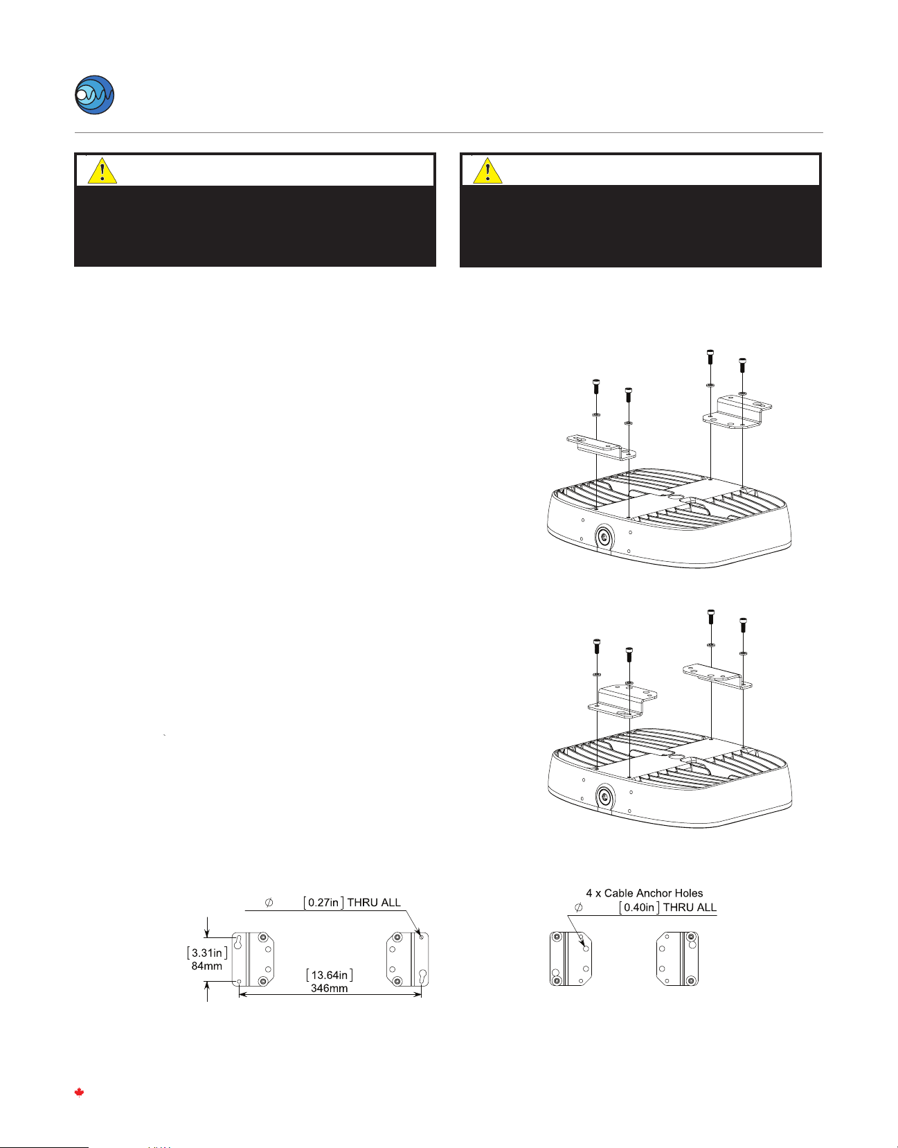
STEP 2:
Install included Surface/Suspension Mount
Brackets. See diagram for orientation of
brackets for each version.
Install with included M6 bolts and washers to
7 N-m (62 in-lbs).
STEP 3:
- For surface mounting conguration, mount
xture to desired locations with 4x 1/4-20 OR
M6 Screws or Bolts.
- For suspension mounting conguration,
connect 4x anchors to points shown
2 x
7mm
10mm
SURFACE MOUNTING CONFIGURATION
SUSPENSION MOUNTING CONFIGURATION
SURFACE MOUNTING CONFIGURATION SUSPENSION MOUNTING CONFIGURATION
TM
Nemalux
I N DUSTRIAL
MR-GEN
rev. A-15
2-4
MADE IN CANADA
INSTALLATION INSTRUCTIONS
(Brackets are Ordered Separately)
Refer to alternate instructions if using Wall, Pole, Yoke, Conduit or Hook Mount
WARNING
To reduce the risk of electric shock, disconnect the luminaire
from the supply circuit before opening for installation and
servicing. Keep tightly closed when in operation.
WARNING
To avoid the risk of re, explosion, or electric shock, this
product should be installed, inspected, and maintained
by a qualied electrician only, in accordance with all
applicable electrical codes.
MR-SM – SURFACE MOUNT INSTALLATION
Ordered Separately

STEP 4:
To begin wiring, remove power supply lid by
loosening six (6) M4 captive screws using a 3mm hex
driver.
Allow the captive fasteners to remain in the lid for
ease of re-installation.
The lid is secured with a retention cable.
STEP 5:
Supply connection to be made through one of 3
3/4-14 NPT entries on the luminaire. If using
Surface, Suspension or Yoke conguration, install
appropriate Listed 3/4” NPT cable gland for cable
size and be sure to follow all applicable local
electrical codes for the specic hazardous locations.
Torque cable gland base to manufacturer's
recommended specication. All unused entries
must be plugged with a NPT plug (two provided).
OR
Install Direct Rigid Conduit as per local electrical
code. For direct rigid conduit installation, torque
hand tight plus 2 to 3 turns
NOTE:
To aid in assembly and protection against ingress
use of a petrolatum or soap thickened mineral oil
based thread lubricant/sealant is necessary.
STEP 6:
Feed wire into Power Supply cavity.
Strip 100mm (4”) of cable casing and strip
conductors 8mm (0.32”).
NOTE:
If using cable, terminate the supply end in a suitable
Listed metal junction box using a suitable Listed
tting approved for installation location as required.
All eld wiring supply conductors shall be rated 90°C
minimum and rated for supply voltage (300V AC
Models, 600V HV models).
4”
100mm
0.32”
8 mm
TM
Nemalux
I N DUSTRIAL
MR-GEN
rev. A-15
3-4
MADE IN CANADA

STEP 7:
Make wiring connections from branch circuit
conductors to factory provided lead wires. Refer to
NEC/CEC codes and follow all applicable local
standards.
The MR luminaire is suitable for daisy-chain wiring of
multiple luminaires on a single circuit. Input supply
wiring through one NPT hub as described in Step 5
above. Feed input wiring into the luminaire and
connect to LED driver supply wires using the wiring
connectors provided. Connect output wiring using the
same wiring connectors. Feed output wiring through
the remaining NPT hub as described in Step 5 above.
For dimming, connect 18AWG or larger conductors to
dimming connection points.
STEP 8:
Close Power Supply Cavity Lid.
A. Re-install the power supply lid using six (6)
Captive M4 screws.
B. Tighten M4 Captive screws to 2 Nm (17in-lbs)
Line - Black
Neutral - White
Ground - Green
Red (+)
Blue ( - )
Violet (+)
Grey (-) 0-10V
Dimming
Control
LED
Module
LED
Driver
TM
Nemalux
I N DUSTRIAL
MR-GEN
rev. A-15
4-4
MADE IN CANADA

STEP 1:
Inspect shipping package and contents to
ensure no damage has occurred during
shipping.
STEP 2:
Install the provided plastic 3/4”bushing.
STEP 3:
Install Pole Mount and gasket with adhesive
side applied to mount and included M6 bolts
and washers.
Torque to 7 N-m (62 in-lbs)
STEP 4:
Thread xture assembly onto 1.5” NPT pole.
STEP 5:
Insert and tension M6 set screw to pole to lock
rotation.
Torque to 5 N-m or 44 in-lbs.
STEP 6:
Resume installation instructions provided
with xture. (STEP 4) Set Screw
TM
Nemalux
I N DUSTRIAL
MR-GEN
rev. A-15
1-1
MADE IN CANADA
MR-PM – POLE MOUNT INSTALLATION (Ordered Separately)
Refer to alternate instructions if using Wall, Yoke, Conduit or Hook Mount
INSTALLATION STEPS
This MR-PM kit is intended for use with UL Listed MR luminaire as
marked on the luminaire nameplate.
Accessory Package Contents
MR-PM
PART NAMEQTY
1
1
4
4
1
1
POLE MOUNT
POLE MOUNT GASKET
M6 X 25mm HEX HEAD CAP SCREW
M6 FLAT WASHER
M6 X 16mm HEX HEAD CAP SCREW
3/4 NPT THREADED SMOOTH BORE BUSHING
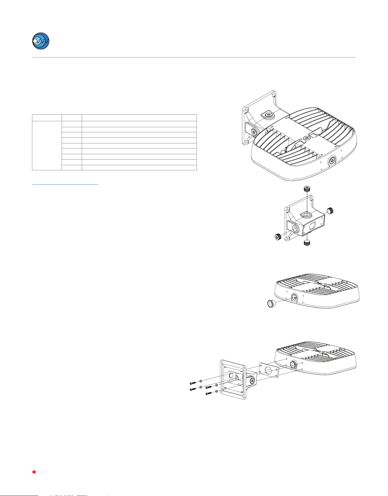
STEP 1:
Inspect shipping package and contents to ensure no
damage has occurred during shipping.
STEP 2:
Install provided 3/4 NPT conduit plugs in desired
locations. To maintain ingress rating all NPT entries
not used for wiring connections are required to be
plugged. Torque to 10 Nm (88 in-lbs)
NOTE:
To aid in assembly and protection against ingress use
of a petrolatum or soap thickened mineral oil based
thread lubricant/sealant is necessary.
STEP 3:
Install provided 3/4”NPT plastic bushing.
STEP 4:
Install Wall Mount main body with included M6 bolts
and washers and adhesive backed gasket. Apply
gasket to mount with adhisive backed side. Torque to
7 N-m (62 in-lbs)
STEP 5:
Install Back Cover Plate with 4x M4 Flat head screws
and adhesive backed gasket. Apply gasket with
adhesive side applied to mount main body.
Torque to 2 N-m (17 in-lbs)
MR-WM – WALL MOUNT INSTALLATION (Ordered Separately)
Refer to alternate instructions if using Pole, Yoke, Conduit or Hook Mount
This MR-WM kit is intended for use with UL Listed MR luminaire as
marked on the luminaire nameplate.
Accessory Package Contents
MR-WM
PART NAME
QTY
1
1
1
1
4
4
4
3
1
WALL MOUNT
WALL MOUNT PLATE
WALL MOUNT PLATE SIDE GASKET
WALL MOUNT GASKET
6 x 25mm SOCKET HEAD CAP SCREW
M4x 10mm FLAT HEAD SOCKET CAP SCREW
M6 FLAT WASHER
3/4 NPT HEX CAP PLUG
3/4 NPT THREADED SMOOTH BORE BUSHING
INSTALLATION STEPS
TM
Nemalux
I N DUSTRIAL
MR-GEN
rev. A-15
1-2
MADE IN CANADA
MR-WM – WALL MOUNT INSTALLATION (Ordered Separately)
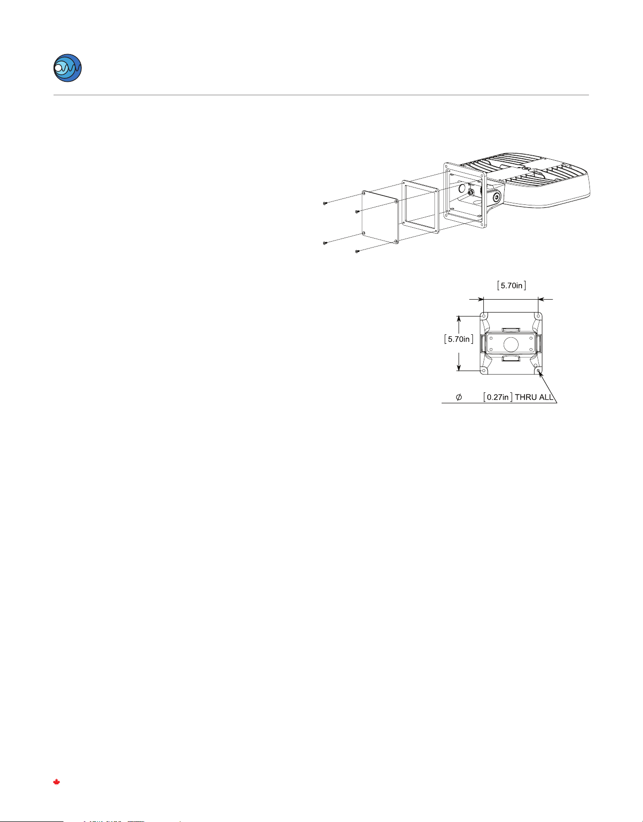
STEP 5:
Install Back Cover Plate with 4x M4 Flat head screws
and adhesive backed gasket. Apply gasket with
adhesive side applied to mount main body.
Torque to 2 N-m (17 in-lbs)
STEP 6:
Mount xture assembly to desired location using
4x 1/4-20 OR M6 Screws or Bolts.
STEP 7:
Install appropriate Listed 3/4”NPT cable gland for cable
size to desired entry location and be sure to follow all
applicable local electrical codes for the specic hazardous
locations. Torque cable gland base and dome nut to
manufacturer's recommended specication. OR Install
Direct Rigid Conduit as per local electrical code. For direct
rigid conduit installation, torque hand tight plus 2 to 3
turns.
NOTE:
To aid in assembly and protection against ingress use
of a petrolatum or soap thickened mineral oil based
thread lubricant/sealant is necessary.
STEP 8:
Resume installation instructions provided with xture.
(STEP 4)
145mm
145mm
4 x
7mm
TM
Nemalux
I N DUSTRIAL
MR-GEN
rev. A-15
2-2
MADE IN CANADA

STEP 1:
Inspect shipping package and contents to
ensure no damage has occurred during
shipping.
STEP 2:
Assemble Yoke mount with carriage bolts on
inside and with washers and nuts.
Note:
By alternating the rotation mounting hole you
can determine either an upward swing or
downward swing.
STEP 3:
Install Yoke Mount with included M6 bolts
and washers to MR Head.
Torque to 7 N-m (62 in-lbs)
STEP 4:
Mount xture assembly to desired location
2-4x 1/4-20 OR M6 Screws or Bolts.
STEP 5:
Adjust and Aim xture to desired position. Torque
hardware nuts to 9 N-m (80 in-lbs).
STEP 6:
Resume installation instructions provided
with xture. (STEP 4)
43mm
4 x
7mm
72mm
2.83in
51mm
60 deg
MR-YM – YOKE MOUNT INSTALLATION (Ordered Separately)
Refer to alternate instructions if using Pole, Wall, Conduit or Hook Mount
This MR-YM kit is intended for use with UL Listed MR luminaire as
marked on the luminaire nameplate.
Accessory Package Contents
INSTALLATION STEPS
MR-YM
PART NAME
QTY
1
1
4
4
4
YOKE MOUNT A
YOKE MOUNT B
1/4-20 HEX NUT
1/4" FLAT WASHER
1/4-20 x 0.5in CARRIAGE BOLT
90° Upward
swing
90° Downward
swing
TM
Nemalux
I N DUSTRIAL
MR-GEN
rev. A-15
1-1
MADE IN CANADA

MR-YK – HIGH VIBRATION YOKE INSTALLATION (Ordered Separately)
Refer to alternate instructions if using Conduit, Hook, Pole, Wall Mount, or Yoke Mount
STEP 1.
Inspect shipping package and contents to ensure no damage has
occurred during shipping. Discard surface/ceiling mounting bracket
provided with MR luminaire.
STEP 2.
Mount MR high vibration yoke to mounting surface using a minimum
of 4x ¼-20 or M6 fasteners (not provided).
STEP 3.
Install suitable wiring system to the conduit opening per CEC/NEC
requirements for the speci-c location of install.
NOTE:
To aid in assembly and protection against ingress use of a petrolatum or soap
thickened mineral oil based thread lubricant/sealant is necessary.
Un-used conduit opening must be plugged to maintain the integrity of the
enclosure.
STEP 4.
Mount MR Cheek Plates to sides of MR luminaire using 4x M6 at head
cap screws per side. Thread one cheek plate over installed wiring
during assembly. Torque fasteners to 5 Nm (45 in-lbs).
STEP 5.
Thread installed wiring through opening in MR high vibration yoke
mount and install MR luminaire into yoke. The raised circular bosses on
the MR cheek plates should register inside of the large circular holes on
the MR high vibration yoke mount arms. Rotate luminaire to aim in the
desired direction and fasten in place using 2x M6 socket head cap
screws and at washers per side. Torque fasteners to 5 Nm (45 in-lbs).
STEP 6.
Resume installation instructions provided with luminaire. (STEP 4 in MR
Installation Instructions provided with Luminaire)
Step 4
Step 2
This MR-YK kit is intended for use with UL Listed MR luminaire as
marked on the luminaire nameplate.
Accessory Package Contents
INSTALLATION STEPS
MR-YK
PART NAME
QTY
1
2
8
4
4
MR HIGH VIBRATION YOKE
CHEEK PLATE
M6 x 1 x 25mm SOCKET FLAT HEAD CAP SCREW
M6 FLAT WASHER
M6 x 1 x 16mm SOCKET HEAD CAP SCREW
TM
Nemalux
I N DUSTRIAL
MR-GEN
rev. A-15
1-1
MADE IN CANADA
WARNING:
The MR Head must not face upwards
by any degree beyond the vertical
position for Class II, Division 2, Zone 22,
and Class III hazardous locations.
LIGHT BEAM
HORIZON
4.3in
3.8in
108mm
95mm
2.3in
59mm
10 x
7mm
0.3in
THRU ALL
8.0in
203mm
3.1in
80mm
MR-CC –
CONDUIT CONNECTION
(Ordered Separately)
Refer to alternate instructions if using Pole, Wall, Yoke or Hook Mount
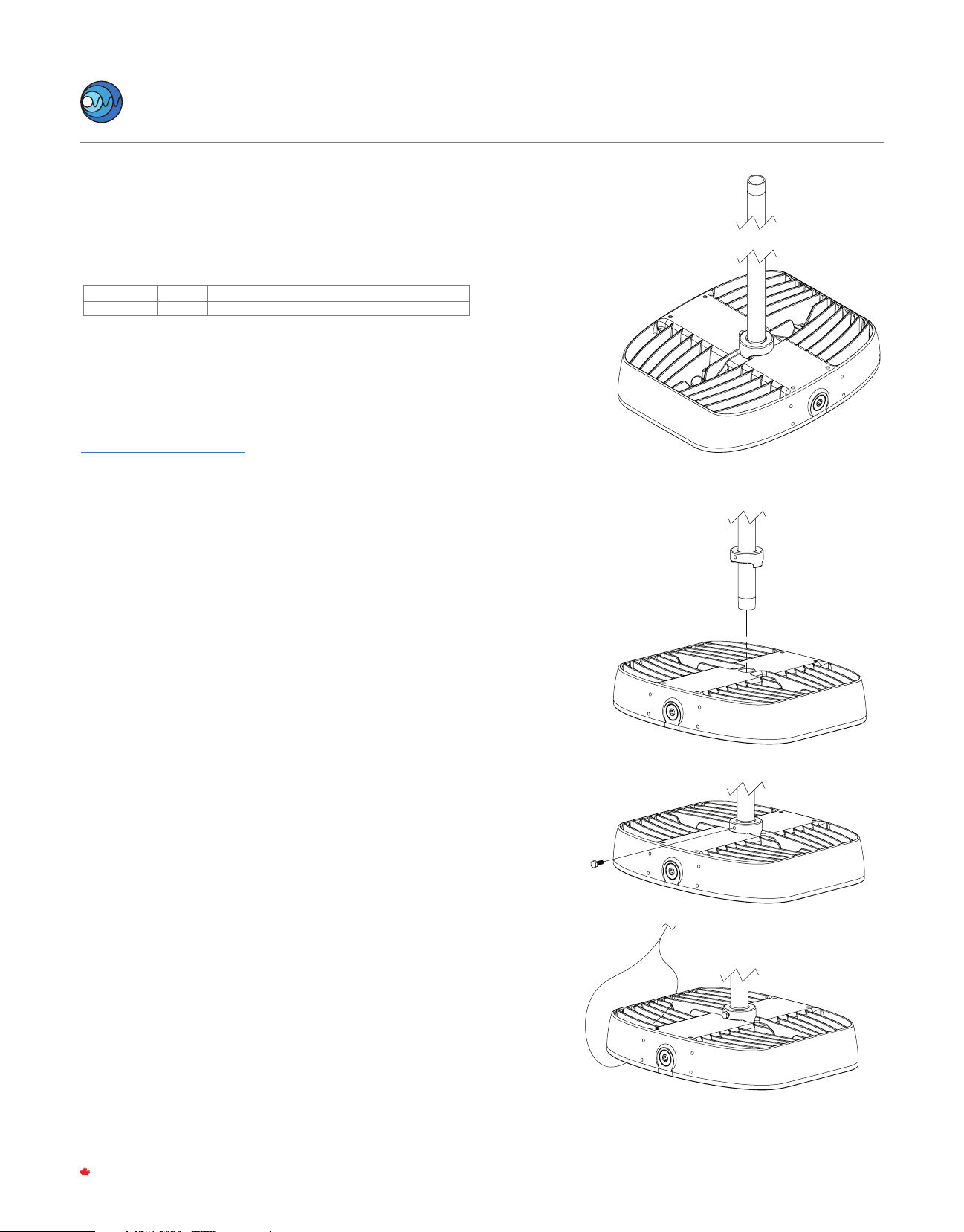
STEP 1.
Inspect shipping package and contents to ensure no damage has
occurred during shipping. Discard surface/ceiling mounting bracket
provided with MR luminaire.
STEP 2.
Slide anti-rotation lock onto suitably mounted hanging conduit and
install luminaire onto ¾”conduit. Slide anti-rotation lock into place
and tighten set screw to lock unit in place. Tighten the anti-rotation
lock set screw to 5 N-m (44 in-lbs). Fixed Rigid Metal Conduit must
be suitably mounted to prevent rotation.
NOTE:
To aid in assembly and protection against ingress use of a petrolatum or
soap thickened mineral oil based thread lubricant/sealant is necessary.
Un-used conduit opening must be plugged to maintain the integrity of the
enclosure.
STEP 3.
Install Secondary Safety Cable by looping appropriate steel cable or
chain through the outer band of the unit and fastening a closed
loop. Secondary safety hardware must be rated for a minimum of
50lbs.
Install remaining loop of secondary safety chain or steel cable to
suitable mounting location and fasten securely. Secondary safety
hardware must be rated for 50lbs.
STEP 4.
Resume installation instructions provided with Fixture. (STEP 4)
This MR-CC kit is intended for use with UL Listed MR luminaire as
marked on the luminaire nameplate.
Accessory Package Contents
INSTALLATION STEPS
MR-CC
PART NAMEQTY
1ANTI-ROTATION BRACKET ASSEMBLY
TM
Nemalux
I N DUSTRIAL
MR-GEN
rev. A-15
1-1
MADE IN CANADA
Step 2
Step 3
INSTALLATION STEPS
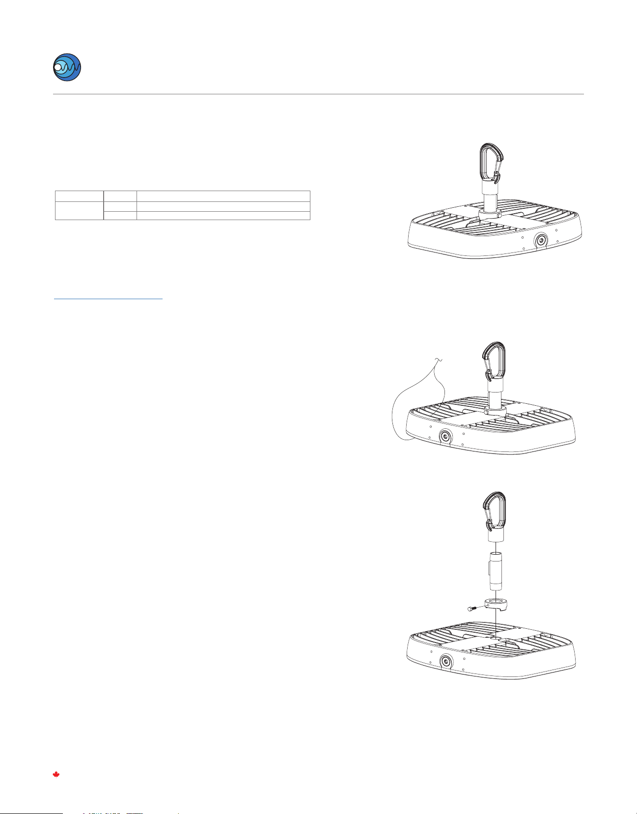
MR-HK –
HOOK PENDANT INSTALLATION
(Ordered Separately)
Refer to alternate instructions if using Pole, Wall, Yoke or Conduit Mount
TM
Nemalux
I N DUSTRIAL
MR-GEN
rev. A-15
1-1
MADE IN CANADA
Step 3
STEP 1.
Inspect shipping package and contents to ensure no damage has
occurred during shipping. Discard surface/ceiling mounting bracket
provided with MR luminaire.
STEP 2.
It is recommended to install Secondary Safety Cable by looping
appropriate steel cable or chain through the outer band of the unit and
fastening a closed loop. Secondary safety hardware must be rated for a
minimum of 50lbs. Secondary safety cables made from stainless steel
aircraft cable are available upon request.
STEP 3.
Slide anti-rotation lock onto suspension hook assembly and install hook
assembly into ¾ NPT threaded entry. Tighten to hand tight plus 1 to 2
turns. Slide anti-rotation lock into place and tighten set screw to lock
unit in place.
NOTE:
To aid in assembly and protection against ingress use of a petrolatum or soap
thickened mineral oil based thread lubricant/sealant is necessary.
Un-used conduit opening must be plugged to maintain the integrity of the
enclosure.
STEP 4.
Latch hook onto eye-bolt or other xed mounting loop. Mounting point
must be rated for a minimum of 50lbs.
STEP 5.
Install remaining loop of secondary safety chain or steel cable to
suitable mounting location and fasten securely.
STEP 6.
Resume installation instructions provided with Fixture. (STEP 4)
Step 2
This MR-HK kit is intended for use with UL Listed MR luminaire as
marked on the luminaire nameplate.
Accessory Package Contents
MR-HK
PART NAME
QTY
1
1
PENDANT HOOK ASSEMBLY
ANTI-ROTATION ASSEMBLY

STEP 1.
Remove the bottom-left pre-installed M6 x 16mm Hex Cap Screw.
STEP 2.
Install bracket on MR luminaire as shown using supplied M6 x 20mm
Hex Cap Screw. Torque M6 x 20mm Hex Cap Screw to 40 in-lbs (4.5
Nm). It is strongly recommended that a medium or high strength
thread-locker be used when installing the bracket. For units using
surface or suspension mounting, install safety kit hardware on top of
the surface mount or suspension mount brackets in the same location
as shown.
STEP 3.
Attach stainless steel chain to safety kit bracket using stainless steel
oval shaped threaded connecting link.
STEP 4.
Attach loose end of chain. Secondary safety mounting point must be
suitable for supporting a minimum of 50lbs:
- Attach loose end of stainless steel chain to xed eye-bolt (not
supplied) using the second stainless steel oval shaped thread-
ed connecting link.
- Alternate attachment method: Wrap loose end of chain
around xed beam or other immovable support and create a
closed loop using the second stainless steel oval shaped
threaded connecting link. Supporting beam or structure must
form a closed loop to prevent the secondary safety chain from
slipping o or becoming unhooked.
MR-SK-##
PART NAMEQTY
1
1
1
2
1
Secondary Safety Bracket
M6 Flat Washer
M6 x 20mm Hex Cap Screw
Oval Shaped Threaded Connecting Link
Stainless Steel Chain, 1/8”Trade Size
MR-SK-## – SECONDARY SAFETY KIT (Ordered Separately)
This MR-K-## kit is intended for use with UL Listed MR luminaire as
marked on the luminaire nameplate.
Accessory Package Contents
INSTALLATION STEPS
Step 2
Step 1
1
2
3
M6 SCREW
TM
Nemalux
I N DUSTRIAL
MR-GEN
rev. A-15
1-1
MADE IN CANADA
This manual suits for next models
2
Table of contents
Other Nemalux Lantern manuals


