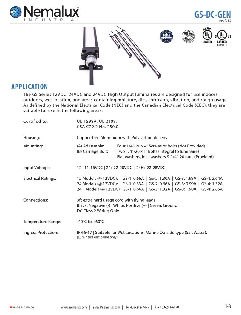
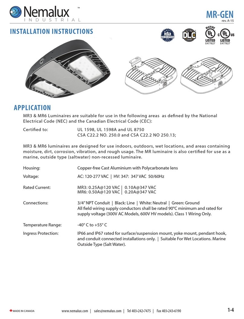
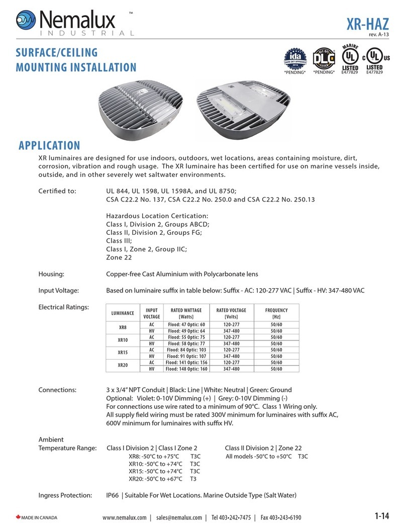
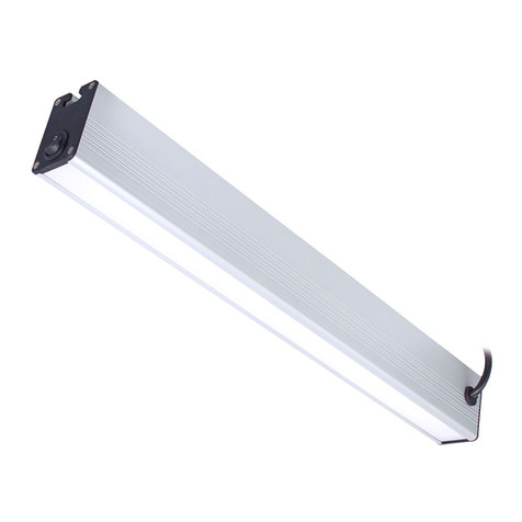
Nemalux XR8 User manual

XR luminaires are designed for use in areas subject to extended or continuous submersion
requiring IP68. The XR luminaire is also certied for use on marine vessels inside, outside and in
other severely wet saltwater environments.
XR luminaires are suitable for use in the following areas as dened by the National Electrical Code
(NEC) and the Canadian Electrical Code (CEC):
UL File Numbers: E477827
Standards that apply to all models:
UL 1598, UL 1598A and UL 8750; CSA C22.2 No. 250.0 and CSA C22.2 No. 250.13
Housing: Copper-free Cast Aluminium with Polycarbonate lens
Input Voltage: Based on luminaire sux in table below:
Sux - AC: 120-277 VAC | Sux - HV: 347-480 VAC
Electrical Ratings:
Inrush Current: XR (AC): 65A peak, 1.2ms duration
XR (HV): 65A peak, 1.2ms duration
XR-EN
rev. B-02
1-7
MADE IN CANADA
Webpage
The XR-EN Installation Manual
APPLICATION
AC
HV
AC
HV
AC
HV
AC
HV
LUMINANCE
XR8
XR10
XR15
XR20
RATED VOLTAGE
[Volts]
RATED WATTAGE
[Watts]
INPUT
VOLTAGE
120-277
347-480
120-277
347-480
120-277
347-480
120-277
347-480
60
64
75
77
103
107
156
160
FREQUENCY
[Hz]
50/60
50/60
50/60
50/60
50/60
50/60
50/60
50/60

Ambient Temperature Range:
Connections: Standard 10ft 18/3 SOOW
Dimming 10ft 18/5 SOOW
Refer to wiring diagrams for connections. Class 1 Wiring only.
All supply eld wiring must be rated 300V minimum for luminaires with sux AC,
600V minimum for luminaires with sux HV.
Ingress Protection: IP68 Continuous Submersion 25ft | Suitable for Wet Locations. | Marine Outside Type
(Salt Water)
XR-EN
rev. B-02
2-7
MADE IN CANADA
APPLICATION Cont.
LUMINANCE
XR8
XR10
XR15
XR20
Temp Range General Location
(Deg C)
-50 to 75
-50 to 74
-50 to 74
-50 to 67
WARNING
ATTENTION
Potential Electrostatic Charging Hazard
Risque potentiel de charge électrostatique
Avoid electrostatic discharge :
• Clean exterior lens surface with damp cloth only
• Éviter les décharges électrostatiques: nettoyer la surface extérieure de la lentille uniquement
avec un chion humide
To reduce the risk of electric shock,
disconnect the luminaire from the
supply circuit before opening for
installation and servicing. Keep
tightly closed when in operation.
WARNING / ATTENTION
To avoid the risk of re, explosion,
or electric shock, this product
should be installed, inspected, and
maintained by a qualied
electrician only, in accordance with
all applicable electrical codes.
Éviter tout risque d'incendie,
d'explosion ou d'électrocution, ce
produit doit être installé, inspecté
et entretenu par un électricien
qualié uniquement,
conformément à tous
codes électriques applicables.
WARNING / ATTENTION
Pour réduire le risque de choc électrique,
débranchez le luminaire du circuit
d'alimentation avant l'ouverture pour
l'installation et entretien. Gardez
hermétiquement fermé pendant le
fonctionnement.

3-7
MADE IN CANADA
XR-EN
rev. B-02
5.0in
126mm
5.2in
132mm
16.0in
405mm
17.3in
441mm
0.5in
12.7mm
0.3in
6.8mm
0.5in
12.7mm
0.5in
12.7mm
0.5in
12.7mm
0.5in
12.7mm
STEP 1.
Inspect shipping package and contents to ensure no
damage has occurred during shipping.
STEP 2.
Install Surface/Suspension Mount Brackets using the 8x M6
hex cap bracket mounting screws. See diagram for
orientation of brackets. Torque M6 bolts to 5 Nm (45 in-lbs).
STEP 3.
A) For surface mounting conguration, mount luminaire in
desired locations using 4x 1/4-20 OR 4x M6 fasteners and
washers (Not provided). One mounting hole on each
bracket is keyed to allow partial pre-installation of two
fasteners for ease of install.
B) For ceiling mounting congurations, connect 4x
anchors to the 12.7mm (0.5”) holes. Suspension hardware
(Not provided) must be rated for a minimum of 180 lbs.
STEP 4.
Terminate the supply end in a suitable listed
junction box using a suitable listed tting approved for
installation location as required.
XR-SM – SURFACE/CEILING MOUNT INSTALLATION
Refer to alternate instructions if using Hook or Yoke Mount
Step 5
Step 2
Step 3A
Step 3B
• LED Drivers will source a combined maximum of
200µA for control needs
• 0-10V Controller must sink current from LED driver
0-10V control connections
Connect the lead wires from the cord to the eld supply wiring inside the outlet box. The eld wiring
terminations are to be made following acceptable practices as outlined by the NEC / CEC
STEP 5:
Energize luminaire.
Dimming (Flying lead cable):
Black: Line | White: Neutral/Line 2 | Green: Ground
Red: Dimming (+) | Orange: Dimming
Black: Line 1 (L1) | White: Neutral/Line 2 | Green: Ground
All eld wiring supply conductors shall be rated 90°C
minimum and rated for supply voltage (300V AC Models,
600V HV models).

4-7
MADE IN CANADA
XR-EN
rev. B-02
XR-YK – HIGH VIBRATION YOKE
INSTALLATION
Refer to alternate instructions if using Hook or Yoke Mount
STEP 1.
Inspect shipping package and contents to ensure no damage has
occurred during shipping.
STEP 2.
Mount XR high vibration yoke to mounting surface using a
minimum of 4x ¼-20 or M6 fasteners (not provided).
STEP 3.
Mount XR Cheek Plates to sides of XR luminaire using 4x M6 at
head cap screws per side. Thread one cheek plate over installed
wiring during assembly. Torque fasteners to 5 Nm (45 in-lbs).
STEP 4.
Thread installed wiring through opening in XR high vibration
yoke mount and install XR luminaire into yoke. The raised circular
bosses on the XR cheek plates should register inside of the large
circular holes on the XR high vibration yoke mount arms. Rotate
luminaire to aim in the desired direction and fasten in place using
2x M6 socket head cap screws and at washers per side. Torque
fasteners to 5 Nm (45 in-lbs).
STEP 5.
Resume installation instructions provided with luminaire
(STEP 4 on PAGE 3).
Step 4
Step 2
This XR-YK kit is intended for use with UL Listed XR
luminaire as marked on the luminaire nameplate.
Accessory Package Contents
XR-YK
PART NAMEQTY
1
2
8
4
4
XR HIGH VIBRATION YOKE
CHEEK PLATE
M6 x 1 x 25mm SOCKET FLAT HEAD CAP SCREW
M6 FLAT WASHER
M6 x 1 x 16mm SOCKET HEAD CAP SCREW
8.0in
4.3in
203mm
108mm
3.8in
95mm
2.3in
59mm
10 x
7mm
0.3in
THRU ALL
3.1in
80mm

5-7
MADE IN CANADA
XR-EN
rev. B-02
4.3in
108.15mm
2.3in
59mm
0.27in
6.76mm
0.27in
6.8mm
1.7in
44mm
2.8in
70mm
XR-YM – YOKE MOUNT INSTALLATION
Refer to alternate instructions if using Hook or High Vibration Yoke Mount
STEP 1.
Inspect shipping package and contents to ensure no damage
has occurred during shipping.
STEP 2.
Loosely assemble Yoke mount with carriage bolts on inside and
washers and nuts on the outside.
NOTE: Depending on which mounting hole is used in the curved
slot, the luminaire may be congured for an upward or downward
adjustable swing.
STEP 3.
Thread installed wiring through openings in yoke mount cheek
plate and yoke mount bracket. Mount yoke assembly to
luminaire using 4x M6 Socket Head Cap Screws and Washers
(Provided). Torque fasteners to 5 Nm (45 in-lbs).
STEP 4.
Mount luminaire assembly to desired location using 4x 1/4-20
OR M6 Screws or Bolts (Not Provided).
STEP 5.
Adjust and aim luminaire to desired position. Torque hardware
nuts to 9 N-m (80 in-lbs).
STEP 6.
Resume installation instructions provided with luminaire
(STEP 4 on PAGE 3). Step 5
Step 3
This XR-YM kit is intended for use with UL Listed XR
luminaire as marked on the luminaire nameplate.
Accessory Package Contents
XR-YM
PART NAMEQTY
1
1
1
4
4
4
4
YOKE MOUNT A
YOKE MOUNT B
CHEEK PLATE
1/4-20 HEX NUT
1/4" FLAT WASHER
1/4-20 x 0.5in CARRIAGE BOLT
M6 x 25mm HEX HEAD CAP SCREW

6-7
MADE IN CANADA
XR-EN
rev. B-02
XR-HK – HOOK PENDANT INSTALLATION
Refer to alternate instructions if using Yoke Mount
STEP 1.
Inspect shipping package and contents to ensure no damage
has occurred during shipping.
STEP 2.
It is recommended to install Secondary Safety Cable by
looping appropriate steel cable or chain through the outer
band of the unit and fastening a closed loop. Secondary safety
hardware must be rated for a minimum of 110lbs. Secondary
safety cables made from stainless steel aircraft cable are
available upon request.
STEP 3.
Latch hook onto eye-bolt or other xed mounting loop.
Mounting point must be rated for a minimum of 110lbs.
STEP 4.
Install remaining loop of secondary safety chain or steel cable
to suitable mounting location and fasten securely.
STEP 5.
Resume installation instructions provided with luminaire
(STEP 4 on PAGE 3).
Step 2

7-7
MADE IN CANADA
XR-EN
rev. B-02
Step 2
Step 1
STEP 1.
Remove the bottom-left pre-installed M6 x 16mm Hex Cap Screw.
STEP 2.
Install bracket on XR luminaire as shown using supplied M6 x 20mm Hex
Cap Screw. Torque M6 x 20mm Hex Cap Screw to 40 in-lbs (4.5 Nm). It is
strongly recommended that a medium or high strength thread-locker be
used when installing the bracket. For units using surface or suspension
mounting, install safety kit hardware on top of the surface mount or
suspension mount brackets in the same location as shown.
STEP 3.
Attach stainless steel chain to safety kit bracket using stainless steel oval
shaped threaded connecting link.
STEP 4.
Attach loose end of chain. Secondary safety mounting point must be
suitable for supporting a minimum of 120lbs:
- Attach loose end of stainless steel chain to xed eye-bolt (not
supplied) using the second stainless steel oval shaped threaded
connecting link.
- Alternate attachment method: Wrap loose end of chain around
xed beam or other immovable support and create a closed loop
using the second stainless steel oval shaped threaded connecting
link. Supporting beam or structure must form a closed loop to
prevent the secondary safety chain from slipping o or becoming
unhooked.
XR-SK-##
PART NAMEQTY
1
1
1
2
1
1003-01-02-301 (ZLM Secondary Safety)
M6 Flat Washer
M6 x 20mm Hex Cap Screw
Oval Shaped Threaded Connecting Link
Stainless Steel Chain, 1/8”Trade Size
XR-SK-## – SECONDARY SAFETY KIT (Ordered Separately)
This XR-SK-## kit is intended for use with UL Listed XR
luminaire as marked on the luminaire nameplate.
Accessory Package Contents
1
2
3
M6 SCREW
This manual suits for next models
3
Table of contents
Other Nemalux Lantern manuals
Popular Lantern manuals by other brands

LIVARNO LUX
LIVARNO LUX 295794 Assembly, operating and safety instructions
HAMPTON BAY
HAMPTON BAY HB7024-05TP Use and care guide

RealFlame
RealFlame Outdoor Living 160 Redvale manual

LIVARNO LUX
LIVARNO LUX Z31906 Assembly, operating and safety instructions

ETC
ETC ArcSystem Navis 100 installation guide
Above All
Above All VISION LED STRIP instruction manual
