manuals.online logo
Brands
  1. Home
  2. •
  3. Brands
  4. •
  5. Madas
  6. •
  7. Control Unit
  8. •
  9. Madas EVAP-1-3-6/NA User manual

Madas EVAP-1-3-6/NA User manual

ELETTROVALVOLE AUTOMATICHE DI SFIATO TIPO EVA.../NA - EVAP.../NA
EVA.../NA - EVAP.../NA AUTOMATIC RELIEF SOLENOID VALVES
ELECTROVANNES AUTOMATIQUES D’EFFLEUREMENT DE TYPE EVA.../NA - EVAP.../NA
ELECTROVÁLVULAS DE ALIVIO AUTOMÁTICAS TIPO EVA.../NA - EVAP.../NA
Capitolo - Chapter
Chapìtre - Capitulo
4
1
EVA/NA
EVAP/NA
Madas Technical Manual
March 2012
DESCRIZIONE
Elettrovalvola automatica di sato aperta in assenza di corrente, chiude se alimentata
elettricamente.
Conforme Direttiva 97/23/CE (Direttiva PED)
Conforme Direttiva 94/9/CE (Direttiva ATEX)
Conforme Direttiva 2004/108/CE (Compatibilità Elettromagnetica)
Conforme Direttiva 2006/95/CE (Bassa Tensione)
CARATTERISTICHE TECNICHE
• Impiego: gas non aggressivi delle 3 famiglie (gas secchi)
• Attacchi lettati Rp: (DN 15 - DN 50) secondo EN 10226
• Tensione di alimentazione: (DN 15 - DN 20 - DN 25)
12 Vdc, 12 V/50 Hz, 24 Vdc, 24 V/50 Hz, 110 V/50 Hz, 230 V/50-60 Hz
• Tensione di alimentazione: (DN 32 - DN 40 - DN 50)
24 Vdc, 24 V/50 Hz, 110 V/50 Hz, 230 V/50-60 Hz
• Tolleranza su tensione di alimentazione: -15% ... +10%
• Pressione max esercizio: 0,36 - 1 - 3 - 6 bar (vedi etichetta prodotto)
• Temperatura ambiente: -20 ÷ +60 °C
• Temperatura superciale max: 80 °C
• Grado di protezione: IP65
DESCRIPTION
Automatic relief valve solenoid valve open without tension, closed if it is electrically
powered.
In conformity with the 97/23/EC Directive (Ped Directive)
In conformity with the 94/9/EC Directive (Atex Directive)
In conformity with the 2004/108/EC Directive (Electromagnetic Compatibility)
In conformity with the 2006/95/EC Directive (Low Voltage)
TECHNICAL DATA
• Use: not aggressive gases of the 3 families (dry gases)
• Threaded connections Rp: (DN 15 - DN 50) according to EN 10226
• Power supply voltage: (DN 15 - DN 20 - DN 25)
12 Vdc, 12 V/50 Hz, 24 Vdc, 24 V/50 Hz, 110 V/50 Hz, 230 V/50-60 Hz
• Power supply voltage: (DN 32 - DN 40 - DN 50)
12 Vdc, 12 V/50 Hz, 24 Vdc, 24 V/50 Hz, 110 V/50 Hz, 230 V/50-60 Hz
• Power supply voltage tolerance: -15% ... +10%
• Max. working pressure: 0,36 - 1 - 3 - 6 bar (see product label)
• Environment temperature: -20 ÷ +60 °C
• Max supercial temperature: 80 °C
• Protection degree: IP65
EVAP-1-3-6/NA
EVA-1-3-6/NA
0497
II 3G - II 3D
MADAS-01
ELETTROVALVOLE AUTOMATICHE DI SFIATO TIPO EVA.../NA - EVAP.../NA
EVA.../NA - EVAP.../NA AUTOMATIC RELIEF SOLENOID VALVES
ELECTROVANNES AUTOMATIQUES D’EFFLEUREMENT DE TYPE EVA.../NA - EVAP.../NA
ELECTROVÁLVULAS DE ALIVIO AUTOMÁTICAS TIPO EVA.../NA - EVAP.../NA
Capitolo - Chapter
Chapìtre - Capitulo
4
2Madas Technical Manual
March 2012
EVA/NA
EVAP/NA
INSTALLAZIONE
ATTENZIONE: le operazioni di installazione/cablaggio/taratura devono essere
eseguite da personale qualicato.
L’ elettrovalvola è conforme alla Direttiva 94/9/CE (denominata Direttiva ATEX 100 a)
come apparecchio del gruppo II, categoria 3G e come apparecchio II, categoria 3D; come
tale è idonea per essere installata nelle zone 2 e 22 come classicate nell’allegato I alla
Direttiva 99/92/CE.
L’elettrovalvola non è idonea per l’utilizzo nelle zone 1 e 21 e, a maggior ragione, nelle
zone 0 e 20 come denite nella già citata Direttiva 99/92/CE.
Per determinare la qualica e l’estensione delle zone pericolose si veda la norma EN
60079-10.
L’apparecchio, se installato e sottoposto a manutenzione nel pieno rispetto di tutte le
condizioni e istruzioni tecniche riportate nel presente documento, non costituisce fonte di
pericoli specici: in particolare, in condizioni di normale funzionamento, non è prevista, da
parte dell’elettrovalvola, l’emissione in atmosfera di sostanza inammabile con modalità
tali da originare un’atmosfera esplosiva.
ATTENZIONE: le operazioni di installazione/cablaggio/manutenzione devono
essere eseguite da personale qualicato.
• E’ necessario chiudere il gas prima dell’installazione.
• Vericare che la pressione di linea NON SIA SUPERIORE alla pressione massima
dichiarata sull’etichetta del prodotto.
• L’elettrovalvola deve essere installata con la freccia (indicata sul corpo rivolta verso l’utenza.
• E’ necessario installare l’elettrovalvola in posizione orizzontale (come nell’esempio di
installazione).
Non può essere installata in posizione verticale o capovolta.
• Durante l’installazione evitare che detriti o residui metallici penetrino all’interno
dell’apparecchio.
• Vericare che la lunghezza del letto della tubazione non sia eccessiva per non
danneggiare il corpo dell’apparecchio in fase di avvitamento. Non usare la bobina come
leva per l’avvitamento ma servirsi dell’apposito utensile.
• In ogni caso dopo l’installazione vericare la tenuta dell’impianto.
COLLEGAMENTI ELETTRICI
• Prima di effettuare connessioni elettriche vericare che la tensione di rete corrisponda
con la tensione di alimentazione indicata sull’etichetta del prodotto.
• Scollegare l’alimentazione prima di procedere al cablaggio.
• Cablare il connettore con cavo tipo H05RN-F 3X0,75mm², Ø esterno da 6,2 a 8,1mm
avendo cura di assicurare il grado IP65 del prodotto.
• Nel cablare il connettore usare gli appositi terminali per cavi.
• Collegare all’alimentazione i morsetti 1 e 2 e il cavo di terra al morsetto .
• IMPORTANTE: con alimentazioni 12Vdc e 24 Vdc con energy saving rispettare la
polarità.
La bobina è idonea anche per alimentazione permanente. Il riscaldamento della bobina
in caso di servizio continuo è un fenomeno del tutto normale. E’ consigliabile evitare il
contatto a mani nude con la bobina dopo un alimentazione elettrica continua superiore
a 20 minuti. In caso di manutenzione aspettare il raffreddamento della bobina o
eventualmente usare idonee protezioni.
L’elettrovalvola può essere fornita anche con il microswitch di segnalazione.
In questo caso, con alimentazioni 12 Vdc e 24 Vdc, rispettare la polarità di alimentazione
della bobina.
INSTALLATION
WARNING: all installation/wiring/setting work must be carried out by skilled
staff.
The solenoid valve is in conformity with the Directive 94/9/CE (said Directive ATEX 100
a) as device of group II, category 3G and as device of group II, category 3D; for this
reason it is suitable to be installed in the zones 2 and 22 as classied in the attachment
I to the Directive 99/92/EC.
The solenoid valve is not suitable to be used in zones 1 and 21 and, all the more so, in
zones 0 and 20 as classied in the already said Directive 99/92/EC.
To determine the qualication and the extension of the dangerous zones, see the norm
EN 60079-10.
The device, if installed and serviced respecting all the conditions and the technical
instructions of this document, is not source of specic dangers: in particular, during the
normal working, is not forecast, by the solenoid valve, the emission in the atmosphere of
inammable substance in way to cause an explosive atmosphere.
WARNING: all installation/wiring/maintenance work must be carried out by
skilled staff.
• The gas supply must be shut off before installation.
• Check that the line pressure DOES NOT EXCEED the maximum pressure stated on
the product label.
• The solenoid valve must be installed with the arrow (on the body) towards the user
on gas pipe.
• It is necessary to install the solenoid valve in horizontal position (as in the installation
example). It cannot be installed in vertical position or overturned.
• During installation take care not to allow debris or scraps of metal to enter the device.
• Check that the pipeline thread is not too long; overlong threads may damage the body
of the device when screwed into place. Do not use the coil for leverage when screwing
into position; use the appropriate tool.
• Always check that the system is gas-tight after installation.
ELECTRICAL CONNECTIONS
• Before making electrical connections, check that the mains voltage is the same as the
power supply voltage stated on the product label.
• Disconnect the power supply before wiring.
• Wire the connector with H05RN-F 3X0.75mm² cable outside Ø from 6.2 a 8.1mm,
taking care to ensure that the device has IP65 protection.
• Use cable terminals when wiring the connector.
• Connect the power supply to terminals 1 and 2 and the ground wire to terminal .
• IMPORTANT: with tension 12Vdc and 24Vdc with energy saving observe the polarity.
The coil is also suitable for permanent power supply. In case of continuous duty, it is
absolutely normal for the coil to heat up. The coil should not be touched with bare hands
after it has been continuously powered for more than 20 minutes. Before maintenance
work, wait for the coil to cool or use suitable protective equipment.
The solenoid valve can be supplied also with the signalation microswitch.
In this case, with 12 Vdc and 24 Vdc power, you have to respect the polarity of the coil.
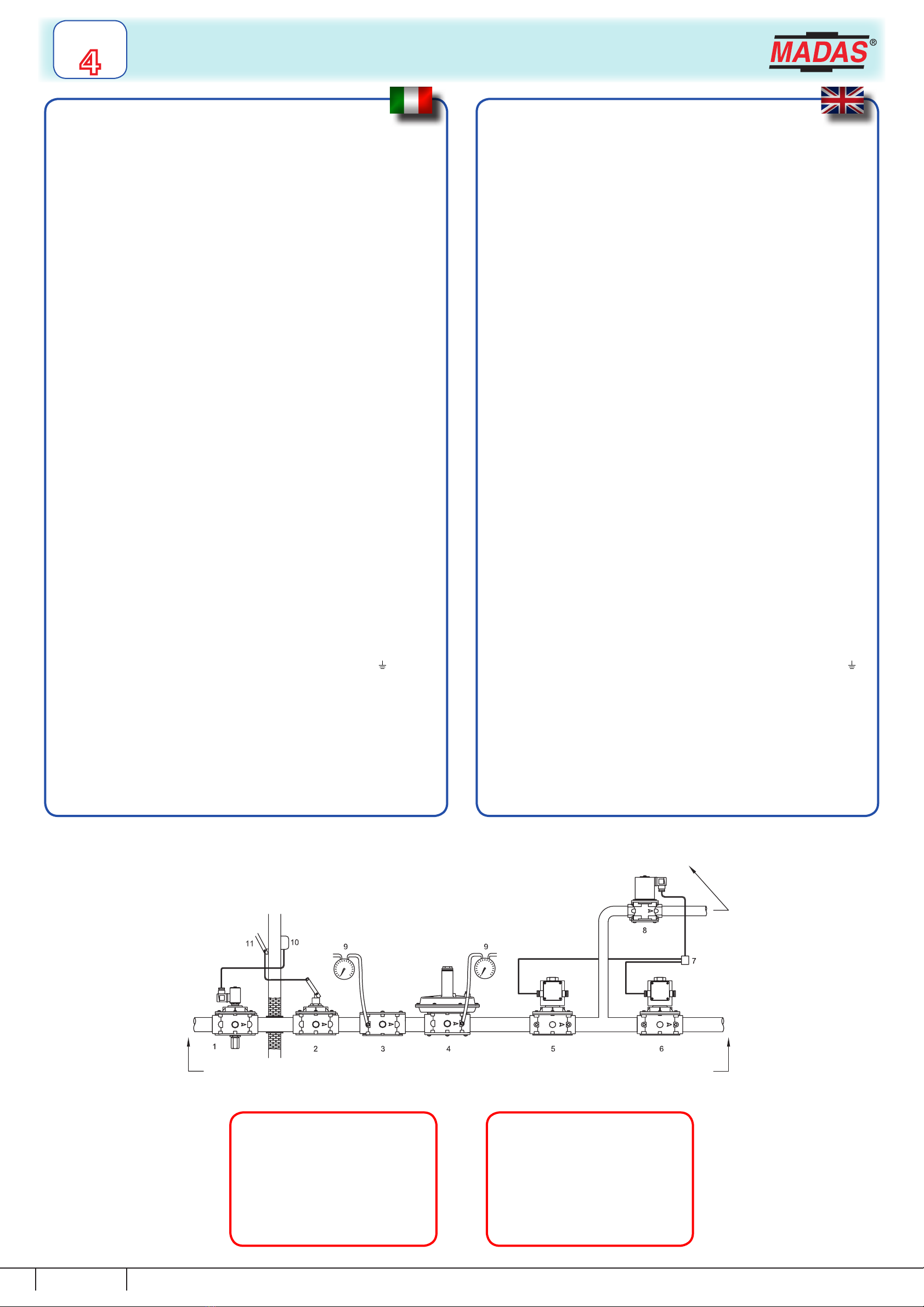
ESEMPIO DI INSTALLAZIONE
1. Elettrovalvola a riarmo manuale M16/RM N.C.
2. Valvola a strappo SM
3. Filtro gas FM
4. Regolatore di pressione RG/2MC
5. Elettrovalvola automatica tipo EVP/NC o EVPF/NC
6. Elettrovalvola automatica tipo EVP/NC o EVPF/NC
7. Dispositivo di comando elettrovalvole
8. Elettrovalvola di sato tipo EVA/NA
9. Manometro
10. Rivelatore gas
11. Leva comando a distanza valvola a strappo SM
rete - pipe
EXAMPLE OF INSTALLATION
1. M16/RM N.C. manual reset solenoid valve
2. SM series jerk handle ON/OFF valve
3. Gas lter type FM
4. Gas pressure regulator type RG/2MC
5. Automatic solenoid valve type EVP/NC or EVPF/NC
6. Automatic solenoid valve type EVP/NC or EVPF/NC
7. Solenoid valves control device
8. Relief solenoid valve type EVA/NA
9. Manometer
10. Gas detector
11. Lever for remote SM ON/OFF valve control
testa di combustione
combustion head
Scarico in aria libera
Free air exhaust
ELETTROVALVOLE AUTOMATICHE DI SFIATO TIPO EVA.../NA - EVAP.../NA
EVA.../NA - EVAP.../NA AUTOMATIC RELIEF SOLENOID VALVES
ELECTROVANNES AUTOMATIQUES D’EFFLEUREMENT DE TYPE EVA.../NA - EVAP.../NA
ELECTROVÁLVULAS DE ALIVIO AUTOMÁTICAS TIPO EVA.../NA - EVAP.../NA
Capitolo - Chapter
Chapìtre - Capitulo
4
3
EVA/NA
EVAP/NA
Madas Technical Manual
March 2012
Dimensioni di ingombro in mm - Overall dimensions in mm
Mesures d’encombrement en mm - Dimensiones en mm
Attacchi lettati
Threaded connections
Fixations letees
Conexiones roscadas
Attacchi angiati
Flanged connections
Fixations bridees
Conexiones de brida
P. max
(bar) A B C
DN 15 - DN 20 - DN 25 - 0,36 70 130 74
DN 15 - DN 20 - DN 25 - 1 - 3 - 6 70 152 74
DN 32- DN 40 - DN 50 - 1 - 3 - 6 160 250 140
DN 25 0,36 142 147 115
DN 25 1 - 3 - 6 142 187 115
DN 32- DN 40 - DN 50 1 - 3 - 6 230 260 140
Bobine e connettori per elettrovalvole EVAP/NA (P. max 360 mbar)
Coils and connectors for EVAP/NA solenoid valve (P. max 360 mbar)
Attacchi
Connections
Voltaggio
Voltage
Codice bobina
Coil code
Timbratura bobina
Coil stamping
Codice connettore
Connector code
Tipo connettore
Connector type
EVAP/NA
DN 15 - DN 20 - DN 25
12 Vdc BO-0400 BO-0400
12 VDC 17W CN-0010 NORMALE
NORMAL
12 V/50 Hz BO-0400 BO-0400
12 VDC 17W CN-0050
RADDRIZZATORE
RECTIFIER
24 Vdc BO-0410 BO-0410
24 VDC 17W CN-0010 NORMALE
NORMAL
24 V/50 Hz BO-0410 BO-0410
24 VDC 17W CN-0050
RADDRIZZATORE
RECTIFIER
110 V/50-60 Hz BO-0420 BO-0420
110 V RAC 17W CN-0045
RADDRIZZATORE
RECTIFIER
230 V/50-60 Hz BO-0430 BO-0430
230 V RAC 17W CN-0045
RADDRIZZATORE
RECTIFIER
ELETTROVALVOLE AUTOMATICHE DI SFIATO TIPO EVA.../NA - EVAP.../NA
EVA.../NA - EVAP.../NA AUTOMATIC RELIEF SOLENOID VALVES
ELECTROVANNES AUTOMATIQUES D’EFFLEUREMENT DE TYPE EVA.../NA - EVAP.../NA
ELECTROVÁLVULAS DE ALIVIO AUTOMÁTICAS TIPO EVA.../NA - EVAP.../NA
Capitolo - Chapter
Chapìtre - Capitulo
4
4
EVA/NA
EVAP/NA
Madas Technical Manual
March 2012
Bobine e connettori per elettrovalvole EVAP-1-3-6/NA (P. max 1 - 3 - 6 bar)
Coils and connectors for EVAP-1-3-6/NA solenoid valve (P. max 1 - 3 - 6 bar)
Attacchi
Connections
Voltaggio
Voltage
Codice bobina
Coil code
Timbratura bobina
Coil stamping
Codice connettore
Connector code
Tipo connettore
Connector type
EVAP-1/NA
DN 15 - DN 20 - DN 25
12 Vdc BO-0400 BO-0400
12 VDC 17W CN-0010 NORMALE
NORMAL
12 V/50 Hz BO-0400 BO-0400
12 VDC 17W CN-0050
RADDRIZZATORE -
RECTIFIER
24 Vdc BO-0410 BO-0410
24 VDC 17W CN-0010 NORMALE
NORMAL
24 V/50 Hz BO-0410 BO-0410
24 VDC 17W CN-0050
RADDRIZZATORE
RECTIFIER
110 V/50-60 Hz BO-0420 BO-0420
110 V RAC 17W CN-0045
RADDRIZZATORE
RECTIFIER
230 V/50-60 Hz BO-0430 BO-0430
230 V RAC 17W CN-0045
RADDRIZZATORE
RECTIFIER
EVAP- 3 - 6 /NA
DN 15 - DN 20 - DN 25
12 Vdc BO-0510 BO-0510
12 VDC 28W CN-2100 NORMALE + Energy Saving
NORMAL + Energy Saving
12 V/50 Hz BO-0510 BO-0510
12 VDC 28W CN-2110
RADDRIZZATORE
+ Energy Saving
RECTIFIER + Energy Saving
24 Vdc BO-0520 BO-0520
24 VDC 28W CN-2100 NORMALE + Energy Saving
NORMAL + Energy Saving
24 V/50 Hz BO-0520 BO-0520
24 VDC 28W CN-2110
RADDRIZZATORE
+ Energy Saving
RECTIFIER + Energy Saving
110 V/50 Hz BO-0530 BO-0530
110 V RAC 28W CN-2130
RADDRIZZATORE
+ Energy Saving
RECTIFIER
+ Energy Saving
230 V/50-60 Hz BO-0540 BO-0540
230 V RAC 28W CN-2130
RADDRIZZATORE
+ Energy Saving
RECTIFIER + Energy Saving
Bobine e connettori per elettrovalvole EVA-1-3-6 /NA
Coils and connectors for EVA-1-3-6 /NA solenoid valve
Attacchi
Connections
Voltaggio
Voltage
Codice bobina
Coil code
Timbratura bobina
Coil stamping
Codice connettore
Connector code
Tipo connettore
Connector type
EVA-1/NA - EVA-3/NA
(P.max 1 - 3 bar)
DN 32 - DN 40 - DN 50
24 Vdc BO-0300 BO-0300
24 VDC W45 CN-2100 NORMALE + Energy Saving
NORMAL + Energy Saving
24 V/50 Hz BO-0300 BO-0300
24 VDC W45 CN-2110
RADDRIZZATORE
+ Energy Saving
RECTIFIER + Energy Saving
110 V/50 Hz BO-0310 BO-0310
V 98 DC W45 CN-2130
RADDRIZZATORE
+ Energy Saving
RECTIFIER
+ Energy Saving
230 V/50-60 Hz BO-0320 BO-0320
V 196 DC W45 CN-2130
RADDRIZZATORE
+ Energy Saving
RECTIFIER + Energy Saving
EVA-6/NA
(P.max 6 bar)
DN 32 - DN 40 - DN 50
24 Vdc BO-0355 BO-0355
24V RAC ES CN-2100 NORMALE + Energy Saving
NORMAL + Energy Saving
24 V/50 Hz BO-0355 BO-0355
24V RAC ES CN-2110
RADDRIZZATORE
+ Energy Saving
RECTIFIER + Energy Saving
110 V/50 Hz BO-0365 BO-0365
110 V RAC ES CN-2130
RADDRIZZATORE
+ Energy Saving
RECTIFIER
+ Energy Saving
230 V/50-60 Hz BO-0375 BO-0375
230 V RAC ES CN-2130
RADDRIZZATORE
+ Energy Saving
RECTIFIER + Energy Saving

This manual suits for next models

1

Other Madas Control Unit manuals

Madas M16/RMO NA/NC User manual

Madas

Madas M16/RMO NA/NC User manual

Madas EVO/NC User manual

Madas

Madas EVO/NC User manual

Madas M16/RMOJ N.A. User manual

Madas

Madas M16/RMOJ N.A. User manual

Madas M16/RMO NA/NC User manual

Madas

Madas M16/RMO NA/NC User manual

Madas XVR-1-3-6 User manual

Madas

Madas XVR-1-3-6 User manual

Madas EVPF/NC User manual

Madas

Madas EVPF/NC User manual

Madas MVB/1 MAX User manual

Madas

Madas MVB/1 MAX User manual

Madas M16/RMJ N.A. User manual

Madas

Madas M16/RMJ N.A. User manual

Madas EV-1 User manual

Madas

Madas EV-1 User manual

Madas JW-1 Series User manual

Madas

Madas JW-1 Series User manual

Madas MVB/1 MIN User manual

Madas

Madas MVB/1 MIN User manual

Madas MVB/1 MAX User manual

Madas

Madas MVB/1 MAX User manual

Madas CE-51CN4180 User manual

Madas

Madas CE-51CN4180 User manual

Madas M16/RMOX N.A. User manual

Madas

Madas M16/RMOX N.A. User manual

Madas EV-1 User manual

Madas

Madas EV-1 User manual

Madas EVQ-1 EEX User manual

Madas

Madas EVQ-1 EEX User manual

Madas M16/RMO N.A. User manual

Madas

Madas M16/RMO N.A. User manual

Madas XVP/NC Series User manual

Madas

Madas XVP/NC Series User manual

Madas M16/RM N.C. DN 65 EEX User manual

Madas

Madas M16/RM N.C. DN 65 EEX User manual

Madas M16/RM N.C. DN 65 EEX User manual

Madas

Madas M16/RM N.C. DN 65 EEX User manual

Madas M16/RMC N.A. User manual

Madas

Madas M16/RMC N.A. User manual

Madas M14/RM N.C User manual

Madas

Madas M14/RM N.C User manual

Madas EV-1 User manual

Madas

Madas EV-1 User manual

Madas M16/RM N.A. User manual

Madas

Madas M16/RM N.A. User manual

Popular Control Unit manuals by other brands

GE IC3645SR3R404R2 Installation and operation manual

GE

GE IC3645SR3R404R2 Installation and operation manual

GEM eSyStep Q50 operating instructions

GEM

GEM eSyStep Q50 operating instructions

CEVA FSP201 quick start guide

CEVA

CEVA FSP201 quick start guide

Paser UNICOM CF0012UNAL21 installation manual

Paser

Paser UNICOM CF0012UNAL21 installation manual

National Instruments 2591 installation guide

National Instruments

National Instruments 2591 installation guide

Nice Moon MC424 Instructions and warnings for installation and use

Nice

Nice Moon MC424 Instructions and warnings for installation and use

Monster MTS DESK instruction manual

Monster

Monster MTS DESK instruction manual

IBM 2702 Information guide

IBM

IBM 2702 Information guide

Zamel ROW-01 quick start guide

Zamel

Zamel ROW-01 quick start guide

Seco Q7-928 user manual

Seco

Seco Q7-928 user manual

Enerpac VM2 instruction sheet

Enerpac

Enerpac VM2 instruction sheet

Vega VEGAKON 66 operating instructions

Vega

Vega VEGAKON 66 operating instructions

Lenze E84AYCEC Communications manual

Lenze

Lenze E84AYCEC Communications manual

CBE SP5 Series instructions

CBE

CBE SP5 Series instructions

Aewin Technologies CB-7960 user manual

Aewin Technologies

Aewin Technologies CB-7960 user manual

netvox RB02I user manual

netvox

netvox RB02I user manual

FNW FIGURE 751 Installation, operation & maintenance instructions

FNW

FNW FIGURE 751 Installation, operation & maintenance instructions

EG&G ORTEC 426 Operating and service manual

EG&G

EG&G ORTEC 426 Operating and service manual

manuals.online logo
manuals.online logoBrands
  • About & Mission
  • Contact us
  • Privacy Policy
  • Terms and Conditions

Copyright 2025 Manuals.Online. All Rights Reserved.