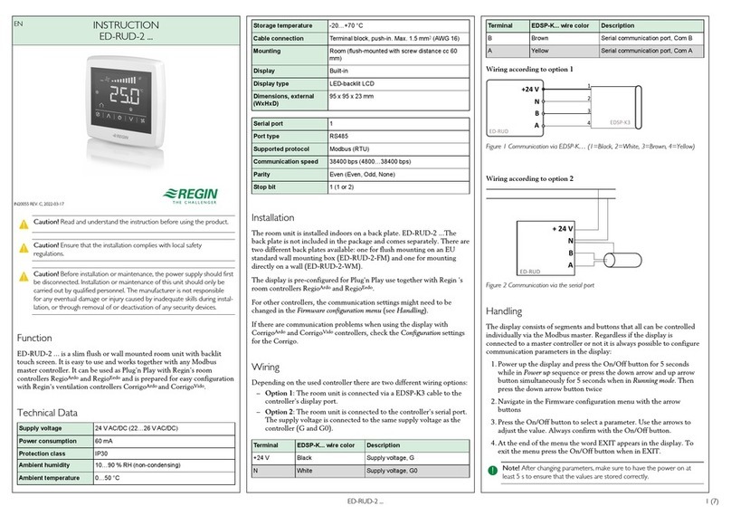
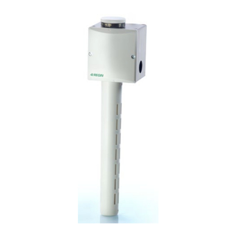
Regin TRT50 User manual

EN INSTRUCTION
TRT50(-420)
IN20078 REV. A, 2022-10-12
CCaauuttiioonn!! Rea an un erstan the instruction before using the pro uct.
CCaauuttiioonn!! Ensure that the installation complies with local safety
regulations.
CCaauuttiioonn!! Before installation or maintenance, the power supply shoul first
be isconnecte . Installation or maintenance of this unit shoul only be
carrie out by qualifie personnel. The manufacturer is not responsible
for any eventual amage or injury cause by ina equate skills uring instal-
lation, or through removal of or eactivation of any security evices.
Function
TRT50 is a wall mounted temperature sensor for measuring temperature
in air handling systems. Available with 0...10V DC (TRT50 or
4...20mA (TRT50-420 output.
Technical Data
Supply voltage 24 V AC ± 20 % or 15...35 V DC (0...10 V output signal),
alt. 20...35 V DC (4...20 mA)
Output signal
TRT50
TRT50-420
0...10 V DC proportional to measuring range 0...+50°C
4...20 mA
Load impedance
TRT50
TRT50-420
Min. 10 kΩ
Max. 500 Ω
Ambient
temperature
-5...+50°C
Storage
temperature
-20…+70°C
Measurement
accuracy
± 0.5°C at 20°C
Cable connection Terminal blocks, max. 1.5 mm
Sensor type KF6645 class DIN B, IEC 751
Protection class IP65
Weight 0.25 kg
Dimensions
80
80
35
50
32
Ø12
PG7
[mm]
Installation
Mount the sensor on a wall. It should be located where the air can
circulate freely. Avoid locations where it can be exposed to disturbances
that may influence the readings, i.e. near doors, radiators, on sunlit walls
etc. When mounted in contaminated environments the sensor’s
membrane filter should be exchanged for a sintered brass filter.
Wiring
Connect supply voltage and output signals according to the
diagram for the unit being installed.
20...35 V DC
15...35 V DC
24 V AC ± 20 %
G G0 T G T
0...10 V 4...20 mA
This product carries the CE-mark. More information is available at
www.regincontrols.com.
Contact
AB Regin, Box 116, 428 22 Kållered, Sweden
Tel: +46 31 720 02 00, Fax: +46 31 720 02 50
www.regincontrols.com, [email protected]
SE INSTRUKTION
TRT50(-420)
OObbsseerrvveerraa!! Läs och förstå instruktionen innan u använ er pro ukten.
OObbsseerrvveerraa!! Se till att installationen uppfyller lokala
säkerhetsbestämmelser.
OObbsseerrvveerraa!! Innan installation eller un erhåll måste matningsspänningen
först kopplas från. Installation eller un erhåll av enna enhet ska en ast ut-
föras av kvalificera personal. Tillverkaren är inte ansvarig för eventuella
ska or som orsakas av felaktig installation och/eller inaktivering eller bort-
tagning av säkerhetsanor ningar.
Funktion
TRT50 är en väggmonterad temperaturgivare för mätning av temperatur
i klimat- och luftbehandlingsanläggningar. Finns med 0...10V DC
(TRT50 eller 4...20mA (TRT50-420 utsignaler.
TRT50(-420) 1 (3)

Tekniska ata
Matningsspänning 24 V AC ± 20 % or 15...35 V DC (0...10 V output signal),
eller 20...35 V DC (4...20 mA)
Utsignal
TRT50
TRT50-420
0...10V DC (4...20mA) vilket motsvarar 0...50°C.
4...20 mA
Belastningsimpe-
dans
TRT50
TRT50-420
Min. 10 kΩ
Max. 500 Ω
Omgivningstempe-
ratur
-5...+50°C
Lagringstempera-
tur
-20…+70°C
Mätnoggrannhet ± 0.5°C vid 20°C
Kabelanslutning Terminal blocks, max. 1.5 mm
Givartyp KF6645 class DIN B, IEC 751
Skyddsklass IP65
Vikt 0,25 kg
Dimensioner
80
80
35
50
32
Ø12
PG7
[mm]
Installation
Givaren monteras på vägg. Den placeras så att luften fritt kan cirkulera
kring känselkroppen. Undvik att placera givaren så att den kan utsättas
för störningar som påverkar mätresultatet, d.v.s. nära dörrar, radiatorer,
på solbelyst plats etc. Vid applikationer i starkt förorenade miljöer bör
känselkroppens membranfilter bytas mot ett sintrat mässingsfilter.
Inkoppling
Koppla in matningsspänning och signalkablage i enlighet med den
kopplingsbild som gäller för den installerade enheten.
20...35 V DC
15...35 V DC
24 V AC ± 20 %
G G0 T G T
0...10 V 4...20 mA
Produkten är CE-märkt. Mer information finns på www.regincontrols.
com.
Kontakt
AB Regin, Box 116, 428 22 Kållered, Sverige
Tel: +46 31 720 02 00, Fax: +46 31 720 02 50
www.regincontrols.com, [email protected]
DE INSTALLATIONSANLEITUNG
TRT50(-420)
VVoorrssiicchhtt!! Lesen un beachten Sie ie Installationsanleitung, bevor Sie as
Pro ukt verwen en.
VVoorrssiicchhtt!! Vergewissern Sie sich, ass ie Installation en gelten en Si-
cherheitsvorschriften entspricht.
VVoorrssiicchhtt!! Vor er Installation o er Wartung muss zuerst ie Stromver-
sorgung unterbrochen wer en. Die Installation o er Wartung ieses Ge-
räts arf nur von qualifizierten Fachkräften urchgeführt wer en. Der
Hersteller haftet nicht für eventuelle Schä en o er Verletzungen, ie
urch mangeln e Fachkenntnisse bei er Installation o er urch as Ent-
fernen o er Deaktivieren von Sicherheitsvorrichtungen entstehen.
Funktion
TRT50 ist ein Temperaturtransmitter für die Wandmontage zur
Messung der Temperatur in Lüftungsanlagen. Erhältlich mit
Ausgangssignal 0...10 V DC (TRT50 oder 4...20 mA (TRT50-420 .
Technische Daten
Versorgungsspan-
nung
24 V AC ±20 % oder 15...35 V DC (Ausgangssignal
0...10 V), alt. 20...35 V DC (4...20 mA)
Ausgangssignal
TRT50
TRT50-420
0...10 V DC proportional zum Messbereich 0...+50 °C
4...20 mA
Lastimpedanz
TRT50
TRT50-420
Min. 10 kΩ
Max. 500 Ω
Umgebungstempe-
ratur
-5...+50 °C
Lagertemperatur -20…+70 °C
Messgenauigkeit ±0,5 °C bei 20 °C
Kabelanschluss Klemmleiste, max. 1,5 mm
Sensortyp KF6645 Klasse DIN B, IEC 751
Schutzart IP65
Gewicht 0,25 kg
Abmessungen
80
80
35
50
32
Ø12
PG7
[mm]
Installation
Montieren Sie den Transmitter an der Wand. Er sollte so angebracht
werden, dass die Luft frei zirkulieren kann. Vermeiden Sie Standorte, an
denen er Störungen ausgesetzt sein kann, die die Messwerte beeinflussen
können, z. B. in der Nähe von Türen, Heizkörpern, an
sonnenbeschienenen Wänden usw. Bei der Montage in verschmutzten
Umgebungen sollte der Membranfilter des Transmitters gegen einen
Messing-Sinterfilter ausgetauscht werden.
TRT50(-420) 2 (3)
Anschluss
Schließen Sie die Versorgungsspannung und die Ausgangssignale
entsprechend
dem Schaltplan für das zu installierende Gerät an.
20...35 V DC
15...35 V DC
24 V AC ± 20 %
G G0 T G T
0...10 V 4...20 mA
Dieses Produkt trägt das CE-Zeichen. Weitere Informationen finden Sie
unter www.regincontrols.de.
Kontakt
Regin Controls Deutschland GmbH, Haynauer Str. 49, 12249 Berlin,
Deutschland
Tel.: +49 30 77994-0, Fax: +49 30 77994-79
www.regincontrols.de, [email protected]
FR INSTRUCTION
TRT50(-420)
AAtttteennttiioonn !! Veuillez lire attentivement les instructions avant ’utiliser le
pro uit.
AAtttteennttiioonn !! Assurez-vous que l'installation est conforme aux normes e
sécurité locales.
AAtttteennttiioonn !! Avant e procé er à l'installation ou à la maintenance e l'ap-
pareil, il convient e couper l'alimentation électrique. Les opérations 'ins-
tallation et e maintenance oivent être effectuées par un professionnel
qualifié. Le fabricant ne pourra être tenu responsable 'éventuels omma-
ges ou blessures causés par une installation éfectueuse u pro uit, ou
par la ésactivation es ispositifs e sécurité.
Fonction
Le TRT50 est un transmetteur de température mural mesurant la
température dans les systèmes de traitement d’air. Disponible avec une
sortie 0...10 V CC (TRT50 ou 4...20 mA (TRT50-420 .
Caractéristiques techniques
Tension
d’alimentation
24 V AC ± 20 % or 15...35 V DC (0...10 V signal de sortie),
alt. 20...35 V DC (4...20 mA)
Signal de sortie
TRT50
TRT50-420
0...10 V DC proportionnel à la plage de mesure 0...+50 °C
4...20 mA
Impédance de
charge
TRT50
TRT50-420
Min. 10 kΩ
500 Ω max.
Température
ambiante
-5...+50°°C
Température de
stockage
-20…+70 °C
Précision de
mesure
± 0,5°C à 20°C
Raccordement Borniers de connexion, max. 1,5 mm
Type de sonde KF6645 DIN classe B, IEC 751
Indice de
protection
IP65
Poids 0,25 kg
Dimensions
80
80
35
50
32
Ø12
PG7
[mm]
Installation
Monter la sonde sur un mur. Monté à l’intérieur, elle doit être placée à
un endroit où l’air circule librement. Éviter les endroits où il peut être
exposée à des perturbations susceptibles d’influencer la mesure, p. ex. à
proximité de portes, de radiateurs, de murs ensoleillés, etc. Dans un
environnement contaminé, le filtre à membrane de la sonde doit être
remplacé par un filtre en laiton fritté.
Raccor ement
Raccorder la tension d’alimentation et les signaux de sortie
conformément au
schéma de l’appareil à installer.
20...35 V DC
15...35 V DC
24 V AC ± 20 %
G G0 T G T
0...10 V 4...20 mA
Ce produit porte le marquage CE. Pour plus d’informations, veuillez
consulter le site web www.regincontrols.com.
Contact
Regin France, 32 rue Delizy, Hall 3, 93500 Pantin
Tél. : +33(0 1 41 83 02 02, Fax : +33(0 1 57 14 95 91
www.regin.fr, [email protected]
TRT50(-420) 3 (3)
This manual suits for next models
1
Table of contents
Languages:
Other Regin Humidistat manuals