Neptune ProCoder R450i Product manual

ProCoder™)R450i™
Installation and Maintenance Guide


ProCoder™)R450i™
Installation and Maintenance Guide

Copyright
This manual is an unpublished work and contains the trade secrets and confidential
information of Neptune Technology Group, which are not to be divulged to third parties and
may not be reproduced or transmitted in whole or part, in any form or by any means, electronic
or mechanical for any purpose, without the express written permission of Neptune Technology
Group Inc. All rights to designs or inventions disclosed herein, including the right to
manufacture, are reserved to Neptune Technology Group Inc.
Neptune engages in on going research and development to improve and enhance its products.
Therefore, Neptune reserves the right to change product or system specifications without
notice.
Trademarks Used in This Manual
ProCoder, R450, and ProCoder)R450iare trademarks of Neptune Technology Group Inc.
T-10, HP PROTECTUS III, and TRU/FLO are registered trademarks of Neptune Technology Group
Inc. Other brands or product names are trademarks or registered trademarks of their respective
holders.
FCC Notice
This device complies with Part 15 of the FCC Rules. Operation is subject to the following
condition: this device may not cause harmful interference.
NOTE: This equipment has been tested and found to comply with the limits for a Class B digital
device, pursuant to Part 15 of the FCC Rules. These limits are designed to provide reasonable
protection against harmful interference in a residential installation. This equipment generates,
uses, and can radiate radio frequency energy, and if not installed and used in accordance with
the instructions, may cause harmful interference to radio communications. However, there is no
guarantee that interference will not occur in a particular installation. If this equipment does
cause harmful interference to radio or television reception, which can be determined by turning
the equipment off and on, the user is encouraged to try to correct the interference by one or
more of the following measures:
lReorient or relocate the receiving antenna.
lIncrease the separation between the equipment and receiver.
lConnect the equipment into an outlet on a circuit different from that to which the receiver is
connected.
lConsult the dealer or an experienced radio / TV technician for help.

RF Exposure Information
This equipment complies with the FCC radiation exposure limits set forth for an uncontrolled
environment. This equipment should be installed and operated with minimum distance of
20 cm between the radiator and your body. This transmitter must not be co-located or
operating in conjunction with any other antenna or transmitter.
Changes or modifications not expressly approved by the party responsible for
compliance could void the user's authority to operate the equipment.
Professional Installation
In accordance with Section 15.203 of the FCC rules and regulations, the MIU must be
professionally installed by trained utility meter installers.
Industry Canada
The term "IC" before the radio certification number only signifies that Industry Canada technical
specifications were met.
This Class B digital apparatus meets all requirements of the Canadian Interference Causing
Equipment Regulations. Operation is subject to the following two conditions: (1) this device may
not cause harmful interference, and (2) this device must accept any interference received,
including interference that may cause undesired operation.
Cet appareillage numérique de la classe B répond à toutes les exigences de l'interférence
canadienne causant des règlements d'équipement. L'opération est sujette aux deux conditions
suivantes: (1) ce dispositif peut ne pas causer l'interférence nocive, et (2) ce dispositif doit
accepter n'importe quelle interférence reçue, y compris l'interférence qui peut causer
l'opération peu désirée.
To reduce potential radio interference to other users, the antenna type and its gain should be so
chosen that the equivalent isotropically radiated power (e.i.r.p.) is not more than that permitted
for successful communication.
This device has been designed to operate with the antennas listed below, and having a
maximum gain of 0dB. Antennas not included in this list or having a gain greater than 0dB are
strictly prohibited for use with this device. The required antenna impedance is 75 ohms.
lR450 Wall MIU Antenna (Neptune Technology Group Inc. model number 12795-000)
lR450 Wall MIU High Gain Antenna (Neptune Technology Group Inc. model number 12986-
000)
lR450 Pit MIU Lid Mount Antenna (Neptune Technology Group Inc. model number 12796-
100, 6 ft., 12796-200, 25 ft.)

ProCoder™)R450i™
Installation and Maintenance Guide
Literature No. IM ProCoder)R450i05.19
Part No.13708-001
Neptune Technology Group Inc.
1600 Alabama Highway 229
Tallassee, AL 36078
Tel: (800) 633-8754
Fax: (334) 283-7293
Copyright © 2003 - 2019
Neptune Technology Group Inc.
All Rights Reserved

Contents
Chapter 1: Product Description 1
RF Protocol Error Detection 1
Low Battery RF Emissions 1
Chapter 2: Specifications 3
3
Specifications - ProCoder™)R450i™
Environmental Specifications 3
Functional Specifications 3
Dimensions and Weight 3
ProCoder™)R450i™ Dimensions 4
Chapter 3: General Installation Guidelines 5
Tools and Materials 5
Safety and Preliminary Checks 6
Chapter 4: Reading the ProCoder™)R450i™ 7
How to Read 7
Sweep Hand Display 7
Common Causes of Leaks 8
How to Tell if Water is in Use 9
What to Do if There is a Leak 9
If a Continuous Leak is Repaired 9
If an Intermittent Leak is Repaired 9
Chapter 5: Installing the ProCoder™)R450i™ 11
Prior to Installation 11
Storage 11
Unpacking 11
Tools Needed 12
Site Selection 12
Installing the ProCoder™)R450i™12
New Meter Installation 12
Retrofit Meter Installation 13
ProCoder™)R450i™ Installation and Maintenance Guide v

Connecting the ProCoder™)R450i™ Antenna 14
Installing the Antenna 14
Attaching the Antenna to the MIU 16
Chapter 6: Activating and Testing the ProCoder™)R450i™ 19
19
Activating the ProCoder™)R450i™
Testing the ProCoder™)R450i™21
RSSIValues and R450™ System Capabilities 21
RSSI Validation Test Failed 22
Register Test Failed 23
Completing the Activation 23
Chapter 7: Completing the ProCoder™)R450i™ Installation 25
Checklist 25
Chapter 8: Troubleshooting 27
Troubleshooting Low RSSI for New Installations 27
ProCoder™)R450i™ Pit Installation 28
Troubleshooting Low RSSI for Existing Installations 28
ProCoder™)R450i™ Pit Installations 28
Replacement Parts 28
Contact Information 29
By Phone 29
By Email 29
Appendix A: ProCoder™)R450i™ Flags 31
Description of Flags 31
Backflow Flags 31
Leak Status Flags 32
Zero Consumption Flag 32
Glossary 33
Index 37
Contents
vi ProCoder™)R450i™ Installation and Maintenance Guide

Figures
1
4
4
7
11
14
14
15
15
15
16
16
17
19
20
22
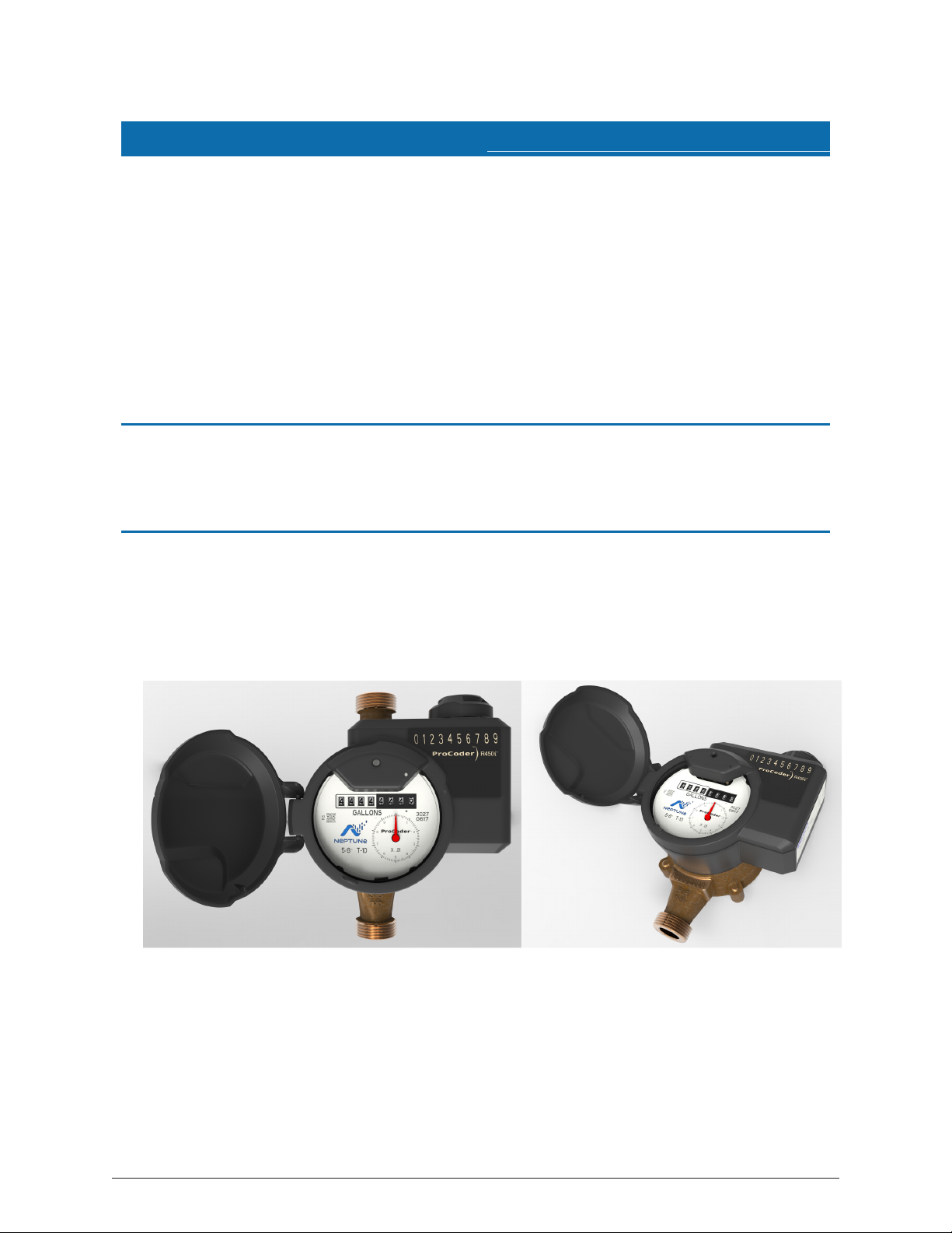
Figure 1 – ProCoder™)R450i™
Figure 2 – ProCoder™)R450i™ Dimensions
Figure 3 – ProCoder™)R450i™ Antenna Dimensions
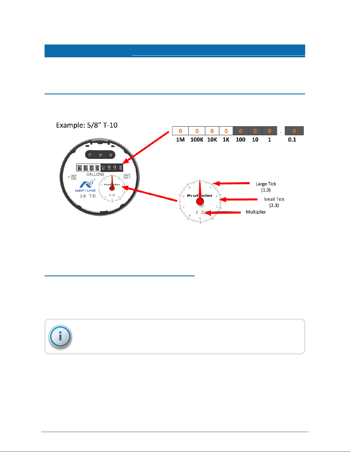
Figure 4 – ProCoder™ Display with Sweep Hand
Figure 5 – ProCoder™)R450i™ Installation
Figure 6 – ProCoder™)R450i™
Figure 7 – Through-the-Lid Antenna
Figure 8 – Locking the Nut on the Antenna
Figure 9 – Securing the Locking Nut
Figure 10 – Installation Complete
Figure 11 – Removing the Dust Cover
Figure 12 – Aligning the F Connector
Figure 13 – Connecting the Coaxial Cable
Figure 14 – Magnet Activation
Figure 15 – ProCoder™)R450i ™Config Email
Figure 16 – RSSI Validation Test Failed Email
Figure 17 – Register Test Failed Email 23
ProCoder™)R450i™ Installation and Maintenance Guide vii

This page intentionally left blank.
viii ProCoder™)R450i™ Installation and Maintenance Guide
Figures

Tables
3
3
3
5
5
8
9
20
21
22
27
27
28
31
31
Table 1 – Environmental Specifications
Table 2 – Functional Specifications
Table 3 – Dimensions and Weight
Table 4 – Recommended Tools
Table 5 – Recommended Materials
Table 6 – Possible Causes of Leaks
Table 7 – Checklist for Leaks
Table 8 – Config Email Subject Line Breakdown
Table 9 – Collector RSSI Uplink
Table 10 – ProCoder™)R450i™ RSSI Downlink
Table 11 – ProCoder™)R450i™ RSSI Downlink
Table 12 – Collector RSSI Uplink
Table 13 – Available Replacement Parts
Table 14 – Eighth-Digit Resolution by Register Size
Table 15 – ProCoder™)R450i™ Backflow Flags
Table 16 – ProCoder™)R450i™ Leak Status Flag 32
ProCoder™)R450i™ Installation and Maintenance Guide ix

This page intentionally left blank.
x ProCoder™)R450i™ Installation and Maintenance Guide
Tables
ProCoder™)R450i™ Installation and Maintenance Guide 1
Chapter 1: Product Description
This chapter provides a general description of the ProCoder™)R450i™ register. The
Neptune ProCoder)R450iis an integrated register that contains both the ProCoder™
and R450™ technologies in one register that collects meter reading data. It then
transmits the data the meter reader collects. A Neptune fixed network data collector
receives the data and stores it to download into the utility billing system for processing.
The ProCoder)R450ican be upgraded and configured. At the factory, serial numbers
are programmed into the ProCoder)R450i. Each device has a unique serial number /
identification number. Custom serial numbers are not available.
RF Protocol Error Detection
The RF protocol is comprised of a header, data packet, and an error detection
mechanism that reduces the erroneous data.
Low Battery RF Emissions
The ProCoder)R450idoes not produce out-of-band emissions under low battery
conditions. It is easy to install and requires a Federal Communications Commission
(FCC) license to operate. For information on obtaining an FCC license, refer to “FCC
Licensing,” in the R450™ System New Customer Guide.
Figure 1 – ProCoder™)R450i™

This page intentionally left blank.
Chapter 1: Product Description
2 ProCoder™)R450i™ Installation and Maintenance Guide

ProCoder™)R450i™ Installation and Maintenance Guide 3
Chapter 2: Specifications
This chapter provides the specifications for the ProCoder™)R450i™.
Specifications - ProCoder™)R450i™
The following tables give the environmental and functional specifications of the
ProCoder)R450i, including the dimensions and weight.
Environmental Specifications
Condition Description
Operating Temperature –10° to 149°F (–23° to 65°C)
Storage Temperature –40° to 185°F (–40° to 70°C)
Operating Humidity 0 to 100% condensing
Table 1 – Environmental Specifications
Functional Specifications
Specification Description
Register Reading Three to eight digits
ProCoder)R450iID 9 digits
Table 2 – Functional Specifications
Dimensions and Weight
Measurement Description
Dimensions Refer to Figure 2 on page 4.
Weight 1.57 lbs. (712.14 grams)
Table 3 – Dimensions and Weight
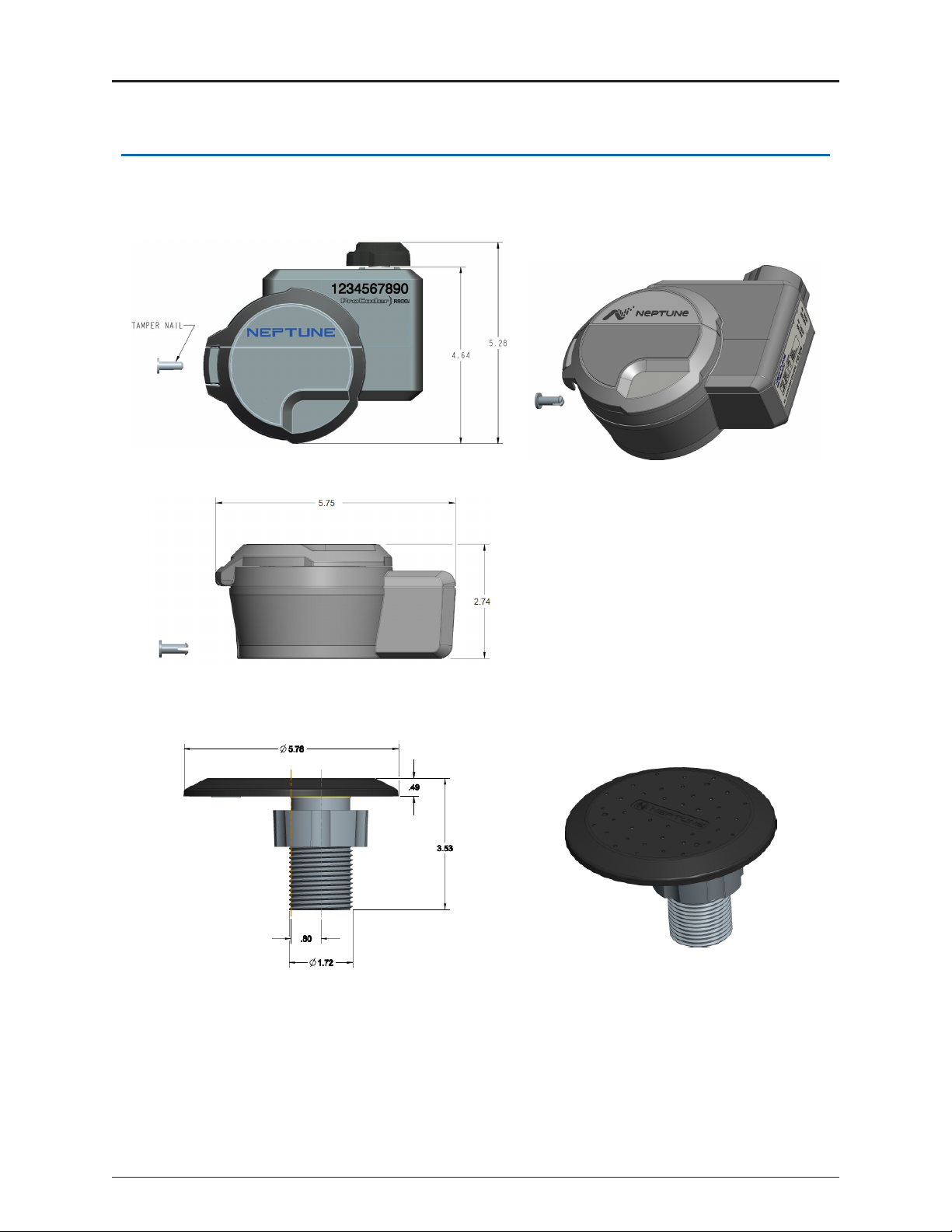
ProCoder™)R450i™ Dimensions
Figure 2 – ProCoder™)R450i™ Dimensions
Figure 3 – ProCoder™)R450i™ Antenna Dimensions
4 ProCoder™)R450i™Installation and Maintenance Guide
Chapter 2: Specifications

ProCoder™)R450i™ Installation and Maintenance Guide 5
Chapter 3: General Installation Guidelines
This chapter describes tools, materials, and general installation information for the
ProCoder™)R450i™.
Tools and Materials
"Recommended Tools" below show the recommended tools and materials you may
need to successfully install the ProCoder)R450i.
Some items may not apply to your specific installation, or the list may not contain all
required tools or materials.
Item Description / Recommendation Use
Tool Kit Contains standard tools including:
lScrewdrivers
lHammer
lPliers
l7/16 wrench (for the F
connector)
Various installation procedures
performed by the utility
Magnet 6 lbs. force
Part No: 12287-001
Activating the
ProCoder™)R450i™
Installation Tool Smart phone or cellular phone To receive emails
Table 4 – Recommended Tools
Item Description Use
Moisture Protection
Compound
Novagard sealant (Part No: 96018-
072)
Connecting the pit antenna to
the ProCoder)R450i
Site Work Order Documentation provided by your
utility
Receiving and recording
information about the work site
Table 5 – Recommended Materials

Safety and Preliminary Checks
Observe the following safety and preliminary checks before and during each
installation:
lVerify that you are at the location specified on the Site Work Order.
lVerify that the site is safe for you and your equipment.
lNotify the customer of your presence, and tell the customer that you need access to
the water meter.
lIf the Site Work Order does not have an MIU ID number on it, write in the ID
numbers of the MIU you are about to install.
lIf the Site Work Order already has an MIU ID number on it, verify that it matches the
ID numbers on the MIU you are about to install.
6 ProCoder™)R450i™Installation and Maintenance Guide
Chapter 3: General Installation Guidelines
ProCoder™)R450i™ Installation and Maintenance Guide 7
Chapter 4: Reading the ProCoder™)R450i™
This chapter provides information on reading the ProCoder™)R450i™.
How to Read
It is important to become familiar with the information available from the register.
Figure 4 – ProCoder™ Display with Sweep Hand
Sweep Hand Display
The sensitive sweep hand provides a visual representation of extreme low flows as well
as reverse flow. Depending on the size and type of ProCoder register, a specific
multiplier is present. This multiplier, along with the current position of the sweep hand,
provides additional digits of resolution that are especially useful for testing.
For further information on reading the ProCoder sweep hand, see the Product
Support Document entitled "How to Read the Neptune ProCoder™ Register."
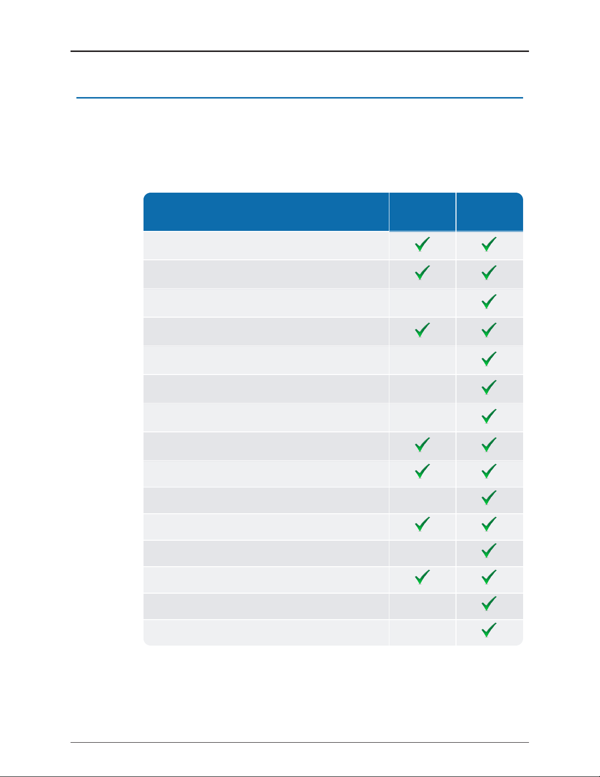
Common Causes of Leaks
If the leak indicator is flashing or continuously on, a possible leak may exist. Leaks can
result from various circumstances. To better help you identify a possible leak, the
following table contains some common causes of leaks.
Possible Causes of Leaks Intermittent
Leak
Continuous
Leak
Outside faucet, garden or sprinkler system leaking
Toilet valve not sealed properly
Toilet running
Faucet in kitchen or bathroom leaking
Ice maker leaking
Soaker hose in use
Leak between the water meter and the house
Washing machine leaking
Dishwasher leaking
Hot water heater leaking
Watering yard for more than eight hours
Continuous pet feeder
Water-cooled air conditioner or heat pump
Filling a swimming pool
Any continuous use of water for 24 hours
Table 6 – Possible Causes of Leaks
8 ProCoder™)R450i™Installation and Maintenance Guide
Chapter 4: Reading the ProCoder™)R450i™
Table of contents
Other Neptune Media Converter manuals


