Neptune E-CODER R900i Product manual

E-CODER®)R900i™
Installation and Maintenance Guide


E-CODER®)R900i™
Installation and Maintenance Guide

Copyright
This manual is an unpublished work and contains the trade secrets and
confidential information of Neptune Technology Group Inc., which are not to be
divulged to third parties and may not be reproduced or transmitted in whole or
part, in any form or by any means, electronic or mechanical for any purpose,
without the express written permission of Neptune Technology Group Inc. All
rights to design or inventions disclosed herein, including the right to
manufacture, are reserved to Neptune Technology Group Inc.
Neptune engages in ongoing research and development to improve and
enhance its products. Therefore, Neptune reserves the right to change product
or system specifications without notice.
Trademarks Used in this Manual
ProRead and E-CODER are a trademarks of Neptune Technology Group Inc.
R900 is a registered trademark of Neptune Technology Group Inc.
E-CODER)R900i is a trademark of Neptune Technology Group Inc. Other brands
or product names are the trademarks or registered trademarks of their
respective holders.
FCCNotice
This device complies with Part 15 of the FCC Rules. Operation is subject to the
following two conditions:
lThis device may not cause harmful interference.
lThis device must accept any interference received, including interference that
may cause undesired operation.
Note:This equipment has been tested and found to comply with the limits for a
Class B digital device, pursuant to Part 15 of the FCCRules. These limits are
designed to provide reasonable protection against harmful interference in a
residential installation. This equipment generates, uses, and can radiate radio
frequency energy, and if not installed and used in accordance with the
instructions, may cause harmful interference to radio communications.
However, there is no guarantee that interference will not occur in a particular
installation. If this equipment does cause harmful interference to radio or
television reception, which can be determined by turning the equipment off and
on, the user is encouraged to try to correct the interference by one or more of
the following measures:
lReorient or relocate the receiving antenna.
lIncrease the separation between the equipment and receiver.

RF Exposure Information
This equipment complies with the FCC RF radiation requirements for
uncontrolled environments. To maintain compliance with these requirements,
the antenna and any radiating elements should be installed to ensure that a
minimum separation distance of 20 cm is maintained from the general
population.
Changes or modifications not expressly approved by the party responsible for
compliance could void the users' authority to operate the equipment.
Professional Installation
In accordance with section 15.203 of the FCCrules and regulations, the Meter
Interface Unit (MIU) must be professionally installed by trained meter installers.
Changes or modifications not expressly approved by the party responsible for
compliance void the user's authority to operate the equipment.
Industry Canada
This Class B digital apparatus meets all requirements of theCanadian
Interference Causing Equipment Regulations. Operation is subject to the
following two conditions:
lThis device may not cause harmful interference.
lThis device must accept any interference received, including interference that
may cause undesired operation.
Cet appareillage numérique de la classe B répond à toutes les exigences de
l'interférence canadienne causant des règlements d'équipement. L'opération
est sujette aux deux conditions suivantes: (1) ce dispositif peut ne pas causer
l'interférence nocive, et (2) ce dispositif doit accepter n'importe quelle
interférence reçue, y compris l'interférence qui peut causer l'opération peu
désirée.

E-CODER®)R900i™
Installation and Maintenance Guide
Literature No. IME-CODER)R900i12.18
Part No. 12560-002
Neptune Technology Group Inc.
1600 Alabama Highway 229
Tallassee, AL 36078
Tel: (800) 633-8754
Fax: (334) 283-7293
Copyright © 2006 - 2018
Neptune Technology Group Inc.
All Rights Reserved.

Contents
1
2
Chapter 1: Product Description
E-CODER®)R900i™ Programming
Chapter 2: Specifications 3
3
Electrical Specifications
E-CODER)®R900i™ Dimensions 4
5
Chapter 3: Installing the E-CODER®)R900i™
Prior to Installation 5
Storage 5
Unpacking 5
Safety and Preliminary Checks 5
6
Site Selection
Installing the E-CODER®)R900i™6
New Meter Installation 6
Retrofit Meter Installation 7
7
8
Connecting the E-CODER®)R900i™ Through-the-Lid Antenna
Installing the Antenna
Attaching the Antenna to the MIU 9
Chapter 4: Activating and Reading the E-CODER®)R900i™11
Activating the LCD Using the Solar Panel 11
Read the Meter 12
Common Causes of Leaks 13
How to Tell if Water is in Use 14
What to Do if There is a Leak 14
If a Continuous Leak is Repaired 14
If an Intermittent Leak is Repaired 14
E-CODER®)R900
i
™Installation and Maintenance Guide v

Chapter 5: Data Logging Extraction 15
About Data Logging 15
Accessing Data Logging 15
Initiating RF Activated Data Logging 20
Sample Data Logging Graphs 22
Off Cycle Data Extraction 23
Belt Clip Transceiver 24
Chapter 6: Maintenance and Troubleshooting 25
Six- and Four-Wheel Encoders 25
Six-Wheel Encoder Normal Operation 25
Four-Wheel Encoder Normal Operation 25
Troubleshooting 26
Contact Information 26
By Phone 26
By Fax 27
By Email 27
Appendix 12: E-CODER®)R900i™ Flags 29
Description of Flags 29
Glossary 31
Index 33
vi E-CODER®)R900
i
™Installation and Maintenance Guide
Contents

Figures
1
4
4
7
8
8
8
9
9
9
10
11
11
15
16
16
17
17
18
18
19
19
20
20
21
21
Figure 1 – E-CODER®)R900i™
Figure 2 – Inside Dimensions
Figure 3 – Antenna Dimensions
Figure 4 – E-CODER®)R900i™ Antenna
Figure 5 – Insert the Antenna into the Pit Lid
Figure 6 – Locking Nut on Antenna
Figure 7 – Secure the Locking Nut
Figure 8 – Installation Complete
Figure 9 – Remove the Protective Cap and Gasket
Figure 10 – Align the F Connector
Figure 11 – Seat the Connection
Figure 12 – Solar Panel for the E-CODER®)R900i™
Figure 13 – Activating the E-CODER®)R900i™
Figure 14 – HHU Home Screen
Figure 15 – N_SIGHT® R900 Menu Screen
Figure 16 – Data Logger Option
Figure 17 – Reader ID Input
Figure 18 – HHU Time Confirmation
Figure 19 – Initialize RF Device
Figure 20 – Enter MIU ID
Figure 21 – Capture Button
Figure 22 – Unit of Measure and Meter Size
Figure 23 – Start Button
Figure 24 – E-CODER®)R900i™ Listens for Data
Figure 25 – E-CODER®)R900i™ Receives Data
Figure 26 – Graph Button
Figure 27 – Example Data Logging Graphs 22
E-CODER®)R900
i
™Installation and Maintenance Guide vii


Tables
3
12
13
22
26
29
Table 1 – E-CODER®)R900i™ Specifications
Table 2 – Icons and Displays
Table 3 – Causes of Leaks
Table 4 – Data Logging Graph Legend
Table 5 – Example Reading Values
Table 6 – Eighth Digit Resolution by Meter Size
Table 7 – E-CODER®)R900i™ Flags 29
E-CODER®)R900
i
™Installation and Maintenance Guide ix

This page intentionally left blank.
x E-CODER®)R900
i
™Installation and Maintenance Guide
Tables
E-CODER®)R900
i
™Installation and Maintenance Guide 1
Chapter 1: Product Description
This chapter provides a general description of the Neptune®E-CODER®)R900i™ register.
The E-CODER)R900iis an integrated register containing both the E-CODER®and R900®
technologies in one register that collects meter data. It then transmits the data that a meter
reader collects. A Neptune walk-by, mobile, R900 Gateway®fixed network data collection
system, or LoRa®fixed network collection system receives the data and stores it to
download into the utility billing system for processing.
The E-CODER)R900iis easily installed and operates within a radio frequency (RF) band which
does not require an operating license. The E-CODER)R900imeets FCC regulations part
15.247 allowing higher output power and greater range. It uses frequency-hopping spread
spectrum technology to avoid RF interference and enhance security. The transmitted data is
updated at 15-minute intervals and transmits a mobile message that includes the meter
reading data and the unique E-CODER)R900iID every 14-20 seconds. This allows the meter
to be read by a hand-held unit (HHU) or mobile data collections unit.
The E-CODER)R900ialso transmits a high-power fixed network message every seven and
one-half minutes on an interleaved basis to an R900 Gateway. If connected to a LoRa
network, the E-CODER)R900ican transmit a high-power fixed network message every three
hours on an interleaved basis.
The E-CODER)R900iis designed to offer advantages to utility organizations of all sizes:
lIncreases meter reading accuracy
lEliminates hard-to-read meters
lProtects utility liability by increasing meter reader safety
lRequires no external wiring or programming
lProvides enhanced eight-digit AMR meter reading
lProvides proactive customer service benefits (leak, tamper, and backflow detection)
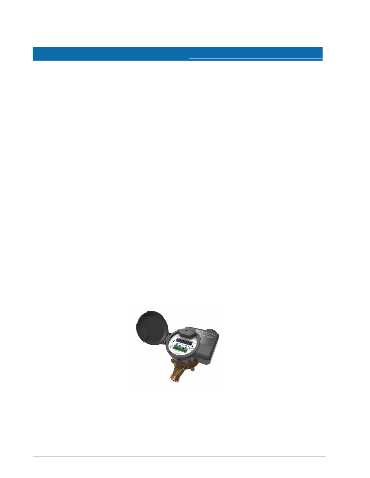
Figure 1 – E-CODER®)R900i™

E-CODER®)R900i™ Programming
The E-CODER)R900iis NOT field-programmable. At the factory, each of the following items is
programmed into the Meter Interface Unit (MIU):
lSerial number - each MIU is given a unique serial number / identification number
lMeter size and change gear information
2E-CODER®)R900
i
™Installation and Maintenance Guide
Chapter 1: Product Description

E-CODER®)R900
i
™Installation and Maintenance Guide 3
Chapter 2: Specifications
This chapter defines the specifications for the E-CODER®)R900i™.
Electrical Specifications
Specification Description
Power Lithium battery
Transmitter Specifications
Transmit Period lEvery 14 to 20 seconds – standard R900 mobile message
lEvery seven and one-half minutes – standard R900 fixed
network message
lEvery three hours – standard LoRa®fixed network message
Transmitter Channels l50 for R900 mobile and fixed
l64 for LoRa fixed network message
Channel Frequency 902-928 MHz
Output Power Meets FCC Part 15.247
FCC Verification Part 15.247
Environmental Conditions
Operating Temperature –22º to 149ºF (-30º to 65ºC)
Storage Temperature –40º to 158ºF (-40º to 70ºC)
Operating Humidity 0 to 100% Condensing (pit only)
Functional Specifications
Register Reading lEight digits (AMR)
lNine digits (Visual)
MIU ID lNine digits (R900 v5)
l10 digits (R900 v4)
Dimensions and Weight
Dimensions Refer to the figures on the following page.
Weight lInside – 1.39 lbs. (630.5 grams)
lPit – 1.62 lbs. (734.8) grams)
The following table defines the specifications for the E-CODER R900i.
Table 1 – E-CODER®)R900i™ Specifications

E-CODER)®R900i™ Dimensions
The following diagrams show both the inside and antenna dimensions for the
E-CODER)R900i.
Figure 2 – Inside Dimensions
Figure 3 – Antenna Dimensions
4E-CODER®)R900
i
™Installation and Maintenance Guide
Chapter 2: Specifications

E-CODER®)R900
i
™Installation and Maintenance Guide 5
Chapter 3: Installing the E-CODER®)R900i™
This chapter provides instructions for:
lStoring and unpacking the E-CODER®)R900i™
lPerforming preliminary tests
lVerifying materials
lSelecting a site
lInstalling the unit
Prior to Installation
This section defines how to unpack and store the E-CODER)R900iprior to installing it.
Storage
After receipt, inspect all shipping containers for damage, and inspect the contents of any
damaged cartons prior to storage.
After completing the inspection, store the cartons in a clean, dry environment. The unit
remains in sleep mode until it is exposed to light.
Unpacking
As with all precision electronic instruments, handle the E-CODER)R900icarefully; however,
no additional special handling is required. When shipped, the assembly is lying on its side.
You should lift the assembly out of the box by the meter main case.
After unpacking the E-CODER)R900i, inspect it for damage. If the E-CODER)R900iappears to
be damaged or proves to be defective upon installation, notify your Neptune Territory
Manager or Distributor. If one or more items requires reshipment, use the original
cardboard box and packing material.
Safety and Preliminary Checks
Observe the following safety and preliminary checks before and during each installation:
lVerify that you are at the location specified on the site work order.
lVerify that the site is safe for you and your equipment.
lNotify the customer of your presence, and tell the customer that you need access to the
water meter.
lIf the site work order does not have an MIU ID number on it, write in the ID number of the
MIU you are about to install. If the site work order already has an MIU ID number on it,
verify that it matches the ID number on the MIU you are about to install.

Site Selection
Installation and operation in moderate temperatures increase reliability and product life. See
“Environmental Conditions” on page3.
Follow these guidelines when selecting a location to install the E-CODER)R900i:
lInstall the unit in a vertical and upright position.
lClear all obstructions from the installation location.
Always follow your company's safety practices and installation guidelines when installing an
E-CODER. Never install a unit during a lightning storm or under excessively wet conditions.
Installing the E-CODER®)R900i™
Follow the steps in this section for a new or retrofit installation.
New Meter Installation
Follow these steps to perform a new meter installation.
1. Flush the service line prior to installation to remove debris in the line.
2. Place an electrical grounding strap on the service line, connecting the inlet and outlet
service lines on either side of the meter setting.
You must install inlet and outlet meter valves and couplings / setters if they are not already
present. Allow appropriate space in the line for the meter laying length and two coupling
gaskets. Align the pipe ends so that the coupling and meter threads can engage without
binding or cross-threading.
3. Before installing the meter, remove the thread protectors and spud caps. Be sure that no
debris enters the meter during installation.
Use caution; the meter threads are sharp.
4. Place the coupling gaskets inside the coupling nuts and set the meter in the line. Position
The meter horizontally with the register dial facing up. The direction of flow marked on
the meter must agree with the direction of water flow.
5. Start the coupling nuts by hand then use a wrench and tighten sufficiently to prevent
leakage. Be careful not to cross-thread the connections.
6E-CODER®)R900
i
™Installation and Maintenance Guide
Chapter 3: Installing the E-CODER®)R900i™

6. Open the meter outlet valve slowly. Open a down stream faucet and run enough water
to dissipate entrained air and flush the line. While the faucet is open, verify the meter is
operating correctly.
7. Turn off the faucet and check the meter installation for leaks. See "Activating and Reading
the E-CODER®)R900i™" on page11.
Retrofit Meter Installation
Follow these steps to perform a retrofit meter installation.
1. Use a punch / screwdriver and hammer to punch out the tamper-proof seal pin on the
existing register head.
2. Remove the existing register by twisting counter-clockwise.
3. Twist the new E-CODER)R900iregister head clockwise onto the meter body to install it.
4. Snap the new tamper-proof seal pin to secure the register to the meter body.
Connecting the E-CODER®)R900i™ Through-the-Lid Antenna
When ordering an external antenna for the E-CODER)R900iunit, Neptune recommends at
least a 6-foot cable to allow for easy removal of the pit lid when necessary.
Figure 4 – E-CODER®)R900i™ Antenna
E-CODER®)R900
i
™Installation and Maintenance Guide 7
Chapter 3: Installing the E-CODER®)R900i™

Installing the Antenna
Follow these steps to install the antenna for the E-CODER)R900i.
1. Insert the antenna cable and housing through the 1-3/4" hole in the meter pit lid.
Figure 5 – Insert the Antenna into the Pit Lid
2. Thread the locking nut onto the antenna, smooth end toward lid.
Figure 6 – Locking Nut on Antenna
3. Hand tighten the nut securely to the lid.
Figure 7 – Secure the Locking Nut
8E-CODER®)R900
i
™Installation and Maintenance Guide
Chapter 3: Installing the E-CODER®)R900i™
Other manuals for E-CODER R900i
1
Table of contents
Other Neptune Media Converter manuals


