Neptune E-Coder)R900i Product manual

FCC Part 15.247
Class II Permissive Change
Frequency Hopping Spread Spectrum Transmitter
FCC ID: P2SNTGECDR900Z
FCC Rule Part: 15.247
ACS Report Number: 05-0310-15C
Manufacturer: Neptune Technology Group, Inc.
Model: E-Coder R900
Installation Guide

E-Coder)R900i
Installation and Maintenance Guide
Neptune Technology Group Inc.
ARB
®
Water Revenue System
™


E-Coder)R900i
Installation and
Maintenance Guide

This manual is an unpublished work and contains the trade secrets and confidential information of Neptune Technology
Group Inc., which are not to be divulged to third parties and may not be reproduced or transmitted in whole or part, in
any form or by any means, electronic or mechanical for any purpose, without the express written permission of Nep-
tune Technology Group Inc. All rights to designs or inventions disclosed herein, including the right to manufacture, are
reserved to Neptune Technology Group Inc.
The information contained in this document is subject to change without notice. Neptune reserves the right to change
the product specifications at any time without incurring any obligations.
Trademarks used in this manual
E-Coder is a trademark of Neptune Technology Group Inc. R900 is a trademark of Neptune Technology Group Inc. Other
brands or product names are the trademarks or registered trademarks of their respective holders.
FCC Notice
This device complies with Part 15 of the FCC Rules. Operation is subject to the following two conditions: (1) this device
may not cause harmful interference, and (2) this device must accept any interference received, including interference
that may cause undesired operation.
NOTE: This equipment has been tested and found to comply with the limits for a Class B digital device, pursuant to
Part 15 of the FCC Rules. These limits are designed to provide reasonable protection against harmful interference in a
residential installation. This equipment generates, uses, and can radiate radio frequency energy and, if not installed
and used in accordance with the instructions, may cause harmful interference to radio communications. However, there
is no guarantee that interference will not occur in a particular installation. If this equipment does cause harmful inter-
ference to radio or television reception, which can be determined by turning the equipment off and on, the user is
encouraged to try to correct the interference by one or more of the following measures:
• Reorient or relocate the receiving antenna.
• Increase the separation between the equipment and receiver.
• Connect the equipment into an outlet on a circuit different from that to which the receiver is connected.
• Consult the dealer or an experienced radio/TV technician for help.
RF Exposure Information
This equipment complies with the FCC RF radiation requirements for uncontrolled environments. To maintain compli-
ance with these requirements, the antenna and any radiating elements should be installed to ensure that a minimum
separation distance of 20cm is maintained from the general population.
Professional Installation
In accordance with section 15.203 of the FCC rules and regulations, the MIU must be professionally installed by trained
utility meter installers. Changes or modifications not expressly approved by the party responsible for compliance could
void the user's authority to operate the equipment
Changes or modifications not expressly approved by the party responsible for compliance could void
the user's authority to operate the equipment.

Industry Canada
This Class B digital apparatus meets all requirements of the Canadian Interference Causing Equipment Regulations.
Operation is subject to the following two conditions: (1) this device may not cause harmful interference, and (2) this
device must accept any interference received, including interference that may cause undesired operation.
Cet appareillage numérique de la classe B répond à toutes les exigences de l'interférence canadienne causant des
règlements d'équipement. L'opération est sujette aux deux conditions suivantes: (1) ce dispositif peut ne pas causer
l'interférence nocive, et (2) ce dispositif doit accepter n'importe quelle interférence reçue, y compris l'interférence qui
peut causer l'opération peu désirée.
Copyright © 2005
Neptune Technology Group Inc.
All Rights Reserved.
E-Coder)R900i Installation and Maintenance Guide
Literature No. IM E-Coder0R900i10.05
Part No. XXXXXX-001
Neptune Technology Group Inc.
1600 Alabama Highway 229
Tallassee, AL 36078
Tel: (334) 283-6555
Fax: (334) 263-7299


Contents
E-Coder)R900iBasement and Pit Installation and Maintenance Guide v
1Product Description
E-Coder)R900iProgramming . . . . . . . . . . . . . . . . . . . . . . . . . . . . . . . . . . . . . . . . . . . . . . . . . . . . . . . . . . . . 2
RF Protocol Error Detection . . . . . . . . . . . . . . . . . . . . . . . . . . . . . . . . . . . . . . . . . . . . . . . . . . . . . . . . . . . . . 2
RF Frequency Control Algorithm . . . . . . . . . . . . . . . . . . . . . . . . . . . . . . . . . . . . . . . . . . . . . . . . . . . . . . . . . 2
RF Transmission Period and Randomness . . . . . . . . . . . . . . . . . . . . . . . . . . . . . . . . . . . . . . . . . . . . . . . . . . 2
2Specifications
Electrical Specifications . . . . . . . . . . . . . . . . . . . . . . . . . . . . . . . . . . . . . . . . . . . . . . . . . . . . . . . . . . . . . . . . . . . 3
Transmitter Specifications . . . . . . . . . . . . . . . . . . . . . . . . . . . . . . . . . . . . . . . . . . . . . . . . . . . . . . . . . . . . . 3
Environmental Conditions . . . . . . . . . . . . . . . . . . . . . . . . . . . . . . . . . . . . . . . . . . . . . . . . . . . . . . . . . . . . . . 3
Functional Specifications . . . . . . . . . . . . . . . . . . . . . . . . . . . . . . . . . . . . . . . . . . . . . . . . . . . . . . . . . . . . . . 3
Dimensions and Weight . . . . . . . . . . . . . . . . . . . . . . . . . . . . . . . . . . . . . . . . . . . . . . . . . . . . . . . . . . . . . . . 3
3General Installation Guidelines
Tools and Materials . . . . . . . . . . . . . . . . . . . . . . . . . . . . . . . . . . . . . . . . . . . . . . . . . . . . . . . . . . . . . . . . . . . 5
Safety and Preliminary Checks . . . . . . . . . . . . . . . . . . . . . . . . . . . . . . . . . . . . . . . . . . . . . . . . . . . . . . . . . . 5
4Activating and Reading the E-Coder)R900i
How to Activate LCD Using the Light Sensor . . . . . . . . . . . . . . . . . . . . . . . . . . . . . . . . . . . . . . . . . . . . . . . 6
How to Read . . . . . . . . . . . . . . . . . . . . . . . . . . . . . . . . . . . . . . . . . . . . . . . . . . . . . . . . . . . . . . . . . . . . . . . . 6
Common Causes of Leaks . . . . . . . . . . . . . . . . . . . . . . . . . . . . . . . . . . . . . . . . . . . . . . . . . . . . . . . . . . . . . . 7
How to tell if water is in use . . . . . . . . . . . . . . . . . . . . . . . . . . . . . . . . . . . . . . . . . . . . . . . . . . . . . . . . . . . . 9
What to Do if There is a Leak . . . . . . . . . . . . . . . . . . . . . . . . . . . . . . . . . . . . . . . . . . . . . . . . . . . . . . . . . . . 9
If Continuous Leak is Repaired . . . . . . . . . . . . . . . . . . . . . . . . . . . . . . . . . . . . . . . . . . . . . . . . . . . . . . . . . . 9
If Intermittent Leak is Repaired . . . . . . . . . . . . . . . . . . . . . . . . . . . . . . . . . . . . . . . . . . . . . . . . . . . . . . . . . . 9
Software . . . . . . . . . . . . . . . . . . . . . . . . . . . . . . . . . . . . . . . . . . . . . . . . . . . . . . . . . . . . . . . . . . . . . . . . . . . 9

Contents
vi E-Coder)R900iBasement and Pit Installation and Maintenance Guide
5Installing the Basement Version
Prior to Installation . . . . . . . . . . . . . . . . . . . . . . . . . . . . . . . . . . . . . . . . . . . . . . . . . . . . . . . . . . . . . . . . . . . . . . 10
Storage . . . . . . . . . . . . . . . . . . . . . . . . . . . . . . . . . . . . . . . . . . . . . . . . . . . . . . . . . . . . . . . . . . . . . . . . . . . 10
Unpacking . . . . . . . . . . . . . . . . . . . . . . . . . . . . . . . . . . . . . . . . . . . . . . . . . . . . . . . . . . . . . . . . . . . . . . . . . 10
Installing the E-Coder)R900iBasement Version MIU . . . . . . . . . . . . . . . . . . . . . . . . . . . . . . . . . . . . . . . . . . . . 11
New Meter Installation: . . . . . . . . . . . . . . . . . . . . . . . . . . . . . . . . . . . . . . . . . . . . . . . . . . . . . . . . . . . . . . 11
Retrofit Meter Installation: . . . . . . . . . . . . . . . . . . . . . . . . . . . . . . . . . . . . . . . . . . . . . . . . . . . . . . . . . . . . 12
Testing the E-Coder)R900iBasement Installation . . . . . . . . . . . . . . . . . . . . . . . . . . . . . . . . . . . . . . . . . . 13
Completing the E-Coder)R900iBasement Installation . . . . . . . . . . . . . . . . . . . . . . . . . . . . . . . . . . . . . . . 13
Testing the R900 MIU Installation . . . . . . . . . . . . . . . . . . . . . . . . . . . . . . . . . . . . . . . . . . . . . . . . . . . . . . . . . . 14
Checklist . . . . . . . . . . . . . . . . . . . . . . . . . . . . . . . . . . . . . . . . . . . . . . . . . . . . . . . . . . . . . . . . . . . . . . . . . . . . . . 15
6Installing the Pit Version
Prior to Installation . . . . . . . . . . . . . . . . . . . . . . . . . . . . . . . . . . . . . . . . . . . . . . . . . . . . . . . . . . . . . . . . . . . . . . 16
Storage . . . . . . . . . . . . . . . . . . . . . . . . . . . . . . . . . . . . . . . . . . . . . . . . . . . . . . . . . . . . . . . . . . . . . . . . . . . 16
Unpacking . . . . . . . . . . . . . . . . . . . . . . . . . . . . . . . . . . . . . . . . . . . . . . . . . . . . . . . . . . . . . . . . . . . . . . . . . 16
Installing the E-Coder)R900iPit Version MIU . . . . . . . . . . . . . . . . . . . . . . . . . . . . . . . . . . . . . . . . . . . . . . . . . . 17
New Meter Installation: . . . . . . . . . . . . . . . . . . . . . . . . . . . . . . . . . . . . . . . . . . . . . . . . . . . . . . . . . . . . . . 17
Retrofit Meter Installation: . . . . . . . . . . . . . . . . . . . . . . . . . . . . . . . . . . . . . . . . . . . . . . . . . . . . . . . . . . . . 18
Testing the E-Coder)R900iPit Installation . . . . . . . . . . . . . . . . . . . . . . . . . . . . . . . . . . . . . . . . . . . . . . . . 19
Completing the E-Coder)R900iPit Installation . . . . . . . . . . . . . . . . . . . . . . . . . . . . . . . . . . . . . . . . . . . . . 19
7Maintenance and Troubleshooting
Replacing the MIU Battery (E-Coder)R900iPit Version) . . . . . . . . . . . . . . . . . . . . . . . . . . . . . . . . . . . . . . . . . . 20
Removing the Battery Assembly: . . . . . . . . . . . . . . . . . . . . . . . . . . . . . . . . . . . . . . . . . . . . . . . . . . . . . . . 20
Upgrading the R900 Antenna. . . . . . . . . . . . . . . . . . . . . . . . . . . . . . . . . . . . . . . . . . . . . . . . . . . . . . . . . . . . . . . 23
Contact Information . . . . . . . . . . . . . . . . . . . . . . . . . . . . . . . . . . . . . . . . . . . . . . . . . . . . . . . . . . . . . . . . . . . . . 24
Glossary
Index

E-Coder)R900iBasement and Pit Installation and Maintenance Guide vii
Figures
Figure Title Page
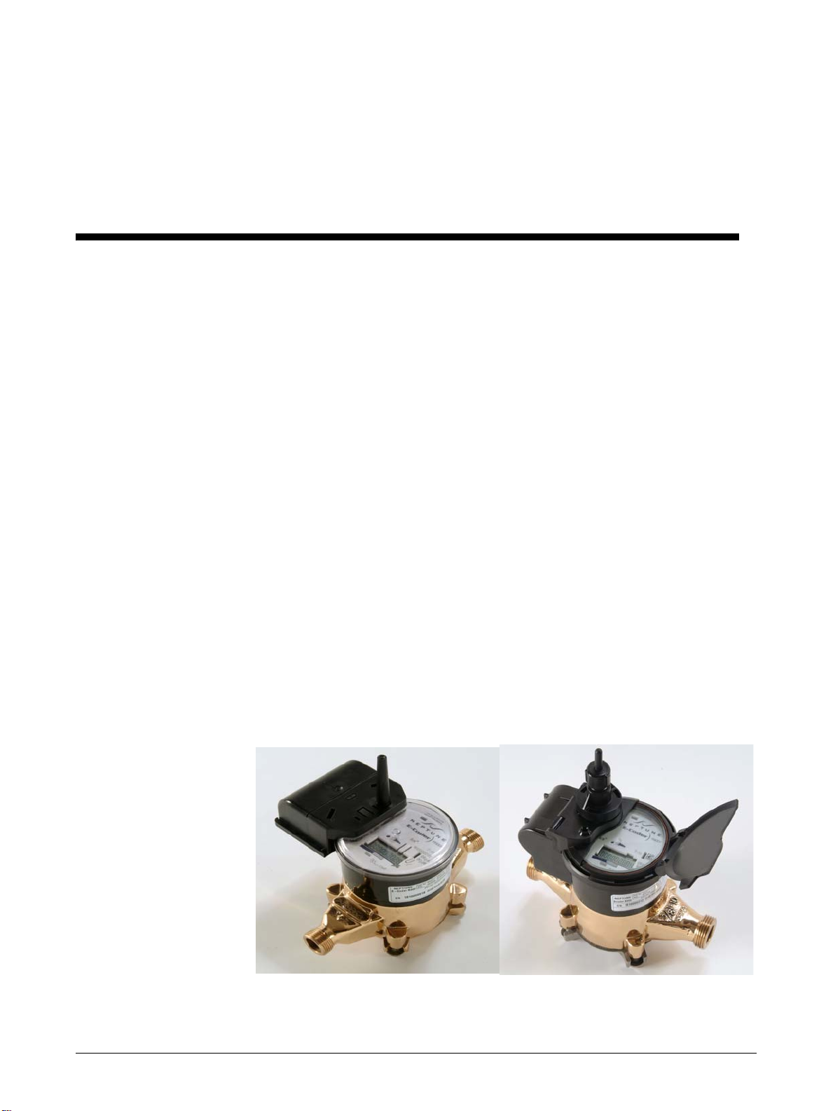
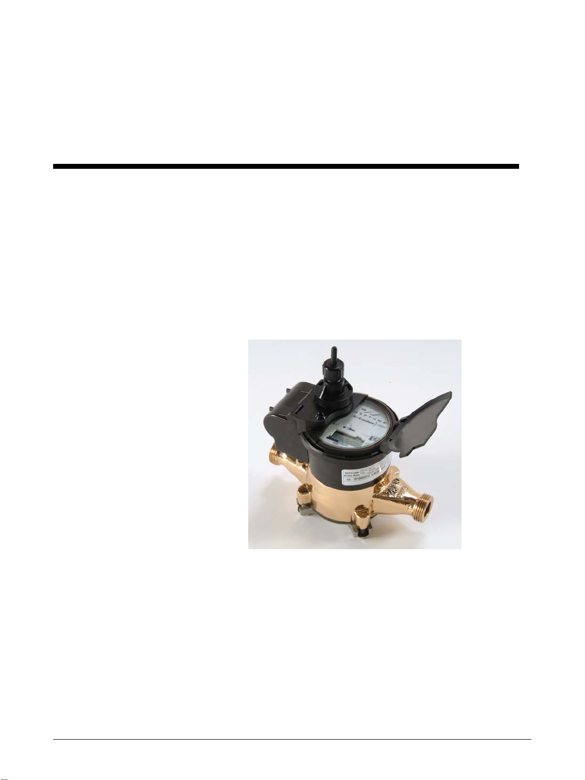
1 E-Coder)R900iBasement and Pit Versions . . . . . . . . . . . . . . . . . . . . . . . . . . . . . . . . . . . . . . . . . . . . . . . . . . . . . . . 1
2 E-Coder)R900iDiagram. . . . . . . . . . . . . . . . . . . . . . . . . . . . . . . . . . . . . . . . . . . . . . . . . . . . . . . . . . . . .4
3 E-Coder)R900iBasement and Pit Version Dimensions . . . . . . . . . . . . . . . . . . . . . . . . . . . . . . . . . . . . . . . . . . . . 4
4 Activating the LCD . . . . . . . . . . . . . . . . . . . . . . . . . . . . . . . . . . . . . . . . . . . . . . . . . . . . . . . . . . . . . . . . . . . . . . . . . . . . . . 6
5 E-Coder)R900iBasement Installation . . . . . . . . . . . . . . . . . . . . . . . . . . . . . . . . . . . . . . . . . . . . . . . . . . . . . . . . . . . 10
6 E-Coder)R900iPit Installation . . . . . . . . . . . . . . . . . . . . . . . . . . . . . . . . . . . . . . . . . . . . . . . . . . . . . . . . . . . . . . . . . . 16
7 Screwdriver in Tamper Nail . . . . . . . . . . . . . . . . . . . . . . . . . . . . . . . . . . . . . . . . . . . . . . . . . . . . . . . . 20
8 Sliding Battery over Antenna . . . . . . . . . . . . . . . . . . . . . . . . . . . . . . . . . . . . . . . . . . . . . . . . . . . . . . . 20
9 Pushing in New Tamper Nail . . . . . . . . . . . . . . . . . . . . . . . . . . . . . . . . . . . . . . . . . . . . . . . . . . . . . . . 21
10 Screwdriver in Seal Pin . . . . . . . . . . . . . . . . . . . . . . . . . . . . . . . . . . . . . . . . . . . . . . . . . . . . . . . . . . . . . . . . . . . . . . . . . .21
11 Removing Battery from Hinges. . . . . . . . . . . . . . . . . . . . . . . . . . . . . . . . . . . . . . . . . . . . . . . . . . . . . . . . . . . . . . . . . . . 21
12 Cutting the Battery Wires. . . . . . . . . . . . . . . . . . . . . . . . . . . . . . . . . . . . . . . . . . . . . . . . . . . . . . . . . . . . . . . . . . . . . . . .22
13 Using Scotchlok to Splice Wires . . . . . . . . . . . . . . . . . . . . . . . . . . . . . . . . . . . . . . . . . . . . . . . . . . . . . . . . . . . . . . . . .22
14 Feeding Antenna Cable . . . . . . . . . . . . . . . . . . . . . . . . . . . . . . . . . . . . . . . . . . . . . . . . . . . . . . . . . . . . . . . . . . . . . . . . . .23
15 Placing Washer on MIU . . . . . . . . . . . . . . . . . . . . . . . . . . . . . . . . . . . . . . . . . . . . . . . . . . . . . . . . . . . . . . . . . . . . . . . . .23
16 Connecting the Coaxial Cable. . . . . . . . . . . . . . . . . . . . . . . . . . . . . . . . . . . . . . . . . . . . . . . . . . . . . . . . . . . . . . . . . . . .24
17 Connecting the Plastic Connector . . . . . . . . . . . . . . . . . . . . . . . . . . . . . . . . . . . . . . . . . . . . . . . . . . . . . . . . . . . . . . . .24

viii E-Coder)R900iBasement and Pit Installation and Maintenance Guide
Notes:
Figures

E-Coder)R900iBasement and Pit Installation and Maintenance Guide ix
Tables
Table Title Page
1 Recommended Tools . . . . . . . . . . . . . . . . . . . . . . . . . . . . . . . . . . . . . . . . . . . . . . . . . . . . . . . . . . . . . . . . . . . . . 5
2 Icons and Displays . . . . . . . . . . . . . . . . . . . . . . . . . . . . . . . . . . . . . . . . . . . . . . . . . . . . . . . . . . . . . . . . . . . . . . . . 6
3 Possible Leaks . . . . . . . . . . . . . . . . . . . . . . . . . . . . . . . . . . . . . . . . . . . . . . . . . . . . . . . . . . . . . . . . . . . . . . . . . . . . 7
4 Checklist for Leaks . . . . . . . . . . . . . . . . . . . . . . . . . . . . . . . . . . . . . . . . . . . . . . . . . . . . . . . . . . . . . . . . . . . . . . . 9
5 Checklist for Before Leaving Site . . . . . . . . . . . . . . . . . . . . . . . . . . . . . . . . . . . . . . . . . . . . . . . . . . . . . . . . . 15

x E-Coder)R900iBasement and Pit Installation and Maintenance Guide
Notes:
Tables
E-Coder)R900iBasement and Pit Installation and Maintenance Guide 1
1 Product Description
This section provides a general description of the E-Coder)R900iregister (subse-
quently referred to E-Coder)R900i). The E-Coder)R900iby Neptune is an inte-
grated register that contains both the E-Coder and R900 technologies in one
register that collects meter reading data. It then transmits the data for collection by
the meter reader. A walk-by handheld, mobile unit, or fixed network receives the
data and stores it to be downloaded into the utility billing system for processing.
The E-Coder)R900iis easily installed and operates within an RF band which does
not require an operating license. The E-Coder)R900imeets FCC regulations part
15.247, allowing higher output power and greater range. The E-Coder)R900iuses
frequency-hopping spread spectrum technology to avoid RF interference and
enhance security. The transmitted data is updated at 15 minute intervals and is
transmitted every 14 seconds. A unique 10-digit MIU ID is included in the transmis-
sion of data. This allows the meter to be read by a walk-by handheld, mobile or
fixed network data collection units. The E-Coder)R900iis designed to offer advan-
tages to utility organizations of all sizes:
• Increases meter reading accuracy
• Eliminates "hard to read" meters
• Protects utility liability by increasing meter reader safety
• Requires no external wiring or programming
• Provides enhanced 8-digit AMR meter reading
• Provides proactive customer service benefits (leak, tamper and backflow
detection)
Figure 1 E-Coder)R900iBasement and Pit Versions

Product Description
2 E-Coder)R900iBasement and Pit Installation and Maintenance Guide
E-Coder)R900iProgramming
The E-Coder)R900iis NOT field-programmable. At the factory, each of the follow-
ing items is programmed into the MIU:
• Serial number - Each MIU is given a unique 10-digit serial number/identifica-
tion number.
• Time between MIU transmissions - The time between MIU transmissions is set
for approximately 14 seconds. Custom time is not available.
RF Protocol Error Detection
The RF protocol is comprised of a header, data packet, and an error detection
mechanism that reduces the erroneous data.
RF Frequency Control Algorithm
The MIU's frequency-hopping, spread-spectrum has a sequence of at least 50 differ-
ent channels for transmitting data. Associated with the 50 channels are 50 frequen-
cies that can be pre-selected in a pseudo random manner. These 50 frequencies are
coded into the software.
RF Transmission Period and Randomness
The random period generation uses the same random seed created for the channel
definition to generate the transmission randomness. The randomness algorithm is
defined so that no two consecutive transmissions from two MIUs will interfere
with one another.

E-Coder)R900iBasement and Pit Installation and Maintenance Guide 3
2 Specifications
This section provides you with the specifications for the E-Coder)R900i.
Electrical Specifications
Transmitter Specifications
Environmental Conditions
Functional Specifications
Dimensions and Weight
Power Lithium battery
Transmit Period Every 14 seconds
Transmitter Channels 50
Channel Frequency 910-920 MHz
Output Power Meets FCC Part 15.247
FCC Verification Part 15.247
Operating Temperature -22° to 149°F (-30° to 65°C)
Storage Temperature -40° to 158°F (-40° to 70°C)
Operating Humidity 0 to 95% Condensing
Register Reading 8 digits
MIU ID 10 digits
Dimensions Refer to Figure 3
Weight 1.08 lbs. (490 grams)

Specifications
4 E-Coder)R900iBasement and Pit Installation and Maintenance Guide
Figure 2 E-Coder)R900i Diagram
Figure 3 E-Coder)R900iBasement and Pit Version Dimensions

E-Coder)R900iBasement and Pit Installation and Maintenance Guide 5
3 General Installation Guidelines
This section describes tools, materials, and general installation information for the
E-Coder)R900i.
Tools and Materials
Tables 1 and 2 show the recommended tools and materials you may need to suc-
cessfully install the E-Coder)R900ior to replace the MIU’s internal battery.
Safety and Preliminary Checks
Observe the following safety and preliminary checks before and during each instal-
lation:
• Verify that you are at the location specified on the Site Work Order.
• Verify that the site is safe for you and your equipment.
• Notify the customer of your presence and tell the customer that you will need
access to the water meter.
• If the Site Work Order does not have an MIU ID number on it, write in the ID
number(s) of the MIU you are about to install. If the Site Work Order already
has an MIU ID number on it, verify that it matches the ID numbers on the MIU
you are about to install.
Some items may not apply to your specific installation or the list may not contain all required tools
or materials.
Table 1 Recommended Tools
Item Description/ Recommendation Use
Tool Kit Contains standard tools including:
• Screwdrivers
•Hammer
• Pliers
Various installation procedures
performed by the utility
Flashlight Activating the MIU
E-Coder)R900iBasement and Pit Installation and Maintenance Guide 6
4 Activating and Reading the E-Coder)R900i
How to Activate LCD Using the Light Sensor
The light sensor is recessed under the small round hole near the center of the dial
face. The hole is marked with a light bulb graphic (see figure). The light sensor
activates the LCD display for several minutes when the unit is exposed to a light
source. For example, a unit mounted in the basement would turn on the LCD for
several minutes after the room light is turned on. A unit mounted in an outside pit
would turn on the LCD for several minutes after the pit lid is opened exposing the
unit to daylight. If the LCD is currently off, the LCD may be reactivated by covering
the dial plate with your hand for about two seconds. In bright sunlight, it may be
necessary to close the cover or the pit lid momentarily. If the LCD does not reacti-
vate as expected, try shining a flashlight on the light sensor.
Figure 4 Activating the LCD
How to Read
It is important to become familiar with the information available from the meter.
To identify this information the following icons and displays are helpful.

Activating and Reading the E-Coder)R900i
E-Coder)R900iBasement and Pit Installation and Maintenance Guide 7
Table 2 Icons and Displays
Solar Cell, located at the top of the E-Coder, supplies the power for the
register. It is activated by light.
Light Sensor, recessed under the small hole near the center of the face-
plate of the E-Coder)R900i, supplies the power for the LCD panel (light
activated).
Flow/Leak Indicator shows the direction of flow through the meter:
ON Water in use
OFF Water not in use.
Flashing Water is running slowly/low flow indica-
tion.
Leak indicator displays a possible leak:
OFF No leak indicated.
Flashing Intermittent leak indicated. Water used
during at least 1/2 of the 15-minute inter-
vals in the last 24 hours (96 15-minute
intervals in a 24-hour period).
Continuous
ON
Continuous leak indicated. Water used
during all 15-minute intervals in the last 24
hours.
Nine-digit LCD displays the meter reading
in billing units of gallons or cubic feet.
Last three digits Testing units used for meter testing.
Fifth & Sixth
reading
digits
Reading units.
First four digits Typical billing digits.
Table of contents
Other Neptune Transmitter manuals


Popular Transmitter manuals by other brands


elero
elero COM Series INFORMATION FOR USE

rojaflex
rojaflex WSR-1 Original assembly and operating instructions

City Theatrical
City Theatrical Multiverse 5911 user manual

Gatekeeper Systems
Gatekeeper Systems Long Range Transmitter 2 user manual

BWI Eagle
BWI Eagle AIR-EAGLE XLT Product information bulletin

Williams Sound
Williams Sound IR T2 Wiring guide