manuals.online logo
Brands
  1. Home
  2. •
  3. Brands
  4. •
  5. Evikon
  6. •
  7. Transmitter
  8. •
  9. Evikon E2618-H2S User manual

Evikon E2618-H2S User manual

Hydrogen sulfide transmitter E2618-H2S is a member of new PluraSens® family of
multifunctional measurement instruments. Applications include sewerage systems,
labs, industrial premises and other confined spaces where potentially toxic
concentration of hydrogen sulfide can accumulate.
The instrument utilises digital fully calibrated and temperature compensated
electrochemical gas sensor with excellent repeatability, stability and long lifetime.
The transmitter is supplied either in duct-mount or wall-mount version. For the
wall-mount version the range of remote probe options is available.
Two freely configurable 4-20 mA or 0-10 V analog outputs can be used to connect
the transmitter to secondary instruments. RS485 interface with industry-standard
Modbus RTU protocol allows direct Fieldbusnetworking of the transmitter.
Safety requirements
Always adhere to the safety provisions applicable in the country of use.
Do not perform any maintenance operation with the power on. Do not let water or
foreign objects inside the device.
Operating conditions
The device should be used in explosion-safe (non ATEX -rated) indoor areas,
without aggressive gases in the atmosphere. Allowed conditions are:
– temperature in the range of -30...+50 °C
– relative humidity in the range of 15...90%
– atmospheric pressure in the range of 80...120 kPa.
Installation and connection
1. Duct mount version: Connect the sensor probe to the device main unit. Make
sure that the connections are tightened properly.
Cut a 25 mm diameter hole in the air ductat the chosen mounting place.Fix the 25
mm cable gland in the hole. Pass the sensor probe through the gland, adjust it to
the appropriate depth and tighten the gland’s screw. Unscrew four lid screws and
detach the lid from the instrument.
Wall mount version: Unscrew four lid screws and detach the lid from the
instrument. Fix the transmitter through mounting holes by screws.
The device should be mounted in proximity to potential H2S sources and away
from ventilation holes or dead-air spaces such as corners. Locate the sensor at
30...80cm from the floor, pointing downwards. Recommended coverage area for
each transmitter is 50..100 m2(4...5,5 m radius).
2. Plug the power cable and connectthe analog outputs and/or digital interface
terminals to the relevant devices according to the connection diagram.
Make certain that the cable gland is properly tightened to ensure the conformity to
IP65 protection class.
The screwless quick connect spring terminals on the E2618 series devices are
suitable for a wide range of wires with cross-section 0,2...1,5 mm2. The
recommended wire stripping length is 8...9 mm. Push the spring loaded terminal
lever, insert the wire end into terminal hole and release the lever.
Use twisted pair cable, e.g. LiYY TP 2×2×0,5 mm2or CAT 5, to connect the device
to RS485 network. Use one pair for A and B wires and the second pair for common
0 V and power +U wires. to connect the transmitter to Fieldbus network. Respect
polarity. Overall length of all connections via RS485 interface should not exceed
1200 m.
Place the lid back and tighten it with the four screws.
The type of each analog output can be independently changed between 4-20 mA
and 0-10 V with jumpers J1 (OUT1) and J2 (OUT2).
With closed jumper the output is 0-10V, with open jumper the outputis 4-20 mA.
By default both outputs OUT1 and OUT2 are assigned to gas concentration. The
device has built-in temperature sensor wich may be connected to any of the
outputs.
The output assignments and scales can bechanged by Modbus commands.
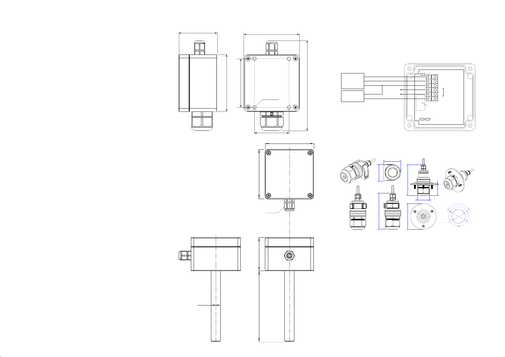
Sensor probe handling
The wall mount version of the transmitter is available with remote probe (see
drawing for dimentions).
36
77
Ø35...36 Ø50
120°
Ø65 80
327
Ø34 max
Hole
35
The remote probe is connected to the main unit with shielded cable. The
connection cable length options are 2,5 mor 5 m.
The sensor probes of all types are equipped with a hydrophobic microporous
PTFE filter to protect the sensor from dust, dirt and water drops. The round filter is
snap-fitted and may be replaced if it gets strongly contaminated.
To replace the PTFE filter, carefully hook the filter near it’s edge with a small flat
screwdriver and pull it off. Place a new filter onto the sensor opening and press it
to snap into the groove.
NB! Never stab or press the filter near its center where the sensor is located sinse
this may damage the sensor.
The recommended orientation of sensor probe is vertical with the sensor tip
pointing downwards. This prevents possible accumulation of condensed water on
the sensor protection filter. The horizontal orientation is also suitable. Avoid upward
position of the sensor tip.
Emergency mode
The current outputs ofthe transmitter may be programmed via Modbus commands
to signal if the connection with the sensor is lost. The signal may be set to 3,8 mA
or 21,5 mA. See the table of Modbus registers for more information.
4-20 mA/ 0-10 V
4-20 mA/ 0-10 V
0V / GND
0V
Controller
Power Supply
Input 1
Input 2 OUT1
OUT2
0V
A
BRS485
+U
J1 J2
Fieldbus
Sensor module
+12 V
J3
Dimensions of the E2618 wall-mount version
Dimensions of the E2618 duct mount version
Ø4 mm
55 80
130
82
50
70
55
115
M16
82
80
Ø16
Return to default settings
To reset the device’s Slave ID, baudrate and sbit number to factory settings,
proceed as follows:
1. De-energize the device
2. Connect the J3 jumper
3. Turn on the device
4. De-energize the device
5. Disconnect the J3 jumper
6. Turn on the device
Calibration
E2618-H2S has been calibrated by Manufacturer with standard gas mixture before
delivery. The electrochemical gas sensor exhibits high stability and ~2 year
lifetime. However, as the gas sensor is directly exposed to environment, the
instrument requires a field recalibration with a portable calibration kit at leastevery
6 month. Please contact your distributor for moreinformation.
Delivery set
– Hydrogen suldfide transmitter E2618-H2S or E2618-H2S-DM
– Mounting accessories:
4 screws with plastic dowels for wall mount version
25mm cable gland for duct mount version.
fixing clamp for remote probe versions
Warranty
This product is warranted to be free from defects in material and workmanship for a
period of one year from the date of original sale. During this warranty period
Manufacturer will, at its option, either repair or replace product that proves to be
defective. This warranty is void if the product has been operated in conditions
outside ranges specified by Manufacturer or damaged by customer error or
negligence or if there has been an unauthorized modification.
E2618-H2S_UM_EN Rev 04.05.2016
General technical data
Sensor type long-life electrochemical gas sensor
Detected gase Hydrogen sulfide H2S
Calibration Hydrogen sulfide H2S
Sampling method diffusion
Detection range options standard 0...100 ppm(500 ppm peak) H2S
high 0...1000 ppm (10 000 ppmpeak) H2S
Resolution 0,1 / 1 ppm H2S
Accuracy < 1 ppm H2S
Gas unit 1 ppm / 0.1 ppm
Signal update every 1 second
Response time < 30 seconds
Self-diagnostics full functionality check at start-up
Power supply 11...30 VDC,
Power consumption < 2 W
Analog outputs 2 × 4-20 mA / 0-10 V, user settable, freely configurable
Digital interface RS485, Modbus RTU protocol
no galvanic isolation, common-mode voltage -7...+12 V,
Cable connections screwless spring loaded terminals
Enclosure grey ABS, wall mount, protection class IP65
Dimensions H82 × W80 × D55 mm
Operating environment industrial indoor and outdoor locations
Operating conditions -30...+50 °C, 15...90 %RH
Maintenance interval 6 month
Sensor lifetime 2 years
CE marking meets 2014/30/EU and EN61326-1requirements
RS485 communication interface
Databits: 8
Parity: none
Stop bits: 1 or 2
Protocol: Modbus RTU
Supported Modbus functions:
03 - read multiple registers
06 - write single register
Communication parameters
Parameter Permitted values Default
Supported
baudrates 1200, 2400, 4800, 9600, 19200,
38400, 57600 9600
Data bits 8 8
Parity none none
Stop bits 1, 2 1
Protocol Modbus RTU
Modbus functions 03 - read multiple registers
06 - write single register
Error codes 01- illegalfunction
02- illegaldata address
03- illegaldata value
04- slave devicefailure
(details of last error 04 can beread from register 0x0008)
Evikon MCI OÜ Riia 185, Tartu [email protected]
Tel.:+372 733 6310 51014 Estonia www.evikon.eu
Hydrogen sulfide transmitter
E2618-H2S
User manual
E2618 series Modbus holding registers
Register addresses are shown 0-based, Addr in hexadecimal, Reg in decimal format.
Modbus holding register numbers MHR are shown in decimal 1-based format, and may be addressed either from 00001 or 40001 base.
Addr Reg / MHR RW Description Supported values (dec) Default
0x0001 1 / 40002 R Hardware version -
0x0002 2 / 40003 R Software version -
0x0003 3 / 40004 R Product serial number 1...65535 -
0x0004 4 / 40005 RW Slave ID (net address) * 1...247 ** 1
0x0005 5 / 40006 RW Baudrate * 1200, 2400, 4800, 9600, 19200, 38400, 57600 9600
0x0006 6 / 40007 RW Response delay, ms 10...255 10
0x0007 7 / 40008 RW Stop bits * 1, 2 1
0x0008 8 / 40009 R Last error code 1...255 -
0x0011 17 / 40018 RW Restarts counter write ‘42330’ to restart device (no response will follow) -
0x0091 145 / 40146 RW Heater voltage pulse duration, ms 0...1000 ms 0
0x0092 146 / 40147 RW Sensor voltage pulse delay, ms 0...995 ms (values 0...4 reserved to set sensor type) 0
0x0093 147 / 40148 RW Sensor type specific parameter 0...65535 100
0x0094 148 / 40149 RW Sensor type specific parameter 0...65535 100
0x0095 149 / 40150 RW Sensor type specific parameter -32767...+32767 32000
0x0096 150 / 40151 RW Sensor type specific parameter -32767...+32767 100
0x0097 151 / 40152 R Sensor type code 0...65535 0
0x0098 152 / 40153 R Output units code 0 - ppm, 1 - ‰, 2 - % 0
* - The new value is applied after restart.
** - Broadcast slave ID 0 can be used to assign a new ID to device with unknown ID. When addressing by ID 0 the device shall be the
only Modbus instrument in the network. The device will not respond to Master command when addressed by ID 0.
*** - This value is dynamic and not kept in EEPROM after restart
E2618 series Modbus holding registers (continued)
Register addresses are shown 0-based, Addr in hexadecimal, Reg in decimal format.
Modbus holding register numbers MHR are shown in decimal 1-based format, and may be addressed either from 00001 or 40001 base.
0x00A2 162 / 40163 RW Zero adjustment for temperature -32000...+32000 (-320,00...+320,00 °C) 0
0x00A5 165 / 40166 RW Zero adjustment for gas data, ADC -32000...+32000 ADC units 0
0x00A6 166 / 40167 RW Slope adjustment for gas data 1...65535 512
0x00A7 167 / 40168 RW Change rate limit for gas data, 1...32000, 0 - no limit 0
0x00A8 168 / 40169 RW Integrating filter time constant, s 1...32000 (seconds), 0 - no filter 0
0x00C9 201 / 40202 RW Parameter tied to analog output 1
0-none
1- temperature
2- gas concentration
9- forced Modbus control, value setin MHR / 40204
2
0x00CA 202 / 40203 RW Parameter tied to analog output 2
0-none
1- temperature
2- gas concentration
9- forced Modbus control, value setin MHR / 40205
2
0x00CB 203 / 40204 RW Forced value for analog output 1*** 0...1000 (0,0%...100,0% of outputscale) 0
0x00CC 204 / 40205 RW Forced value for analog output 2*** 0...1000 (0,0%...100,0% of output scale) 0
0x00FF 255 / 40256 RW Sensor and analog outputs status
bit[0]=0/1 - sensor present/absent, read-only!
bit[1]=0/1 - analog outputs deactivated/activated,
bit[2]= 0/1 - in case of sensor absent, turn signaling off/on analog output1,
bit[3]=0/1 - in case of sensor absent, turn on signaling with low current/high current
on analog output1; if bit[2]==0 this bit will be ignored,
bit[4]=0/1 - in case of sensor absent, turn signaling off/on analog output2
bit[5]=0/1 - in case of sensor absent, turn on signaling with low current/high current
on analog output2; if bit[4]==0 this bit will be ignored,
bit[6]=0/1 - current/voltage output detected on output1,read-only!
bit[7]=0/1 - current/voltage output detected on output2,read-only!
bit[8]=0/1 - LED deactivated/activated,
bit[9]=0/1 - buzzer deactivated/activated,
Note bits [8] and [9] arealways 0 for E2618 series
62d
0x0100 256 / 40257 R Raw temperature data, °C×100 signed integer, -4000...+8500 (-40,00...+85,00 °C) -
0x0101 257 / 40258 R Raw gas sensor data ADC data 0...4095 -
0x0102 258 / 40259 R Measured temperature, °C×100 signed integer, -4000...+12500 (-40,00...+125,00 °C) -
0x0103 259 / 40260 R Gas concentration, ppm / ‰ signed integer, -32000...+32000 (ppm / ‰) -
0x0105 261 / 40262 RW 0% value for analog output 1 signed integer, -32000...+32000 (ppm / ‰) 0
0x0106 262 / 40263 RW 100% value for analog output 1 signed integer, -32000...+32000 (ppm / ‰) 1000
0x0107 263 / 40264 RW 0% value for analog output 2 signed integer, -32000...+32000 (ppm / ‰) 0
0x0108 264 / 40265 RW 100% value for analog output 2 signed integer, -32000...+32000 (ppm / ‰) 1000
* - The new value is applied after restart.
** - Broadcast slave ID 0 can be used to assign a new ID to device with unknown ID. When addressing by ID 0 the device shall be the
only Modbus instrument in the network. The device will not respond to Master command when addressed by ID 0.
*** - This value is dynamic and not kept in EEPROM after restart

Other Evikon Transmitter manuals

Evikon E2660-CO-CO2 User manual

Evikon

Evikon E2660-CO-CO2 User manual

Evikon E2608-CH4 User manual

Evikon

Evikon E2608-CH4 User manual

Evikon PluraSens E2670-NO2 User manual

Evikon

Evikon PluraSens E2670-NO2 User manual

Evikon E2618-NH3 User manual

Evikon

Evikon E2618-NH3 User manual

Evikon PluraSens E2638-N2O User manual

Evikon

Evikon PluraSens E2638-N2O User manual

Evikon PluraSens E2218 User manual

Evikon

Evikon PluraSens E2218 User manual

Evikon PluraSens E2618 Series User manual

Evikon

Evikon PluraSens E2618 Series User manual

Evikon E2618-C2H2 User manual

Evikon

Evikon E2618-C2H2 User manual

Evikon PluraSens E2638 Series User manual

Evikon

Evikon PluraSens E2638 Series User manual

Evikon PluraSens E2638-NH3-P User manual

Evikon

Evikon PluraSens E2638-NH3-P User manual

Evikon PluraSens E2670-CO User manual

Evikon

Evikon PluraSens E2670-CO User manual

Evikon PluraSens E2670-PID User manual

Evikon

Evikon PluraSens E2670-PID User manual

Evikon PluraSens E2658-ETO User manual

Evikon

Evikon PluraSens E2658-ETO User manual

Evikon PluraSens E2670-Cl2 User manual

Evikon

Evikon PluraSens E2670-Cl2 User manual

Evikon E2660-CO-CO2 User manual

Evikon

Evikon E2660-CO-CO2 User manual

Evikon PluraSens E2658-NH3-E User manual

Evikon

Evikon PluraSens E2658-NH3-E User manual

Evikon PluraSens E2618-SO2 User manual

Evikon

Evikon PluraSens E2618-SO2 User manual

Evikon PluraSens E2658-NH3-S User manual

Evikon

Evikon PluraSens E2658-NH3-S User manual

Evikon E2608-CO2-50K User manual

Evikon

Evikon E2608-CO2-50K User manual

Evikon PluraSens E2618-Cl2 User manual

Evikon

Evikon PluraSens E2618-Cl2 User manual

Evikon PluraSens E2618 Series User manual

Evikon

Evikon PluraSens E2618 Series User manual

Evikon E2615 Series User manual

Evikon

Evikon E2615 Series User manual

Evikon PluraSens E2648-VOC User manual

Evikon

Evikon PluraSens E2648-VOC User manual

Evikon PluraSens E2618-O2-L User manual

Evikon

Evikon PluraSens E2618-O2-L User manual

Popular Transmitter manuals by other brands

FM Systems RVP-412 Instruction book

FM Systems

FM Systems RVP-412 Instruction book

Extron electronics FOX 500 Tx user manual

Extron electronics

Extron electronics FOX 500 Tx user manual

Sennheiser SZI 1015-T specification

Sennheiser

Sennheiser SZI 1015-T specification

taranis Q X7 manual

taranis

taranis Q X7 manual

Technical Materiel Corporation GPT-10K Technical manual

Technical Materiel Corporation

Technical Materiel Corporation GPT-10K Technical manual

Michell Instruments Easidew user manual

Michell Instruments

Michell Instruments Easidew user manual

SGM LEKTRA PTU51 manual

SGM LEKTRA

SGM LEKTRA PTU51 manual

rojaflex RHST5-W Assembly and operating instructions

rojaflex

rojaflex RHST5-W Assembly and operating instructions

Kramer WP-121 user manual

Kramer

Kramer WP-121 user manual

Emerson Micro Motion 4200 installation manual

Emerson

Emerson Micro Motion 4200 installation manual

BURK Technology GSC3000 quick start guide

BURK Technology

BURK Technology GSC3000 quick start guide

ACS contsys Precont CT Technical manual

ACS contsys

ACS contsys Precont CT Technical manual

Halemeier Tri-Mitter MultiColor manual

Halemeier

Halemeier Tri-Mitter MultiColor manual

FlowLine EchoPulse LR15 Series manual

FlowLine

FlowLine EchoPulse LR15 Series manual

Sennheiser SK 9000 instruction manual

Sennheiser

Sennheiser SK 9000 instruction manual

satron VG Installation and Setting-Up Instructions

satron

satron VG Installation and Setting-Up Instructions

Dräger Polytron 8000 Instructions for use

Dräger

Dräger Polytron 8000 Instructions for use

S&T TSB48-FR user manual

S&T

S&T TSB48-FR user manual

manuals.online logo
manuals.online logoBrands
  • About & Mission
  • Contact us
  • Privacy Policy
  • Terms and Conditions

Copyright 2025 Manuals.Online. All Rights Reserved.