Neptune TRICON E Product manual

TRICON®/E/E2/E3 Transmitter
Installation and Maintenance Guide
TRICON®/E/E2/E3 TRANSMITTER INSTALLATION AND MAINTENANCE GUIDE

TRICON/E/E2/E3 TRANSMITTER INSTALLATION AND MAINTENANCE GUIDE ii
This manual is an unpublished work and contains the trade secrets and confidential information of
Neptune Technology Group Inc., which are not to be divulged to third parties and may not be reproduced
or transmitted in whole or part, in any form or by any means, electronic or mechanical, for any purpose,
without the express written permission of Neptune Technology Group Inc. All rights to designs or
inventions disclosed herein, including the right to manufacture, are reserved to Neptune Technology
Group Inc.
Neptune engages in ongoing research and development to improve and enhance its products. Therefore,
Neptune reserves the right to change product or system specifications without notice.
Trademarks Used in this Manual
Neptune, TRICON, and SmartTrol are registered trademarks of Neptune Technology Group Inc.
Other brands or product names are the trademarks or registered trademarks of their respective holders.
Neptune Technology Group Inc.
1600 Alabama Highway 229
Tallassee, AL 36078
USA
Tel: (800) 633-8754
Fax: (334) 283-7293
Neptune Technology Group (Canada) Ltd.
7275 West Credit Avenue
Mississauga, Ontario
L5N 5M9
Canada
Tel: (905) 858-4211
Fax: (905) 858-0428
Neptune Technology Group Inc.
Ejército Nacional No. 418
Piso 12, Desp. 1201-1202
Col. Chapultepec Morales
Delegación Miguel Hidalgo
11570 México, Distrito Federal
Tel: (525) 55203 5294 / (525) 55203 5708
Fax: (525) 55203 6503
TRICON/E/E2/E3 INSTALLATION AND MAINTENANCE GUIDE
Literature No. IM TRICON/E 07.14
©Copyright 2014, Neptune Technology Group Inc. All rights reserved.

TRICON/E/E2/E3 TRANSMITTER INSTALLATION AND MAINTENANCE GUIDE iii
OVERVIEW
Transmitter Styles ............................................................................................................................... 1-1
Digital Pulse.............................................................................................................................. 1-1
Analog 4-20mA ......................................................................................................................... 1-1
Usage .................................................................................................................................................. 1-1
Contacting Customer Support............................................................................................................. 1-2
INSTALLING THE TRANSMITTER
Tools and Material .............................................................................................................................. 2-1
Preparation.......................................................................................................................................... 2-1
Inspection and Storage............................................................................................................. 2-1
Safety and Preliminary Checks ................................................................................................. 2-1
Installation .......................................................................................................................................... 2-2
Wiring the Transmitter.............................................................................................................. 2-2
Testing the Wires...................................................................................................................... 2-5
Final Assembly.......................................................................................................................... 2-5
Mounting the Transmitter......................................................................................................... 2-5
SPECIFICATIONS AND PERFORMANCE DATA
Environmental Conditions................................................................................................................... 3-1
Electrical Specifications (TRICON/E3 Models) ................................................................................... 3-1
Performance Data ............................................................................................................................... 3-3
MAINTENANCE
Troubleshooting................................................................................................................................... 4-1
1
2
3
4
CONTENTS

TRICON/E/E2/E3 TRANSMITTER INSTALLATION AND MAINTENANCE GUIDE iv
TITLE PAGE
Elements of the Transmitter...............................................................................................................2-2
Inserting Multi-Conductor Cable........................................................................................................2-3
Creating a Hook in the Wire ..............................................................................................................2-3
Connecting the Conductors to the Terminal Screws ......................................................................... 2-3
TRICON/E/E2/E3 Wiring ....................................................................................................................2-4
Mounting the TRICON Transmitter .................................................................................................... 2-6
TITLE PAGE
TRICON/E/E2/E3 Wiring Codes .........................................................................................................2-4
Pulse Outputs (over 0-70°C operating temperature ) ........................................................................ 3-1
4-20mA Model (over 0-50°C operating temperature ) ......................................................................3-1
HF and UP/DN Models (over 0-70°C operating temperature )..........................................................3-2
All Models Absolute Limits................................................................................................................3-2
T-10 Disc Meters................................................................................................................................ 3-2
T-8 Disc Meters.................................................................................................................................. 3-3
Trident Turbine (TT) Meters................................................................................................................3-3
High Performance Turbine (HPT) Meters ........................................................................................... 3-3
TRU/FLO Compound Meters ..............................................................................................................3-4
4”, 6”, 8” and 10” HP PROTECTUS III Turbine Elements Performance Specifications......................3-4
FIGURE
2.1
2.2
2.3
2.4
2.5
2.6
TABLE
2.1
3.1
3.2
3.3
3.4
3.5
3.6
3.7
3.8
3.9
3.10
FIGURES AND TABLES

TRICON/E/E2/E3 TRANSMITTER INSTALLATION AND MAINTENANCE GUIDE 1-1
CHAPTER 1OVERVIEW
CHAPTER 1OVERVIEW
The TRICON®transmitter provides an electronic interface to Neptune water meters, enabling
customers to monitor their water usage and control various processes based on that usage. The
TRICON transmitter is available in two styles: Digital Pulse and Analog 4-20mA.
TRANSMITTER STYLES
Digital Pulse
The original Digital Pulse model is a 3-terminal transmitter which outputs electrical pulses at a rate
corresponding to the rate of flow through the meter. It requires 12-24VDC operating power and is
intended for use in applications requiring only a digital signal.
The TRICON/E2 and TRICON/E®3 Digital Pulse models are 5-terminal transmitters which have the same
features as the original Digital Pulse model plus two additional terminals (High Resolution Output and
Count Direction) for connection to a high-speed, bi-directional counter. It requires 12-24VDC operating
power, and is intended for use in applications requiring a high resolution digital signal.
Analog 4-20mA
The Analog 4-20mA model is a 5-terminal transmitter which has the same features as the original
Digital Pulse model, plus two additional terminals for a 4-20mA output that is proportional to the rate
of flow through the meter. It requires 24VDC operating power, and is intended for use in applications
requiring analog and/or digital signals.
USAGE
All models are designed to be mounted between the meter maincase and a totalizing register, and they
do not affect the normal operation of either the meter or the register. When used with a SmartTrol®
controller or other third-party instrumentation equipment, both models allow monitoring and/or
controlling complex metering systems. The Digital Pulse model TRICON/E transmitters are produced
in only two styles: Disc and Turbine, for use with ALL Neptune disc meters or ALL Neptune turbine
meters, respectively. The Analog 4-20mA model TRICON/E transmitters, however, are manufactured
specifically for the size and type of meter with which they are to be used. For this reason, special care
should be taken to ensure that you have the proper Analog 4-20mA model TRICON/E required for your
application. Contact Neptune for technical assistance, if necessary.
CONTACTING CUSTOMER SUPPORT
If you encounter any problems with the installation or operation of your TRICON, please call Neptune
Customer Support at (800) 647-4832.

TRICON/E/E2/E3 TRANSMITTER INSTALLATION AND MAINTENANCE GUIDE 2-1
CHAPTER 2INSTALLING THE TRANSMITTER
This chapter is designed to take you through the installation process for the TRICON transmitter.
TOOLS AND MATERIALS
The following equipment is required for the installation:
nmedium, flat-head screwdriver
nwire stripper
nhammer
nsmall (1⁄8”) diameter punch, or similar tool
nmulti-conductor, solid, #22 AWG, copper cable
nDow Corning®#4, or equivalent compound (optional)
PREPARATION
Be sure to review the following sections before beginning the installation.
Inspection and Storage
Remove the assembly parts from the parts bag and inspect them for any damage. The transmitter arrives
partially assembled, with the terminal cover and mounting ring being the only separate parts. Once the
inspection is complete, store the cartons in a clean, dry environment. The temperature should remain
between -40° and 185°F (-40° and 85°C).
Safety and Preliminary Checks
Always follow your local electrical and safety codes, and observe the following guidelines for running wire
between your TRICON/E transmitter and the receiving device.
nAvoid installing your TRICON/E instrumentation wiring near sources of electrical noise, such as:
ncontactors, motor starters, and relays
nradio transmitters and antennas
nhigh-voltage power wiring and transformers
nWhenever possible, separate your instrumentation wiring from other wiring by using a separate metal
conduit or metal wire tray.
nUse the minimum length of cable required for the installation and cut off any excess. Do not coil
excess wire.
CHAPTER 2INSTALLING THE TRANSMITTER
TRICON/E/E2/E3 TRANSMITTER INSTALLATION AND MAINTENANCE GUIDE 2-2
For longer runs (1,000’ maximum) use #22 AWG shielded twisted pair cable for signal connections, and tie the
shield to ground at the receiving device, not at the TRICON/E transmitter.
nWhen forced to cross other wiring, cross at right angles to minimize noise coupling between wiring.
nUse a dedicated power source, such as a separate circuit breaker or isolation transformer, for all
instrumentation equipment to reduce the effects of electrical noise from other equipment on the line.
nEnsure proper earth ground is available and installed in compliance with local electrical codes.
INSTALLATION
Wiring the Transmitter
Follow this procedure to wire the transmitter.
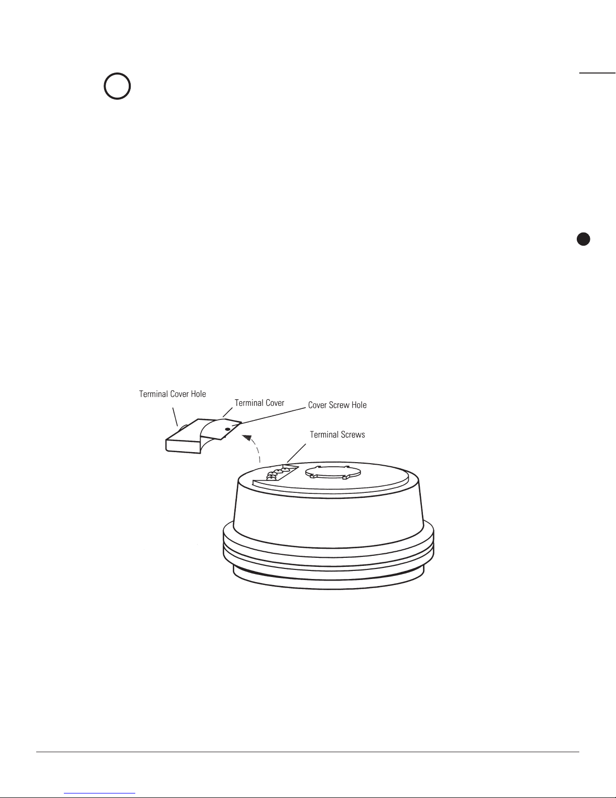
1Locate the terminal cover and remove the cover screw.
2Lift the terminal cover from the transmitter.
Refer to Figure 2.1.
3 Insert the end of the multi-conductor cable through the hole in the terminal cover
as shown in Figure 2.2.
Move the cover far enough down the cable to allow you to work with the end that
you just inserted.
Figure 2.1 Elements of the Transmitter
i
CHAPTER 2INSTALLING THE TRANSMITTER

TRICON/E/E2/E3 TRANSMITTER INSTALLATION AND MAINTENANCE GUIDE 2-3
Figure 2.2 Inserting Multi-Conductor Cable
Figure 2.3 Creating a Hook in the Wire
Figure 2.4 Connecting the Conductors to the Terminal Screws
4Strip the outer covering of the cable back approximately 11⁄2” from the inserted end.
5Separate the individual conductors and strip the insulation back approximately 1⁄2” from the end
of each conductor.
6Using the rounded shaft of the screwdriver, form a hook in the end of each bare copper wire.
(See Figure 2.3.)
7Loosen the terminal screws, as shown in Figure 2.4.
8 Position the wire hook of each conductor under the proper terminal screw according to the
appropriate wiring diagram.
Refer to Figure 2.5 and Table 2.1 for the wiring diagram.
Figure 2.2 Inserting Multi-Conductor Cable
Figure 2.3 Creating a Hook in the Wire
Figure 2.4 Connecting the Conductors to the Terminal Screws
Figure 2.2 Inserting Multi-Conductor Cable
Figure 2.3 Creating a Hook in the Wire
Figure 2.4 Connecting the Conductors to the Terminal Screws
CHAPTER 2INSTALLING THE TRANSMITTER

TRICON/E/E2/E3 TRANSMITTER INSTALLATION AND MAINTENANCE GUIDE 2-4
Figure 2.5 TRICON/E/E2/E3 Wiring
1The (+) indicates conventional current exiting the TRICON.
2This connection is a contact closure to ground and requires DC power to be supplied through a pull-up
resistor. Typical pull-up resistor values are 2K per 5 volts of the DC voltage.
9Place each wire hook so that it runs in a clockwise direction around the screw terminal,
with no insulation under the screw head.
10 Use the tip of the screwdriver to close the hooks around the terminal screws and
tighten the screws until snug.
Take care not to overtighten the terminal screws when completing the wiring.
Table 2.1 TRICON E/E2/E3 Wiring Codes
PIN #
TRICON/E
DIGITAL PULSE
(PRIOR TO 1/96)
TRICON/E2 & E3
MODEL DIGITAL PULSE MODEL
(AFTER 1/96)
TRICON/E, E2
& TRICON/E3
4-20MA MODELS
1 No Connection High Resolution Output 4-20mA Source (+)1
2 No Connection Count Direction24-20mA Return (-)
3 12-24VDC Power In (+) 12-24VDC Power In 24VDC Power In (+)
4 Common Ground (- side) Common Ground (- side) Common Ground (- side)
5 Pulse Output Pulse Output Pulse Output
i
CHAPTER 2INSTALLING THE TRANSMITTER

TRICON/E/E2/E3 TRANSMITTER INSTALLATION AND MAINTENANCE GUIDE 2-5
Testing the Wires
After wiring the transmitter, double-check to ensure it is wired correctly. Apply power to the TRICON
transmitter and check the output signals as follows:
nAt No Flow – there should be no pulses out of the digital output terminal, and a 4mA direct current
should be present in the 4-20mA loop.
nAt 1/2 Flow – the pulse rate out of the digital output terminal should be 1⁄2the maximum pulse rate, and
a 12mA direct current should be present in the 4-20mA loop.
nAt Maximum Flow – the pulse rate out of the digital output terminal should be equal to the maximum
pulse rate, and a 20mA direct current should be present in the 4-20mA loop.
Final Assembly
Once testing is complete, the transmitter is ready for the final steps of the assembly process.
1Shut off all power to the TRICON.
2Place a generous amount of Dow Corning #4 on all exposed wire and terminals.
3Fill the inside of the terminal cover with the moisture compound.
4Slide the terminal cover in place over the terminal screws.
5Fasten the terminal cover with the cover screw and tighten until snug.
Take care not to overtighten the cover screw when securing the terminal cover.
6Snap the strain relief fitting over the cable and push it into place in the cable entry hole.
7Wipe away any excess compound.
Mounting the Transmitter
Once the transmitter has been assembled, it is ready to be mounted. If you are installing a TRICON
transmitter on a meter that does not already have a register mounted on it, skip to step 4. If the meter does
have a register mounted, begin at step 1.
1Position the small end of the punch on the center of the seal pin at the base of the register.
2Using the hammer, drive the punch through the center of the seal pin. The head of the pin
should shear off.
i
CHAPTER 2INSTALLING THE TRANSMITTER
TRICON/E/E2/E3 TRANSMITTER INSTALLATION AND MAINTENANCE GUIDE 2-6
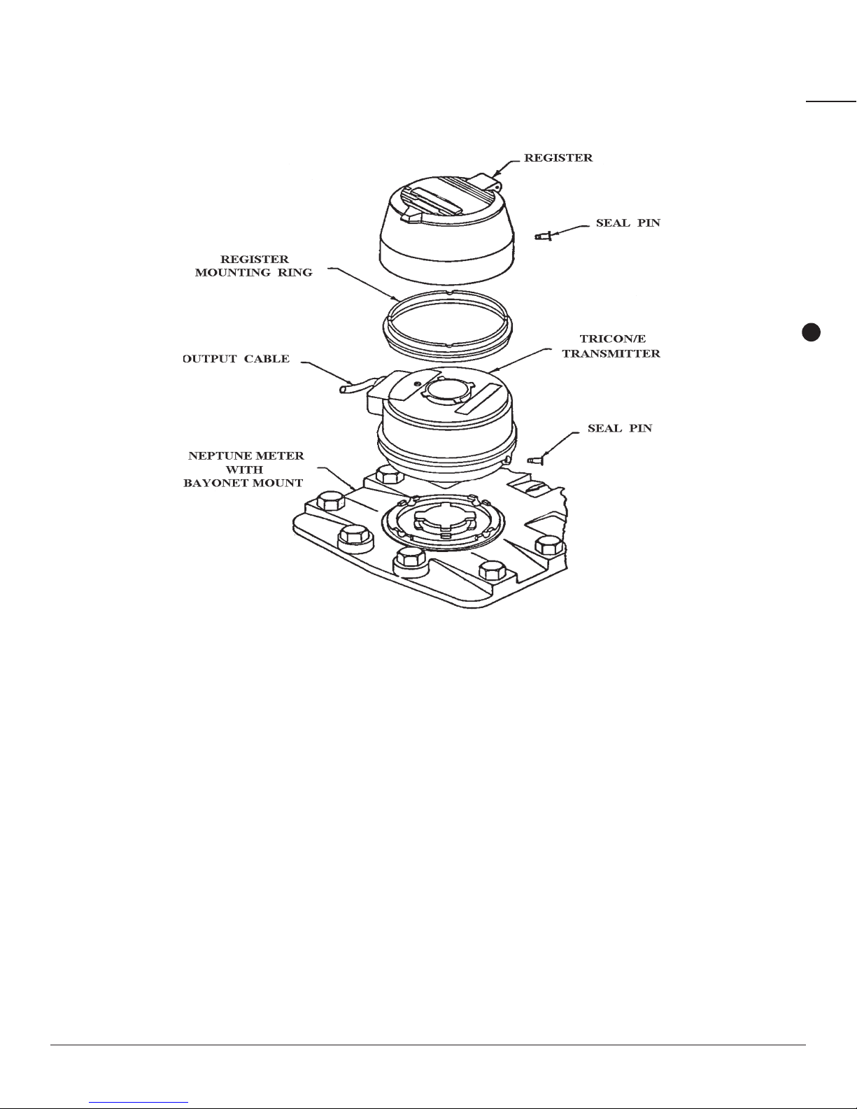
3Twist the register approximately 1⁄4turn counter-clockwise and remove it from the meter.
4Position the TRICON transmitter on the meter and twist it clockwise until it locks into place.
5Place the register mounting ring on top of the TRICON transmitter with the four rounded
grooves facing upward.
6Align the notch in the base of the register mounting ring with the terminal cover of the TRICON
and snap the ring into place.
When properly oriented, the register mounting ring should sit flush on top of the
TRICON transmitter.
7Position the register on top of the TRICON transmitter and register mounting ring, and twist it
clockwise until it locks into place.
8Drive the new seal pins into the register base and TRICON base to secure the installation
and prevent tampering.
Figure 2.6 Mounting the TRICON Transmitter
Refer to Figure 2.6 for assistance with the following steps.
CHAPTER 2INSTALLING THE TRANSMITTER

TRICON/E/E2/E3 TRANSMITTER INSTALLATION AND MAINTENANCE GUIDE 3-1
CHAPTER 3SPECIFICATIONS AND PERFORMANCE DATA
CHAPTER 3SPECIFICATIONS AND PERFORMANCE DATA
This chapter will provide you with the electrical specifications and the performance data
for the models of the TRICON transmitter.
ENVIRONMENTAL CONDITIONS
Operating Temperature 32° to 158°F (0° to 70°C)
Storage Temperature -40° to 185°F (-40° to 85°C)
Operating Humidity 0 to 95% RH, non-condensing
ELECTRICAL SPECIFICATIONS (TRICON/E3 MODELS)
Table 3.1 Pulse Outputs (over 0-70°C operating temperature)
PARAMETER DESCRIPTION MINIMUM TYPICAL MAXIMUM UNITS
Vol Low Digital Pulse Output Voltage — 0.4 — V
Voh High Digital Pulse Output Voltage 8.5 Vdcin–1.0V 12 V
Iol Current @ Vol — -10 — mA
Ioh Current @ Voh — +10 — mA
trl-h1Output Rise Time — — 2 uS
tfh-l1Output Fall Time — — 2 uS
1Measured with Rl=2.4KΩand Cl=50pF.
Table 3.2 4-20mA Model (over 0-50°C operating temperature )
PARAMETER DESCRIPTION MINIMUM TYPICAL MAXIMUM UNITS
Vcc Power Supply Voltage 22.5 — 26.5 V
IS Power Supply Current 20 — 80 mA
RlLoop Resistance 0 — 600 Ω
Gain Scaling Accuracy — — 0.5 %FS
Zero Offset Accuracy — — 0.2 %FS
Vol Low Digital Pulse Output Voltage — 0.4 — V
Voh High Digital Pulse Output Voltage 8.5 — 12 V
Iol Current @ Vol — -10 — mA
Ioh Current @ Voh — 10 — mA
*trl-h1Output Rise Time — — 2 uS
*tfh-l Output Fall Time — — 2 uS
1Measured with Rl=2.4KΩand Cl=50pF

TRICON/E/E2/E3 TRANSMITTER INSTALLATION AND MAINTENANCE GUIDE 3-2
Table 3.3 HF and UP/DN Models (over 0-70°C operating temperature )
PARAMETER DESCRIPTION MINIMUM TYPICAL MAXIMUM UNITS
Vcc Power Supply Voltage 11.5 — 26.5 V
IS Power Supply Current 20 — 50 mA
Vol Low Digital Pulse Output Voltage 0 — — V
Voh High Digital Pulse Output Voltage — 24 26.5 V
Iol Current @ Vol -1.0 — — A
Ioh Current @ Voh — 0.04 +1.0 W/Voh A
trl-h1Output Rise Time — — 2 uS
tfh-l Output Fall Time — — 2 uS
1Measured with Rl=2.4KΩand Cl=50pF.
Table 3.4 All Models Absolute Limits1
PARAMETER DESCRIPTION MINIMUM MAXIMUM UNITS
T (op) Operating Temperature 0 85 °C
T (stg) Storage Temperature -40 85 °C
Vcc Power Supply Voltage -30 30 V
RlOutput Load (pulse output) 1200 — KΩ
Iout Output Current (pulse output) — 10 mA
1These limits cannot be exceeded without possible damage.
PERFORMANCE DATA
Table 3.5 T-10 Disc Meters
METER
SIZE (in)
MAXIMUM FLOW
RATE (gpm)
MAXIMUM
CONTINUOUS
FLOW RATE (gpm)
MINIMUM FLOW
RATE (gpm)
NUMBER OF
PULSES PER
GALLON1
PULSE OUTPUT
@ MAXIMUM
FLOW RATE (Hz)1
FLOW RANGE
OF 4-20MA
OUTPUT (gpm)
5⁄820 10 1⁄4578.10 192.70 0–20
3⁄430 15 1⁄2322.60 161.30 0–30
1 50 25 3⁄4150.80 125.67 0–50
11⁄2100 50 11⁄267.57 112.62 0–100
2 160 80 2 37.30 100.00 0–160
1For the High Resolution Output of TRICON/E2 transmitters, multiply these values by 36, and for the TRICON/E3, multiply by 40.
CHAPTER 3SPECIFICATIONS AND PERFORMANCE DATA

TRICON/E/E2/E3 TRANSMITTER INSTALLATION AND MAINTENANCE GUIDE 3-3
Table 3.6 T-8 Disc Meters
METER
SIZE (in)
MAXIMUM
FLOW RATE
(gpm)
MAXIMUM
CONTINUOUS
FLOW RATE (gpm)
MINIMUM FLOW
RATE (gpm)
NUMBER OF
PULSES PER
GALLON1
PULSE OUTPUT
@ MAXIMUM
FLOW RATE (Hz)1
FLOW RANGE
OF 4-20MA
OUTPUT (gpm)
5⁄820 10 1⁄4473.60 157.87 0–24.412
3⁄430 15 1⁄2329.14 164.57 0–29.40
1 50 25 3⁄4126.55 105.46 0–59.582
11⁄2100 50 11⁄247.86 79.77 0–141.182
2 160 80 2 25.60 68.27 0–234.372
1For the High Resolution Output of TRICON/E2 transmitters, multiply these values by 36, and for the TRICON/E3, multiply by 40.
2T-8 disc meters are no longer manufactured. Therefore, all TRICON/E transmitters manufactured for disc meters are the T-10 type. In most cases, the newer
T-10 meter chamber is smaller than its corresponding T-8 meter chamber, which results in the TRICON/E having a theoretical “Flow Rate at 20mA Output” that
is greater than the Maximum Flow Rate allowed for the meter. This means that the T-10 type TRICON/E running on a T-8 meter will never actually reach the 20mA
output level during normal operation. The calculated flow rate required to produce a 20mA output is provided as a reference for use in calibrating the 4-20mA
receiving instrument.
Table 3. 7 Trident®Turbine (TT) Meters
METER SIZE
(in)
MAXIMUM
CONTINUOUS
FLOW RATE (gpm)
MINIMUM
FLOW RATE
(gpm)
NUMBER OF
PULSES PER
GALLON1
PULSE OUTPUT
@ MAXIMUM
FLOW RATE (Hz)1
FLOW RANGE
OF 4-20MA
OUTPUT (gpm)
2 200 3 4.6080 15.36 0 – 200
3 450 5 2.8900 21.68 0 – 450
4 1,000 10 1.5900 26.50 0 – 1,000
6 2,000 20 0.4640 15.47 0 – 2,000
8 (through S/N 31918014) 3,500 35 0.2493 14.54 0 – 3,500
8 (from S/N 31918274) 3,500 35 0.2253 13.14 0 – 3,873
10 (through S/N 31919282) 5,500 50 0.1600 14.67 0 – 5,500
10 (from S/N 31919300) 5,500 50 0.1472 13.49 0 – 5,981
1For the High Resolution Output of the TRICON/E2 transmitters, multiply these values by 9and for the TRICON/E3, multiply these values by 10.
Table 3.8 High Performance Turbine (HPT) Meters
METER SIZE
(in)
MAXIMUM
CONTINUOUS
FLOW RATE (gpm)
MINIMUM
FLOW RATE (gpm)
NUMBER OF PULSES
PER GALLON1
PULSE OUTPUT @ MAXIMUM
FLOW RATE (Hz)1
FLOW RANGE OF
4-20MA
OUTPUT (gpm)
11⁄2160 4 6.09500 16.25 0 – 160
2 200 4 6.09500 20.32 0 – 200
3 450 5 11.20000 84.00 0 – 450
4 1,200 10 7.55600 151.10 0 – 1,200
6 2,500 20 0.72730 30.30 0 – 3,000
8 4,000 35 0.75560 50.37 0 – 4,000
10 6,500 50 0.75560 81.86 0 – 6,500
12 8,000 120 0.75560 100.75 0 – 8,000
16 13,500 200 0.07556 17.00 0 – 13,500
20 22,000 300 0.07556 27.71 0 – 22,000
1For the High Resolution Output of the TRICON/E2 transmitters, multiply these values by 9and for the TRICON/E3, multiply these values by 10.
CHAPTER 3SPECIFICATIONS AND PERFORMANCE DATA

TRICON/E/E2/E3 TRANSMITTER INSTALLATION AND MAINTENANCE GUIDE 3-4
Table 3.9 Compound Meters
Compound Meter1Size and Type Turbine Element Disc Element
3”TRU/FLO 3” TT 5⁄8” T-10
4”TRU/FLO 4” TT 3⁄4” T-10
6”TRU/FLO 6” TT 1” T-10
2” HP TRU/FLO 2” HPT 5⁄8” T-10
4” PROTECTUS III 4” TT 1” T-10
6” PROTECTUS III 6” TT 11⁄2” T-10
8” PROTECTUS III 8” TT 2” T-10
10” PROTECTUS III 10” TT 2” T-10
4” HP PROTECTUS III 21” T-10
6” HP PROTECTUS III 211⁄2” T-10
8” HP PROTECTUS III 22” T-10
10” HP PROTECTUS III 22” T-10
1For TRICON/E Performance Specifications of Compound Meters, refer to the specification information of each respective meter element.
2Refer to Table 3.10 for the performance specifications of the 4”, 6”, 8”, and 10” HP PROTECTUS III Turbine Elements.
Table 3.10 4”, 6”, 8”, and 10” HP PROTECTUS III Turbine Elements Performance Specifications2
METER SIZE
(in)
MAXIMUM CONTINUOUS
FLOW RATE (gpm)
NUMBER OF PULSES
PER GALLON1
PULSE OUTPUT
@ MAXIMUM FLOW RATE (Hz)1
FLOW RANGE OF 4-20MA
OUTPUT (gpm)
4 1,200 7.5560 151.2 0 – 1,200
6 2,500 0.7556 37.78 0 – 2,888
8 4,000 0.6095 40.63 0 – 4,959
10 6,500 0.5333 57.78 0 – 9,209
1For the High Resolution Output of the TRICON/E2 transmitters, multiply these values by 9and for the TRICON/E3, multiply these values by 10.
2Note: This table is based on mounting HPT TRICON/E3 on the same size HP PROTECTUS III Turbine Element.
CHAPTER 3SPECIFICATIONS AND PERFORMANCE DATA

TRICON/E/E2/E3 TRANSMITTER INSTALLATION AND MAINTENANCE GUIDE 4-1
CHAPTER 4MAINTENANCE
CHAPTER 4MAINTENANCE
If you find that your TRICON system is not operating as expected when installed, use the following
guidelines to try to determine the source of the problem.
TROUBLESHOOTING
If the TRICON appears to be operating, but electronic flow indication does not agree with
mechanical register indication, try the following:
nVerify that the TRICON and register match the meter size and type.
If not, replace the TRICON and/or the register with the appropriate type to match the meter.
nVerify that the register turns smoothly when installed on the TRICON.
If not, replace the register or have it repaired to correct problems with excessive torque.
nVerify that the TRICON is wired and powered properly.
If not, correct the wiring/power problem.
nVerify compatibility and proper calibration of equipment to which the TRICON is connected.

TRICON/E/E2/E3 TRANSMITTER INSTALLATION AND MAINTENANCE GUIDE I-1
Numerics
4-20mA.......................................1-1
model, selecting.....................1-1
operating power.....................1-1
operating temperature...........3-1
specifications .........................3-1
A
absolute limits
electrical specifications .........3-2
assembly
of transmitter .........................2-5
illustrated...........................2-3
C
codes
wiring .....................................2-4
compound meters.......................3-4
contacting
technical support ...................1-1
cover screw................................2-2
cover screw hole
illustrated...............................2-2
customer support .......................1-1
D
digital pulse................................1-1
operating power
E.........................................1-1
E2/E3 .................................1-1
styles
disc.....................................1-1
turbine................................1-1
E
E/E2/E3. See transmitter
electrical specifications .............3-1
4-20mA...................................3-1
absolute limits .......................3-2
HF models ..............................3-2
pulse outputs .........................3-1
UP/DN models .......................3-2
environmental conditions...........3-1
equipment ..................................2-1
H
HF models
operating temperature...........3-2
specifications .........................3-2
High Performance Turbine. See HPT meters
HPT meters
performance data...................3-3
humidity, operating ....................3-1
I
inspecting
transmitter .............................2-1
installation
equipment needed .................2-1
preliminary check...................2-1
safety .....................................2-1
wiring transmitter ..................2-2
M
maintenance...............................4-1
meters
compound...............................3-4
HPT.........................................3-3
Neptune .................................1-1
T-10 disc.................................3-2
T-8 disc...................................3-3
TT ...........................................3-3
models
4-20mA...................................1-1
digital pulse ...........................1-1
moisture compound....................2-5
mounting
transmitter .............................2-5
illustrated...........................2-6
N
Neptune meter...........................1-1
O
operating
conditions...............................3-1
humidity .................................3-1
temperature ...........................3-1
operating power
4-20mA...................................1-1
digital pulse
E2/E3..................................1-1
digital pulse
E.........................................1-1
operating temperature
4-20mA...................................3-1
HF models ..............................3-2
pulse outputs ........................ 3-1
UP/DN model .........................3-2
INDEX

TRICON/E/E2/E3 TRANSMITTER INSTALLATION AND MAINTENANCE GUIDE I-2
P
performance
HPT meters.............................3-3
T-8 disc meters.......................3-3
TT meters ...............................3-3
performance data
T-10 disc meters.....................3-2
pre-installation...........................2-1
pulse outputs
operating temperature...........3-1
specifications .........................3-1
R
register mounting ring................2-5
illustrated...............................2-6
S
safety..........................................2-1
seal pin.......................................2-5
illustrated...............................2-6
shipment
inspecting...............................2-1
specifications
4-20mA...................................3-1
absolute limits .......................3-2
environmental ........................3-1
HF models ..............................3-2
pulse outputs .........................3-1
UP/ND models .......................3-2
storage
temperature ...........................2-1
storage, temperature .................3-1
storing
transmitter .............................2-1
strain relief fitting ......................2-5
T
T-10 disc meters
performance data...................3-2
T-8 disc meters
performance data...................3-3
temperature
operating ...............................3-1
storage ...................................3-1
terminal cover ...........................2-2
illustrated ..............................2-2
terminal cover hole ....................2-2
illustrated ..............................2-2
terminal screws .........................2-3
illustrated ..............................2-3
temperature
storage ..................................2-1
tools ...........................................2-1
transmitter
assembly ...................................2-5
illustrated ..............................2-6
elements, illustrated .................2-6
inspecting ..................................2-1
maintenance ..............................4-1
mounting ...................................2-5
illustrated ..............................2-6
storage ......................................2-1
storage temperature .................2-1
styles
4-20mA ..................................1-1
digital pulse ..........................1-1
testing wiring ............................2-5
troubleshooting .........................4-1
wiring ........................................2-2
wiring codes ..............................2-4
wiring diagram ..........................2-4
TRICON/E/E2/E3. See transmitter
Trident turbine. See TT meters
troubleshooting .........................4-1
TT Meters
performance data ..................3-3
Turbine style ..............................1-1
U
UP/DN models
operating temperature ..........3-1
specifications ........................3-2
W
wiring
codes .....................................2-4
diagram .................................2-4
testing ....................................2-5
transmitter ............................2-2
INDEX

..................................................................................................................
..................................................................................................................
..................................................................................................................
..................................................................................................................
..................................................................................................................
..................................................................................................................
..................................................................................................................
..................................................................................................................
..................................................................................................................
..................................................................................................................
..................................................................................................................
..................................................................................................................
..................................................................................................................
..................................................................................................................
..................................................................................................................
..................................................................................................................
..................................................................................................................
..................................................................................................................
..................................................................................................................
NOTES
TRICON/E/E2/E3 TRANSMITTER INSTALLATION AND MAINTENANCE GUIDE I-3

Neptune Technology Group Inc.
1600 Alabama Highway 229
Tallassee, AL 36078
USA
Tel: (800) 633-8754
Fax: (334) 283-7293
Neptune Technology Group (Canada) Ltd.
7275 West Credit Avenue
Mississauga, Ontario
L5N 5M9
Canada
Tel: (905) 858-4211
Fax: (905) 858-0428
Neptune Technology Group Inc.
Ejército Nacional No. 418
Piso 12, Desp. 1201-1202
Col. Chapultepec Morales
Delegación Miguel Hidalgo
11570 México, Distrito Federal
Tel: (525) 55203 5294 / (525) 55203 5708
Fax: (525) 55203 6503
neptunetg.com
IM TRICON/E 07.14 © Copyright 2014, Neptune Technology Group Inc. Neptune is a registered trademark of Neptune Technology Group Inc.
Other manuals for TRICON E
2
This manual suits for next models
2
Table of contents
Other Neptune Transmitter manuals
R900i Product manual")


