Ness 100-284 Quick start guide

1
FEATURES
Supervised radio link to SecurityGuard
Onboard backup battery
Mains Fail supervision and warning
Low Battery / Battery Missing / Battery
Capacity tests and warning
Telephone Line supervision
Fast & easy installation
No special tools required
Compatible with SecurityGuard II & III
•
•
•
•
•
•
•
•
Installation Notes
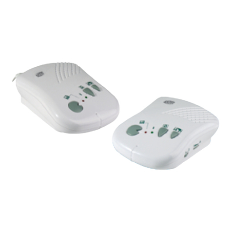
NESS RADIO DIALLER
Part No. 100-284
Hybrid Wireless/Landline dialler for Ness SecurityGuard systems

2
Introduction
The Ness Radio Dialler is a unique hybrid wireless/landline dialler which provides back-
to-base monitoring capability for Ness SecurityGuard products without the need for
additional telephone cabling.
The Ness Radio Dialler establishes a wireless link with a SecurityGuard and then sends
the alarm data via a telephone landline. The Ness SecurityGuard III (SGIII) has the
required radio interface built-in, whilst the SecurityGuard II (SGII) can easily be retro-
fitted with the optional radio interface.
The Ness Radio Dialler is designed to easily plug into an existing telephone wall socket
and does not need to be installed by a licensed telecommunications cabler.
The result is full back-to-base monitoring capability for the Ness SecurityGuard with
minimal installation and no extra cabling.

3
2m Radio
Dialler
Telephone Lead
2m Radio
Dialler
Telephone Lead
Mounting Point
Battery Compartment
Power In
Mounting PointMounting Point
Radio Dialler UnitRadio Dialler Unit
Existing
Telephone
Socket
Telephone Lead
Existing
Existing
Telephone
Socket
Telephone connection
The Ness Radio Dialler should be connects to an existing telephone wall socket,
preferably the first incoming telephone socket.
The existing telephone’s lead connects to the Radio Dialler’s LINE socket and the supplied
telephone cable is used to connect the Radio Dialler to the existing telephone.
FIG1. Connection Diagram Australia.
Radio Dialler Unit
Mounting Point
Power In
Battery Compartment
Wall Socket
FIG2. Connection Diagram New Zealand.

4
Programming & Setup (SGIII)
“OneShot” Programming downloads programming
data from the SGIII to the Radio Dialler and
ensures security by “locking in” the telephone
numbers 30 days after initial programming.
The installer is able to change the telephone
numbers as required only during the 30 day timer
period. All other programming options can be
changed at any time.
When the One-Shot timer has expired, the Radio
Dialler can only be re-programmed using the
Radio Dialler Upload/Download software, (See,
Remote Programming).
SGIII programming
The central station telephone numbers and client
account numbers are programming into the SGIII.
These numbers will be downloaded to the Radio
Interface at step 8 of the setup process.
1. Program the following extra options into the
SecurityGuard.
- Telephone Number (phone1)
- Telephone Number (phone2 optional)
- Client Account Number (client)
2. Once programming is completed leave the
SecurityGuard III in program mode.
Radio Dialler setup & connections
3. Mount the Radio Dialler securely to a wall with
screws or surface within reach of a mains outlet
and telephone socket.
NOTE: the preferred location for the Radio
Dialler is at the first incoming telephone socket
from the street. This will ensure that the dialler
has priority when it needs to send a message
to the central station.
4. Unplug the incoming line cable from the
existing telephone and plug it into the Radio
Dialler’s LINE socket. (See FIG1).
5. Connect the supplied telephone cable to the
Radio Dialler’s TELEPHONE socket and the
existing telephone’s LINE socket.
6a.Connect the AC adaptor lead into the power
socket on the rear of the Radio Dialler. Plug the
AC adaptor into a mains outlet and turn mains
power on.
6b.Connect the backup battery to the battery
socket inside the battery well.
7. On power-up, the indicator lights will briefly
flash out the software version number.
The MAINS ON light will be on and the RADIO
LINK light will double-flash. The Radio Dialler
is now in program mode and will remain so for
2 minutes or until it receives the ‘Learn’ signal
from the SecurityGuard.
Sending the SGIII ‘Learn’ signal
8. Before the Radio Dialler exits (4min) out of
program mode, press the ON button of one
of the SGIII radio keys.
The SGIII will exit program mode and
automatically upload the ‘Learn’ signal to
the Radio Dialler. (The Learn signal includes
the central station telephone numbers and
account number which were programmed at
Step 1).
Verifying Radio Dialler programming
9. The RADIO LINK light will turn on for about five
seconds to indicate that the Radio Dialler has
successfully downloaded the ‘Learn’ signal
from the SecurityGuard.
Once the download is completed, the Radio
Dialler will beep the signal strength (1-9) of the
‘Learn’ signal and the four front panel lights
will display the radio signal strength. The four
lights form a bar graph as follows:
SIGNAL STRENGTH
1-2 3-4 5-6 7-9
Mains On ON
Battery Low ON ON
Radio Link ON ON ON
Line Fault ON ON ON ON
The more LEDs on, the greater the signal
strength.

5
Front Panel Indicators
The front panel indicators (LEDs) are used to indicate the status of various Radio Dialler conditions.
ON: Mains is ok
FLASHING: Mains has been off for at least one
hour.
If mains failure persists for more than one hour,
a MAINS FAIL alarm is reported to the central
station. When the mains power is restored, a
MAINS FAIL restore is reported to the central
station (only if MAINS FAIL has been reported).
The dialler will beep five times every hour only if
there is a line or a dialler fault that will restrict the
alarm from being reported.
ON: If a backup battery is not connected the
dialler will continuously beep until a battery is
fitted. A LOW BATTERY alarm will be reported
to the central station only if the battery has been
missing for more than 60 seconds. This time delay
allows battery replacement without sending a low
battery report.
FLASHING, Single Flash: The backup battery
has discharged to below 25% capacity. The
battery should be replaced.
A LOW BATTERY alarm will be reported to the
central station. A LOW BATTERY RESTORE will
be reported when the battery has recharged to
approx.. 75% capacity.
FLASHING, Double Flash: The backup battery
cannot be charged or cannot hold a charge.
The battery should be replaced.
ON: Receiving a valid programming message
such as the Learn message from an SGIII.
FLASHING, Slowly: Dialler is not programmed.
FLASHING, Fast: In Program Mode indicates that
the dialler is already programmed.
OFF: Normal condition.
ON: Dialler is currently sending a message.
FLASHING, Single Flash: Telephone line failure.
The telephone has been disconnected. The Radio
Dialler tests the line every 30 seconds.
If during this time a Low Battery fault or Mains fault
occurs, the Radio Dialler will beep five times every
hour. This condition will clear with a successful
subsequent dialout.
FLASHING, Double Flash: Comms Failure. A
report to the central station has failed. If during this
time a Low Battery fault or Mains fault occurs, the
Radio Dialler will beep five times every hour. This
condition will clear with a successful subsequent
dialout.

6
Listen-in Mode
INSTALLER’S DIAGNOSTICS.
Apply a shorting link to J6 to enable Listen-in
mode.
All dialler activity will be heard via the onboard
piezo sounder.
Test Calls
SecurityGuard II: Test calls are sent weekly to the
central station. The time interval is fixed. The first
test call is sent 14 hours after leaving program
mode or after powering up the Radio Dialler.
SecurityGuard III: Test calls can be programmed in
intervals 1 day, 7days, 14 days, 30 days or OFF.
Remote Programming
The Radio Dialler can be programmed remotely
via PC and Ness Upload/Download software.
Remote programming can used either to:
a/ Reset the One Shot programming option
allowing the technician to reprogram the Radio
Dialler via the SecurityGuard.
b/ Or the phone1, phone2 and client numbers
can be remotely downloaded to the Radio Dialler.
Note, in this case, the numbers programmed in
the SecurityGuard may be different to the Radio
Dialler.
REMOTE PROGRAMMING
1. Ensure Radio Dialler is powered up.
2. Power up SGIII and press OFF to enter
PROGRAM mode. Radio Dialler will now be ready
to answer incoming calls for the next 5 minutes. If
the Dialler answers a call but does not verify within
30 seconds it will hang-up. Once a connection is
established, the Dialler will unconditionally hang-
up after 5 minutes if a hang-up is not requested
sooner by the remote end.
3. Once a connection is established, program
the SGIII/Radio Dialler system as required.
SGIII will exit PROGRAM mode when the Up/
down connection is terminated, or when the
SGIII PROGRAM mode timer expires, whichever
occurs first. If PHONE1 has been programmed,
then if data transfer to Radio Dialler has not been
successful within a short period, SGIII will raise
a system alarm indicating radio link failure with
the Dialler.
Dialling Method
The Radio Dialler auto-detects the dial tone and
dials in DTMF or Rotary as determined by the
dial tone.
In cases where the dial tone is undetectable or
non-standard (such a stutter-tone) the Radio
Dialler can be forced to dial in DTMF always.
Place a shorting link across pins 2 & 3 of the
J7 header on the main board to force DTMF
dialling.
Place a shorting link on
pins 2 & 3 of J7 to force
DTMF dialling.
SecurityGuard Supervision
The integrity of the radio link between the
SecurityGuard and the Radio Dialler is tested
by a supervision poll sent by the SecurityGuard
every 90 minutes.
If the radio dialler fails to receive eight consecutive
poll messages it will send a Radio Jamming alarm
to the central station (Contact ID 355-105).
A Restore message is sent when the Radio dialler
receives the next valid poll.
Place a shorting link on J6
to enable Listen-in Mode.
Radio PIR Supervision
Supervised Detector (380) sensor trouble
message including the device number is sent the
SGIII fails to see 24 consecutive polls from the
device. The restore will be sent when the device
a poll message or is next triggered.

7
Contact ID Reporting Codes
MESSAGE FORM
The Contact ID message is reported in the following format:
SSSS 18 Q XYZ GG CCC E
SSSS 4 digit Client Account number
18 Uniquely identifies this format as Contact ID
Q Event qualifier (1 = New alarm or Open; 3 = Restore or Close)
XYZ Event code (hexadecimal)
GG Group code. (always 00)
CCC Sensor/key ID + offset, or Type number (decimal)
E Error check
SGII SGIII
Report Name XYZ CCC XYZ CCC
Burglary by device 130 001-050 130 001-050
24hr by device 133 051-100 133 051-100
Siren box tamper 137 106 137 106
Sensor tamper by device 383 352-400 383 352-400
Panic by user 120 301-350 120 301-350
Duress by user 121 401-450 121 401-450
Medical Pendant 100 651-700 101 651-700
Radio Jamming 355 105 355 105
Radio Device Supervision Poll Fail (Detectors) 355 202-250 355 202-250
Radio Device Supervision Poll Fail
(Fixed Panic Button)
355 501-600 355 501-600
Dialler Radio Supervision Poll Fail 355 103 355 103
Dialler Mains Fail 301 102 301 102
SGIII Battery Test Fail - - 309 108
SGIII Low Battery - - 302 107
Radio Dialler Low Battery 302 101 302 101
Radio Device Low Battery 384 002-050 384 002-050
Open\Close with user ID 401 001-050 401 001-050
Test call 602 104 602 104
Cancel of Alarm message 406 108 406 001-050

8
NESS RADIO DIALLER
INSTALLATION NOTES
This revision April 2008
Document Part Number 890-217
For Ness Radio Dialler 100-284
COPYRIGHT NOTICE
All rights reserved. No part of this publication may be reproduced, transmitted or
stored in a retrieval system in any form or by any means, electronic, mechanical,
photocopying, recording, or otherwise, without the prior written permission of Ness.
Ness reserves the right to make changes to features and specifications at any
time without prior notification in the interest of ongoing product development and
improvement.
© 2008 Ness Security Products Pty Ltd ABN 28 069 984 372
Specifications
RX TYPE SAWR stabilised
BANDWIDTH (3dB) 800kHZ
OPERATING VOLTAGE 17V AC plug pack supplied
QUIESCENT CURRENT DRAW (SLEEP MODE) 1mA
RADIO FREQUENCY 303.85MHz
WEIGHT 450g
BACKUP BATTERY 8.4V 160mA NiMH
DIMENSIONS 210 x 140 x 35mm
Table of contents
Other Ness Intercom System manuals
Popular Intercom System manuals by other brands
HOLOVISION
HOLOVISION 400-A-VIK installation instructions

Contacta
Contacta STS-K020 Installation & user guide

Eyevision
Eyevision EV-D298F Series user manual
Aiphone
Aiphone JK-DA installation manual
urmet domus
urmet domus 1051 Installation, programming and functions manual
Aiphone
Aiphone MP-1S instructions


