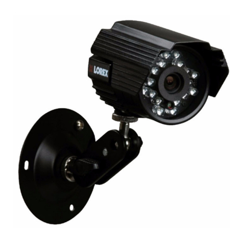
Ness 104-446 User guide

104-446 HD-SDI speed dome
www.nesscorporation.com
REV1.1
Installation & Setup Manual

User’s Manual
1
Table of Contents
1. Overview................................................................................................................................2
1.1 Features......................................................................................................................3
1.2 Package Contents .......................................................................................................4
1.3 Dimension ...................................................................................................................6
2. Camera Cabling.....................................................................................................................7
2.1 Product Application......................................................................................................7
2.2 Switch/Connector Definition.........................................................................................8
2.3 Communication Switch Setting ....................................................................................9
2.4 ID Setting...................................................................................................................10
2.5 Camera Control Protocol Setting ...............................................................................11
2.6 Power Connector.......................................................................................................12
2.7 Apply Alarm I/O .........................................................................................................12
2.8 RS-485 Connector Definition.....................................................................................12
3. Operation and Configuration..............................................................................................13
3.1 Display Format ..........................................................................................................13
3.2 Setup ID Display........................................................................................................14
3.3 Setup Title Display.....................................................................................................14
3.4 Setup Title Name.......................................................................................................14
3.5 Setup Time................................................................................................................15
3.6 Setup Schedule.........................................................................................................16
Appendix A: Technical Specification ........................................................................................17
Appendix B: Switch Settings Index Table.................................................................................19
Camera ID Setup..................................................................................................................19
Protocol Setup ......................................................................................................................26

User’s Manual
2
1. Overview
The Dome Camera delivers up to 432x zoom ratio (A3 Model) to capture clear
image in the distance. Continuous Auto Focus, Back Light Compensation, Auto
Exposure and Digital Slow Shutter functions are provided for clear and high
quality image. Removable IR cut filter ensures 24 hours operation, while Privacy
Masks are specially designed to avoid any intrusive monitoring at specific region;
all of the salient functions can be incorporated to meet your needs. The Home
function allows users to specify a preset position as the <home position> or
<home functions> (Sequence/Auto-pan/Cruise). Under the mode, Dome
Cameras can come back to the preset home position or functions when the
camera has been idle for a user-defined period of time. Additionally, the unique
Schedule function enables users to program a preset point or function
(Sequence/Auto-pan/Cruise) so that these actions can be automatically
performed in certain period of time.
The Dome Camera provides variable pan/tilt speeds ranging from a fast patrol
of 400° per second to a slow ramble of 5° per second with 0.225° pan/tilt
accuracy for fast and accurate tracking ability. The 360° endless rotation and
-10°~190° tilt travel make tracking the object passing directly beneath the dome.
Maximum 256 preset points can be programmed for precise location of target
areas, and users can also define Sequence lines, Auto-Pan lines and Cruise
routes for the camera to operate automatically. In addition, RS-485
communication port is available for remote control purposes.
The Integrated High Speed Dome Camera provides 4 alarm inputs and 2 alarm
relay outputs, and the smart alarm management mechanism can be
programmed through the OSD setup menu; certain function
(Preset/Sequence/Auto-Pan/ Cruise) can be activated when an alarm is
triggered.
Large set of built-in protocols provide connectivity to other surveillance systems.
The built-in protocols include DSCP, Pelco, VCL, Philips, AD-422, etc, which
allow the Dome Camera series to be integrated with other suppliers'
surveillance systems.

User’s Manual
3
1.1 Features
Precise and Accurate Performance
Auto Calibration
Preset accuracy of 0.225°
Preset speed up to 400°/sec.
Proportional Pan & Tilt Speed
Preset Position/ Sequence/ Auto-Pan/ Cruise
Dynamic Applications
Multi-language OSD
Schedule function
Multiple built-in Protocols
Up to 20 masking zones
4 alarm inputs, 2 alarm output
Motion Detection
Flexible mountings
Compact lightweight design for easy installation
All-in-one type
Superior Camera Image Quality
Minimum illumination 0.01 Lux (B/W)
Digital Slow Shutter
Electronic Shutter
Wide Dynamic Range
Auto White Balance
Backlight Compensation
Auto Exposure
Image Inverse
Removable IR Cut Filter
Digital Noise Reduction
Electronic Image Stabilizer

User’s Manual
4
1.2 Package Contents
Please check the box contains the items listed here. If any item is missing or
has defects, DO NOT install or operate the product and contact your dealer for
assistance.
Indoor Dome Camera Package
Camera Body
Optical Cover
Hard Ceiling Mount
M4 Screw (x4)
Plastic Anchors (x4)
Quick Guide
CD: Operation Manuals

User’s Manual
5
Outdoor Dome Camera Package
Dome Camera with
Outdoor Mount Kit
M3 Standard Screw (x1)
M3 Security Screw (x1)*
M5 Standard Screw (x1)
M5 Security Screw (x1)*
Waterproof Rubber
Quick Guide
CD: Operation Manuals
Optical Cover
Lubricant
Security Torx*
*Optional: For Vandal Proof Cover only.

User’s Manual
6
1.3 Dimension
Indoor
Outdoor

User’s Manual
7
2. Camera Cabling
Please follow the instructions below to complete SDI High Speed Dome Camera
cable connections.
2.1 Product Application
Connect the Dome Camera to other devices as shown in the diagram to
complete a video surveillance solution.
NOTE: To extend the network distance up to 1.2 km (4000 feet) and to
protect the connected devices, it is highly recommended to place a
repeater at the mid-point. However, a repeater may be needed in the
network distance less than 1.2 km if the used cables are not the CAT 5,
24-gauge cables; refer to 2.7 RS-485 Connector Definition.Refer to the
repeater’s manual for detailed information.

User’s Manual
8
2.2 Switch/Connector Definition
Configuring the Dome Camera’s ID and communication protocol are required
before connecting the Dome Camera to other devices. The switches used for
configuring these settings are located on the camera’s back plate. Additionally,
the 22-Pin Connector for Data Cable connection and ISP Connector for
firmware upgrade kit connection are also set on the back plate.
Please refer to the diagram and table accompanied with for use of each
switch/connector.
Indoor Outdoor
Item
Definition
Remark
A
I/O
ALARM I/O
B
ID
Dome Camera ID Setup DIP Switch
C
BNC
BNC Video Output
D
SETTING
Communication Switch Setting
E
Protocol
Camera Control Protocol Setting
F
RS485
RS485 Connector
G
AC24V Connector
Power connector

User’s Manual
9
2.3 Communication Switch Setting
The Camera’s communication switches are specified in the table below.
Communication Switch
SW 1
RS-485 Setting
SW 2
SW 3
SW 4
SW 5
Reserved
SW 6
Reserved
RS-485 is the interface that communicates the Camera and its control device;
for this reason, the RS-485 setup of the Camera and the control device must be
the same. The RS-485 default setting is half-duplex (see the diagram follows).
Please do not change the default setting without qualified specialist or supplier’s
notice.
RS-485 Setting
Half-duplex
Full-duplex
Video Output
RS-485 Connector

User’s Manual
10
2.4 ID Setting
Please assign an ID number to a Camera if there is more than one Camera in
the same network. The camera’s ID can be setup using the 10-bit ID Dip Switch,
which is located on the Camera’s back plate. If the Camera’s ID number is 6, for
instance, the ID switch SW 2 and SW 3 should be set to “ON”and the rest
should be set to “OFF”as shown below. Dip Switch configuration for ID No.
0~10 are listed in the table below. To complete ID setups, please refer to the
User Manual.
For switch configuration details, please refer to Appendix B: Switch Settings
Index Table.
NOTE: No two Cameras should be given the same ID, or
communication conflict may occur.

User’s Manual
11
2.5 Camera Control Protocol Setting
Define the protocol you are going to use basing on the devices of your
surveillance system. Generally, use one protocol even the devices are provided
from different manufacturers. Please refer to the table below for all supported
protocols with their matching switch numbers and baud rate and choose a
protocol for your Camera.
The table below shows various protocols with their matching switch numbers
and baud rate.
Switch No.
Protocol
Baud Rate
00
VCL
9600
01
Pelco D
2400
02
Pelco P
4800
04
Chiper
9600
05
Philips
9600
07
DSCP
9600
08
AD422
4800
09
DM P
9600
11
Pelco D
4800
12
Pelco D
9600
13
Pelco P
2400
14
Pelco P
9600
15
JVC
9600
21
Kalatel-485
9600
22
Kalatel-422
4800
Use the 6-bit dip switch (Camera Control Protocol Switch) to set your camera’s
control protocol and its baud rate. If select protocol “Pelco D”, which is of switch
no. 01 and baud rate 2400, for instance, set the SW-1 to “ON,”with the rest to
“OFF”as shown below.
For switch configuration details, please refer to Appendix B: Switch Settings
Index Table.

User’s Manual
12
2.6 Power Connector
Please refer to the illustrations below for power connector definition before
wiring.
SW 1
AC24V_1
SW 2
GND
SW 3
AC24V_2
2.7 Apply Alarm I/O
The Camera supports 4 digital alarm inputs and 2 digital alarm outputs. Please
make sure the alarm connections are properly wired before starting to configure
alarm related settings. Please refer to the pin definition table below for alarm
system wiring.
Pin
Definition
Pin
Definition
1
ALM_IN_1
7
ALM_OUT_NC_2
2
ALM_IN_2
8
ALM_OUT_NO_2
3
ALM_IN_3
9
GND
4
ALM_IN_4
10
ALM_OUT_COM_1
5
GND
11
ALM_OUT_NC_1
6
ALM_OUT_COM_2
12
ALM_OUT_NO_1
2.8 RS-485 Connector Definition
Please refer to the illustrations below for RS485 connector definition before
wiring.
RS485 Connector
SW 1
R-
SW 2
GND
SW 3
R+
SW 4
T-
SW 5
T+

User’s Manual
13
3. Operation and Configuration
3.1 Display Format
The information shown on the screen is described in terms of OSD display,
position and function description in the table below.
No.
Function
OSD Display
Description
1
Motion
MOTION
Alarm Detect Message
2
Alarm
ALARM 1
Alarm Message
3
Focus Modes
&
Backlight
A
Auto Focus Mode
M
Manual Focus Mode
X
Back Light Compensation OFF
B
Back Light Compensation ON
4
Booting
Message
XX…(Dome Type); ID: 001 (Default)
DSCP/9600 (Default)
INITIALIZING
Shows Dome Type, ID Address,
Protocol and Baud Rate
5
Error
Message
PAN ERROR
TILT ERROE
CAM MODULE ERROR
Shows system initializing error
message
6
Zoom
Ratio
x1
Present Zoom Ratio
(Optical Zoom/Digital Zoom)
7
Title
Maximum 20 characters for each title.
16 sets of title are available.
8
Camera ID
001
Show the camera ID
9
Time
XXXX/XX/XX XX:XX
Year/Month/Day Hour: Minute
10
Position
Display
XX YYY/YY
XX: facing direction of PTZ
including N, E, Z, W, NE, SE,
SW, SN
YYY/YY: angle of PZT, 0~359/
10~-90

User’s Manual
14
3.2 Setup ID Display
Press the direction key down to turn the MAIN MENU page from 1 to 2, and then
the menu item <ID DISPLAY> will be shown on the top. Users are allowed to
choose whether the Camera’s ID will be displayed on screen for identifying the
domes. Display the ID address of the selected Camera on the right bottom of
the screen by turning it <ON>. To hide the ID address of the selected dome, set
the item <OFF>.
3.3 Setup Title Display
Users are allowed to name a view area, where the title will be displayed on
screen for easy recognition.
Select <ON> to display the title set for a view area on screen while the camera
shooting the view area.
When <TITLE DISPLAY> is set <OFF>, no title will be displayed on screen even
titles have been set in advance.
3.4 Setup Title Name
Up to 16 zone titles can be set with maximum 20 characters for each title.
Follow the steps to set a camera title.
STEP 1: Operate the Camera to a view area where you want to set a title for
it.
STEP 2: Turn on the OSD and go to the <MAIN PAGE 2> to select <TITLE
SETTING>.
STEP 3: Select a number to represent the view area.

User’s Manual
15
STEP 4: Press the <CAMERA MENU> key (ENTER) on the keyboard to go
into the editing page.
TITLE SETTING: 01
0
1
2
3
4
5
6
7
8
9
EXIT
A
B
C
D
E
F
G
H
I
J
SAVE
K
L
M
N
O
P
Q
R
S
T
DELETE
U
V
W
X
Y
Z
:
/
.
,
TITLE:
ABC
STEP 5: Choose a character with direction keys and then press the
<CAMERA MENU> key (ENTER) to input. For example: <A>
<CAMERA MENU>, <B> <CAMERA MENU>, <C> <CAMERA
MENU>
TITLE: ABC
STEP 6: To delete input characters, move the cursor to <DELETE> and press
<CAMERA MENU> to delete the selected character.
STEP 7: When the setting is completed, move the cursor to <SAVE> and
press <CAMERA MENU> to save.
3.5 Setup Time
The time setting function is used to set the TIME related parameters of the
integrated high speed dome. Each item in the menu is listed as follows.
TIME DISPLAY
Select <ON> to display time information on the screen or <OFF> not to
display.
YEAR / MONTH / DAY
The items are for setting up the system date.
HOUR / MINUTE
The items are for setting up the system time.

User’s Manual
16
3.6 Setup Schedule
The schedule function enables users to program a preset point or function
(Sequence/Auto-pan/Cruise) automatically to perform in a specific period of
time.
SWITCH
Select <ON> to enable or <OFF> to disable the schedule function.
POINT
Users are allowed to arrange 32 sets of schedule point, i.e. each set of
schedule point can be assigned one kind of schedule modes.
HOUR / MINUTE
The items are for setting up the time to execute each schedule point.
MODE
This is for setting the schedule function of the selected schedule point;
the options are including None, Preset, Sequence, Autopan, Cruise, IR
Function, please refer to SDI High Speed Dome Camera OSD Menu for
more details about the setup steps of each mode,.
SCHEDULE RESET
Users can reset the whole schedule with the item.

User’s Manual
17
Appendix A: Technical Specification
A2 Model
A3 Model
Camera
Image Sensor
1/4” Sony CCD
Optical Zoom
26x
36x
Digital Zoom
1 ~ 12x variable
Effective Pixels
NTSC: 480k
PAL: 570k
Horizontal Resolution
650 TVL
Scanning System
NTSC / PAL
Synchronization
Internal / Line Lock
Video Output
1.0 Vp-p / 75 Ω, BNC
S/N Ratio
> 50 dB (AGC Off)
Minimum Illumination
0.1 lux; 0.01lux (B/W)
Focal Length
3.4 ~ 88.4 mm
3.4 ~ 122.4 mm
Focus Mode
Auto / Manual
White Balance
Auto / Manual
Iris Control
Auto / Manual
Electronic Shutter
1/1 ~ 1/10k sec.
AGC Control
Auto / Manual
Backlight Compensation
On / Off
Lens
FOV
Wide: 57.8 ゚(H)
Tele: 2.35 ゚(H)
Wide: 57.8 ゚(H)
Tele: 1.7 ゚(H)
Operation
Pan Travel
360°endless
Tilt Travel
-10°~ 190°
Manual Speed
0.5°~ 90°/s
Presets
256
Preset Accuracy
0.225°
Preset Speed
5°~ 400°/s
Sequence
8
Auto Pan
4
Cruise
8
Privacy Mask
20
Proportional Pan & Tilt
On / Off (Pan and tilt speed proportional to zoom ratio)
Resume after Power loss
Yes
Home Function
Preset / Sequence / Auto pan / Cruise
Auto Flip
Image / Mechanical / Off
Digital Slow Shutter
On / Off
Motion Detection
On / Off
Wide Dynamic Range
On / Off
Day / Night: IR Cut Filter
On / Off
Image Freeze
On / Off
Image Inverse
On / Off
Noise Reduction
2D
On / Off
3D
On / Off
Electronic Image Stabalizer
On / Off
Multiple Languages
English / French / German / Italian / Japanese / Polish / Portuguese /
Russian / Spanish / Turkish / S. Chinese / T. Chinese
Built-in Protocol
DSCP / Pelco P / Pelco D / AD422 / Philips / Kalatel / VCL / JVC
Zone Title
16
Alarm
Input
4
5V 10kΩ pull up
Output
2
Relay output, max. 2A DC 30V / 0.5A AC 125V
Alarm Reaction
Preset / Sequence / Auto Pan / Cruise

User’s Manual
18
General
Environment
Indoor / Outdoor
Controller Interface
RS-485
Operating Temperature
Indoor
0°C ~ 40°C (32°F ~ 104°F)
Outdoor
-40°C ~ 50°C (-40°F ~ 122°F)
Dimension
Indoor
∅171.7 x 228.7 mm (∅6.7 x 9 in.)
Outdoor
∅191.9 x 382.1 mm (∅7.5 x 11.1 in.) w/ Sunshield
Weight
Indoor
1620 g (3.57 lb)
Outdoor
2320 g (5.11 lb)
Power Source
Indoor
AC 24V ± 10%
Outdoor
AC 24V ± 10%
Power Consumption
Indoor
20 W
Outdoor
65 W (w/ Heater)
Regulatory
CE / FCC / RoHS / IP66 (Outdoor)

User’s Manual
19
Appendix B: Switch Settings Index Table
Please refer to the switch settings below for Mini Speed Dome Camera’s ID and protocol
setup.
Camera ID Setup
ID No.
SWITCH SETTING
SW-1
SW-2
SW-3
SW-4
SW-5
SW-6
SW-7
SW-8
SW-9
SW-10
0
OFF
OFF
OFF
OFF
OFF
OFF
OFF
OFF
OFF
OFF
1
ON
OFF
OFF
OFF
OFF
OFF
OFF
OFF
OFF
OFF
2
OFF
ON
OFF
OFF
OFF
OFF
OFF
OFF
OFF
OFF
3
ON
ON
OFF
OFF
OFF
OFF
OFF
OFF
OFF
OFF
4
OFF
OFF
ON
OFF
OFF
OFF
OFF
OFF
OFF
OFF
5
ON
OFF
ON
OFF
OFF
OFF
OFF
OFF
OFF
OFF
6
OFF
ON
ON
OFF
OFF
OFF
OFF
OFF
OFF
OFF
7
ON
ON
ON
OFF
OFF
OFF
OFF
OFF
OFF
OFF
8
OFF
OFF
OFF
ON
OFF
OFF
OFF
OFF
OFF
OFF
9
ON
OFF
OFF
ON
OFF
OFF
OFF
OFF
OFF
OFF
10
OFF
ON
OFF
ON
OFF
OFF
OFF
OFF
OFF
OFF
11
ON
ON
OFF
ON
OFF
OFF
OFF
OFF
OFF
OFF
12
OFF
OFF
ON
ON
OFF
OFF
OFF
OFF
OFF
OFF
13
ON
OFF
ON
ON
OFF
OFF
OFF
OFF
OFF
OFF
14
OFF
ON
ON
ON
OFF
OFF
OFF
OFF
OFF
OFF
15
ON
ON
ON
ON
OFF
OFF
OFF
OFF
OFF
OFF
16
OFF
OFF
OFF
OFF
ON
OFF
OFF
OFF
OFF
OFF
17
ON
OFF
OFF
OFF
ON
OFF
OFF
OFF
OFF
OFF
18
OFF
ON
OFF
OFF
ON
OFF
OFF
OFF
OFF
OFF
19
ON
ON
OFF
OFF
ON
OFF
OFF
OFF
OFF
OFF
20
OFF
OFF
ON
OFF
ON
OFF
OFF
OFF
OFF
OFF
21
ON
OFF
ON
OFF
ON
OFF
OFF
OFF
OFF
OFF
22
OFF
ON
ON
OFF
ON
OFF
OFF
OFF
OFF
OFF
23
ON
ON
ON
OFF
ON
OFF
OFF
OFF
OFF
OFF
24
OFF
OFF
OFF
ON
ON
OFF
OFF
OFF
OFF
OFF
25
ON
OFF
OFF
ON
ON
OFF
OFF
OFF
OFF
OFF
26
OFF
ON
OFF
ON
ON
OFF
OFF
OFF
OFF
OFF
27
ON
ON
OFF
ON
ON
OFF
OFF
OFF
OFF
OFF
28
OFF
OFF
ON
ON
ON
OFF
OFF
OFF
OFF
OFF
29
ON
OFF
ON
ON
ON
OFF
OFF
OFF
OFF
OFF
30
OFF
ON
ON
ON
ON
OFF
OFF
OFF
OFF
OFF
This manual suits for next models
2
Table of contents
Other Ness Security Camera manuals
