nest 105005US User manual

Nutating Mixer
105005US/EU
User’s Manual
www.cell-nest.com

Section 1 Inspection and Installation
Section 2 Overview
Section 3 Operation
Section 4 Safety Tips and Maintenance
Section 5 Troubleshooting
Section 6 Warranty
Packing List
Connections
Structure Diagram
Specifications
Operation of the Control Panel
Settings
Environmental Conditions
Safety Instructions
Loads and Speed
1-1
1-1
1-2
1-2
2-1
2-1
2-1
2-2
2-3
6-1
5-1
4-1
3-1
3-1
3-1
Table of Contents
1. Inspect package and contents upon receipt of the instruments. If the package is
severely damaged or if there are any missing pieces, please contact the manufacturer
immediately.
2. Unpack the instrument, ensure all parts of the instrument and accessories are not
missing or damaged. Make sure to take out all the components before discarding
packing. If there are any missing or damaged pieces, please contact the manufacturer
immediately.
3. Place the instrument on a level and firm surface to avoid vibration and noise.
4. This is the general user manual for three instruments. Please make sure to refer to
the corresponding chapter for your instrument.
Section 1 Inspection and Installation
1 1-
1.1 Packing List
Table -1 Packing List
1
6
User Manual
105005US/EU
2
1
1
Ceneral Power Adaptor
Dimpled Rubber Mat
Figure
Model
Power Supply Cable
Rubber Strips
Product Name Nutating Mixer
Nutating Mixer
1050 05
User’s Manual

1 2-2-1
Section 1
Inspection and Installation
1.2 Connections
Power Cable
Machine
Power Adaptor
1.3 Structure Diagram
Foot(4)
Control Panel
House
Tray
Dimpled Rubber
Mat Note: Maximum speed/tilt angle may vary with heavy or unbalanced loads.
2.1 Specifications
Section 2 Overview
Speed Range
Display Mode
Display Accuracy
Speed Accuracy
Tilt Angle
Tilt Angle Accuracy
Rotation Angle
Maximum Load
(Centered on tray)
Timer Range
Requirement
Tray Dimensions
Package Dimensions
Net Weight
Gross Weight
Noise Level
Overall Dimensions
LED
1rpm
2 to 80rpm
±1rpm
0 to 360°
7°
±1°
0.8kg
0~99h59min
100~240V, 50Hz/60Hz, 0.8A
7.3kg(16.1lb)
9.4kg(20.7lb)
﹤55 dB with no load when ambient noise is 45 dB
307×267mm (12.1×10.6in.)
440×296×189mm (17.3×11.6×7.4in.)
505×385×270mm (19.9×15.2×10.6in.)
5 to 40 ℃(41 to 104 ℉)
0 to 60 ℃(36 to 124 ℉)
20% to 85%,
Application Environmental Conditions: indoor use
Temperature
Humidity
Altitude
Voltage Fluctuation ±10% of the nominal voltage
≤2,000 m
Storage Environmental Conditions
Temperature
Humidity 20% to 90%, non-condensing
2.2 Environmental Conditions

Section 2
Overview
WARNING DO NOT use the Nutating Mixer in a hazardous atmosphere or with
hazardous materials for which the unit was not designed. Also, the user should
be aware that the protection provided by the equipment may be impaired if
accessories used are not provided or recommended by the manufacturer, or are
used in a manner not specified by the manufacturer.
CAUTION ! To avoid electrical shock, completely cut off power to the unit by
disconnecting the power cord from the unit or unplug from the wall outlet.
Disconnect unit from the power supply prior to maintenance and service. Any
spills should be removed promptly. Biohazard spills should be cleaned using
approved liquid promptly. Solvent spills are a fire hazard. Stop the unit
immediately, and DO NOT operate until clean up is complete and vapors have
dissipated.
DO NOT immerse the unit for cleaning.
DO NOT operate the unit if it shows signs of electrical or mechanical damage.
Please read the entire instruction manual before operating the .Nutating Mixer
2.3 Safety Instructions
Place the loads in the recommended positions below:
1. Place load at the center of the tray
2. Place loads symmetrically around the center of the tray
3. Make sure to use rubber strips to fasten containers onto the tray
Position of Loads
Centered Placement
Section 2
Overview
2 2-2-3
Asymmetric loading or unloading may affect the normal operation of the instrument
and may even cause unpredictable damage.
Symmetrical placement
Asymmetrical placement
25
75
150
175
225
80
80
800
600
450
225
30/40
80
80
2.4 Loads and Speed
Cell Culture Flask
Specification(cm2) ≤Capacity(ml)Maximum Speed
(rpm)
Warning: The rotation speed is inversely proportional to the load. When the instrument is
in use, it is recommended to adjust the rotation speed from low to high, step by step and
run the machine at an appropriate speed to avoid accidental spillage of liquids.
For safety, please always using rubber strip to hold samples in place.
80

①
③④
⑤⑥
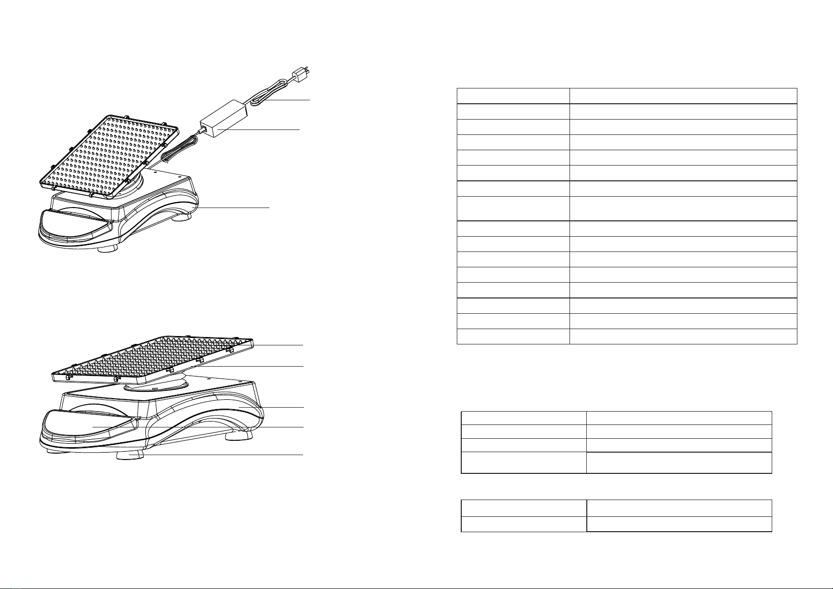
This Chapter covers introduction of the control panel and its operation.
1. Start/Stop button: Start or stop the instrument
2. RUN indicator light: The light is on when the instrument is running and off when the
instrument is in standby.
3. TIME display window: The window shows cumulative time (in continuous mode) or
remaining time (in timer mode). The range of time displayed is 0 to 99 hours and 59
minutes. The accuracy is 1 minute.
4. SPEED display window: The window shows set speed (when the instrument is in
standby) or current speed (when the instrument is running).
5. Set Time Buttons: UP/DOWN Arrow buttons are used to increase/ decrease the set
time of the instrument.
6. Set Speed Buttons: UP/DOWN Arrow buttons are used to increase/ decrease the set
speed of the instrument.
Section 3 Operation
3.1 Operations of the Control Panel
3.2 Settings
.
②
Section 3
Operation
3 1-3 2-
Speed Settings
Press the “ ” or “ ” arrow button below the SPEED display window. When the number
shown on the display window starts flashing, press “ ” or “ ” arrow button to increase
or decrease the speed value. Release the button when the speed shown on the display
window reaches the set value. The speed setting is finished after the number shown on the
display window has flashed twice.
Note: press the “ ” or “ ” arrow button for a longer time to accelerate the setting.
Run and Stop
1. Continuous Mode
Press “ ” button and the instrument will start running with the specified settings and the
RUN indicator light will be on. The TIME display window will show the cumulative time
and the SPEED display window will show the current speed. Press “ ” button again and
the instrument will slow down until it stops. The instrument will then be in standby and the
two display windows will show the set values.
2. Timer Mode
Press button the instrument will start running with the specified settings and the “ ”
RUN indicator light will be on. The TIME display window will show the remaining time and
the SPEED display window will show the current speed. Press button again and the“ ”
instrument will slow down until it stops. The instrument will then be in standby and the two
display windows will show the set values.
If the power supply is cut off suddenly while the instrument is in operation, the unit will
automatically run at the previously set parameter upon power restoration. The display
window will flash. Press any button to stop flashing.
Finish Operation
After the operation is finished, please press the power switch at the back right side the
instrument and put it into the “O” state. Unplug the instrument and store the instrument
according to the storage guide.
Alarm System
When the normal operation is obstructed or stopped by malfunctioning, the instrument
will stop running automatically within 2 minutes and the alarm will sound.
Power Recovery
1. Connect all the components according to the figures shown on page 1-2 of this
manual. Use grounded power outlet.
2. Press the power switch "I" side and switch on the instrument.

Section 4 Safety Tips and Maintenance
Safety Tips
1. Use independent power supply.
2. Check if the local power supply voltage is suitable for use.
3. Do not drag the power supply cable when unplugging.
4. Do not use non-specified power cable nor damage cable.
5. Service should only be performed by a qualified professional.
6. The power supply must be unplugged under the following situations:
a. when the unit is moved
b. when the electrical cabinet or the moving component is opened
c. when the equipment is malfunctioning
d. when the equipment is not in use
a. This instrument uses a high-accuracy motor. It is maintenance free and has a long
service time, high quality, and low noise level.
b. Surfaces can be cleaned with a mild detergent and water. Liquid is not allowed inside
the dust cover.
Maintenance
Warning: Avoid dripping detergent or water into the instrument during cleaning.
If accidental spillage of liquids caused by mishandling or contained breakage occurs on
the surface of the instrument, please shut down the instrument and clean up the liquid
immediately.
If the liquid has already spilled into the unit, cut off the power supply first and immediately
clean up the liquid at the surface of the instrument. Place the instrument in a ventilated
and dry environment for 24 hours before reuse. If the instrument is not functioning after
drying for 24 hours, please contact the manufacturer.
Warning: Disassembling/Assembling without a qualified professional's guidance may
cause malfunctioning of the instrument.
Clean Spill
4 1-5 1-
Section 5 Troubleshooting
Error
No shaking of the tray
Loud noise
Other
Cause
Power disconnected
Switch off
Power adaptor failure
Over-weighted or
unbalanced load
Electrical
malfunction
Mechanical
malfunction
Keep record for maintenance
Solution
Connect the power
Switch on
Replace power adaptor
Adjust the weight and position
of load, decrease rotation
speed
Contact NEST
Contact NEST
Cannot start machine,
LED display window
off
Load moving
Tray loose
House loose
Change Dimpled Rubber
Mat or fasten load
Fasten fixing screws on the
tray
Fasten fixing screws at the
House
Please refer to the following table to troubleshoot if any malfunction occurs. If the problem
still exists, contact your local sales representative.

6 1-
Customer Service Phone:
0510-68788698
Warranty Card
The certificate is an important basis for product warranty, please take good care of it!
Warranty certificate
Phone
E-mail
Product Model
The date of sale
User name
E-mail Address
Zip code
Product Name
Production Number
● Warranty
1 year warranty
The following circumstances,Warranty is not implemented:
1. Over the warranty period; (warranty period starts from the date of
purchase within one year)
2. Damage caused by use maintenance violate the instruction requirement
of use, maintenance, custody
3. Damage caused by Non-professionals dismantlement
4. No valid invoice; (except the goods can prove the validity of the warranty)
5. Product model and serial number of products does not match the
warranty certificate
6. The damage caused by force majeure;
Dear users, the above information is completed by the sellers and stamped effect.
Completed by maintenance organizations, and they should help customers to
paste maintenance records in the appropriate position!
Maintenance records
The
1
time
The
2
time
The
3
time
Maintenance company’s name
Address
Maintenance documents No.
Maintenance company’s name
Address
Maintenance documents No.
Maintenance company’s name
Address
Maintenance documents No.
Maintenance Date
Tel
Maintenance personnel to sign
Maintenance Date
Tel
Maintenance personnel to sign
Maintenance Date
Tel
Maintenance personnel to sign
This manual suits for next models
1
Table of contents