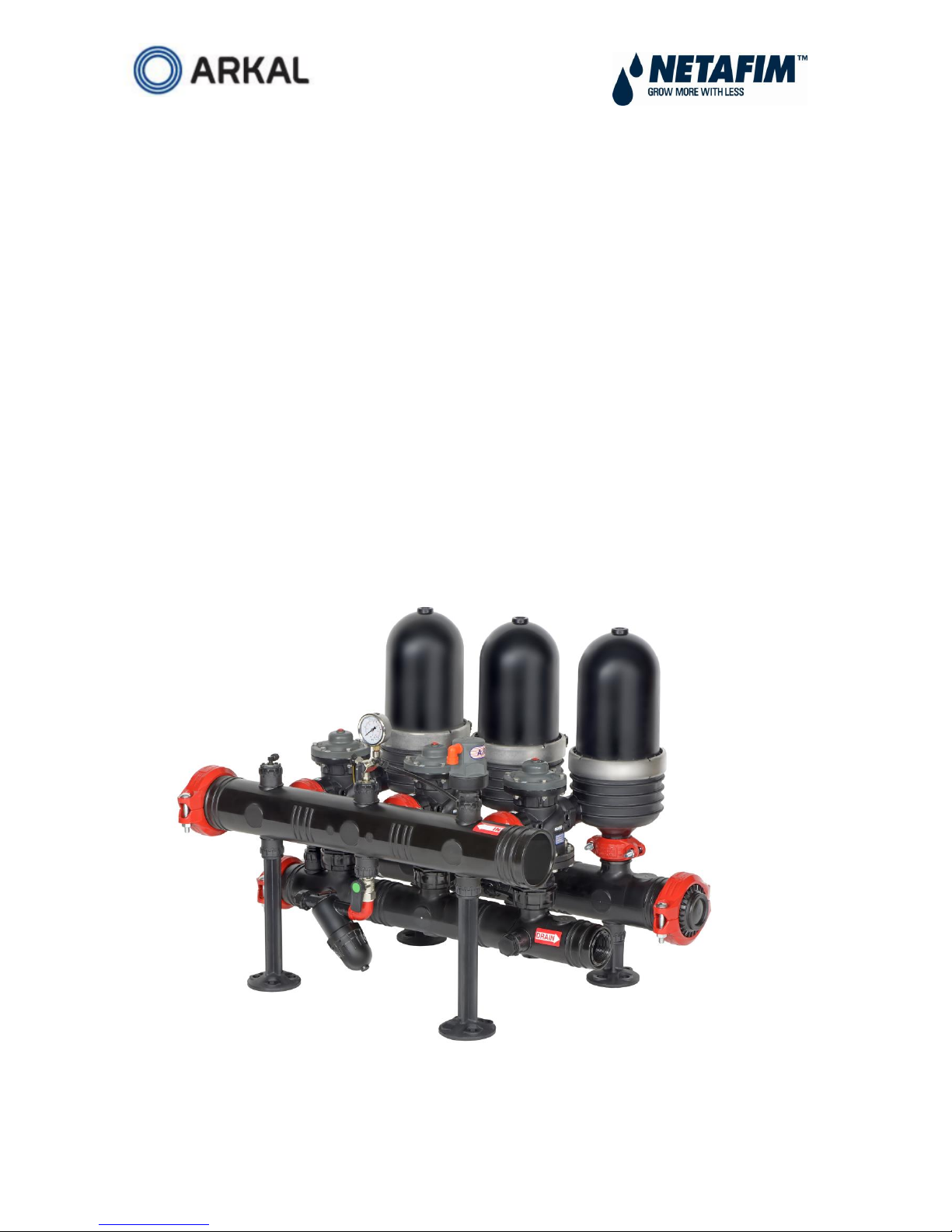
Netafim Arkal 3" Spin-Klin Battery User manual


Other manuals for Arkal 3" Spin-Klin Battery
1
Other Netafim Water Filtration System manuals

Netafim
Netafim SANDSTORM User manual

Netafim
Netafim Apollo Instruction Manual

Netafim
Netafim Arkal 3" Spin-Klin Battery Installation and operating instructions

Netafim
Netafim SANDSTORM User manual

Netafim
Netafim AlphaDisc Series User manual

Netafim
Netafim APOLLO DISC-KLEEN Instruction Manual

Netafim
Netafim SCREENGUARD User manual

Netafim
Netafim Arkal 2" Spin-Klin Compact Stand Alone... User manual

Netafim
Netafim SANDSTORM User manual

Netafim
Netafim SCREENGUARD User manual


Popular Water Filtration System manuals by other brands

Purwater
Purwater PW-RO4L Installation and operating instructions

Spear & Jackson
Spear & Jackson BoilerMag XC BMXC22 Installation & maintenance

3M
3M CFS101BWF Installation and operating instructions

Antunes
Antunes VZN-441 owner's manual

Pentair
Pentair INTELLICHLOR COMSYS-16 installation guide

Sicce
Sicce GREEN RESET 25 instructions


