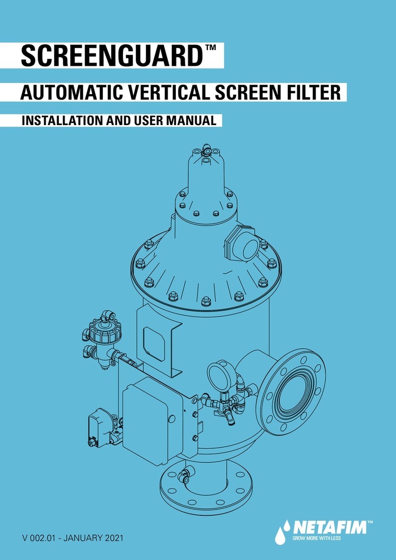
Netafim SCREENGUARD User manual

OPERATION, INSTALLATION & MAINTENANCE GUIDE
SCREENGUARD™ AUTOMATIC
SCREEN FILTERS
FILTRATION

2•SCREENGUARD AUTOMATIC SCREEN FILTERS OPERATION INSTALLATION AND MAINTENANCE GUIDE

SCREENGUARD AUTOMATIC SCREEN FILTERS OPERATION, INSTALLATION AND MAINTENANCE GUIDE •3
General Information.......................................................................................................4
Specifications.................................................................................................................4
Operations.......................................................................................................................6
Dimensions & Weight.................................................................................................... 7
Installation.......................................................................................................................8
Maintenance
Battery Removal & Replacement................................................................9
Control Card Removal & Replacement.....................................................10
Solenoid Removal & Replacement ...........................................................11
Hydraulic Piston Assembly & Replacement............................................12
Coarse Screen Removal & Replacement ................................................13
Fine Screen Assembly Removal & Replacement...................................14
Dirt Collector Removal & Replacement ...................................................15
Periodic Checks...........................................................................................16
Troubleshooting
Pressure Difference Between Inlet and Outlet ......................................17
Filter Flushing Cycle ....................................................................................17
Replacement Parts ......................................................................................................18
TABLE OF CONTENTS

4•SCREENGUARD AUTOMATIC SCREEN FILTERS OPERATION INSTALLATION AND MAINTENANCE GUIDE
• Prior to installation or handling of the filter, read carefully the installation and operation instructions carefully.
• Confirm filter draining prior to service.
• Take precautions while lifting, transporting or installing the filter.
• Installation of the filter should be performed so as to avoid direct water splashing on any of the filter parts and
especially on the electronic control unit.
• Confirm that filter weight, when full, meets the support construction requirements.
• Prior to installation confirm that line pressure matches filter’s operational pressure.
• During installation, use standard flanges and connections only.
• Check that all filter flange bolts are properly secured.
• Please note, the filter enters a flushing mode automatically, without prior warning.
• Use original parts only when servicing the filter.
• NETAFIM can not accept responsibility for any changes or modifications to the equipment.
SPECIFICATIONS
GENERAL INFORMATION
• Minimum operating pressure: 30 psi
• Maximum Operating Pressure: 150 psi
• Maximum Water Temperature: 149˚ F (65˚ C)
• End Connections: Flanged
• Screen Mesh Sizes: 080, 120, 150, 200
• Sizes: 4”, 6”, 8” and 10”
• Control voltage: DC Latching
• Filter housing: baked epoxy, carbon steel coated
HEADLOSS (FLOW VS. PRESSURE)
1,000 2,000 2,5001,500450
0.14
14
1.4
FLOW RATE (GPM)
PRESSURE (psi)
10"
8"
6"
4"

SCREENGUARD AUTOMATIC SCREEN FILTERS OPERATION, INSTALLATION AND MAINTENANCE GUIDE •5
SPECIFICATIONS
FIGURE 1
1 Inlet
2 Coarse Screen
3 Fine Screen
4 Flushing Valve
5 Hydraulic Piston
6 Flushing Chamber
7 Dirt Collector
8 Suction Nozzle
9 Hydraulic Motor
10 Outlet
11 Electronic DP Unit
12 Control Unit
13 Solenoid Valve
14 Adapter 2”
KEY DESCRIPTION
AUTOMATIC SCREEN FILTERS
MESH / MICRON
MESH
MICRON
80
200
120
120
150
100
200
80
SPECIFICATIONS
SIZE
4”
6”
8“
10”
1,300 SQ. IN.
1,300 SQ. IN.
1,300 SQ. IN.
1,815 SQ. IN.
SCREEN AREA
132 GPM
132 GPM
132 GPM
396 GPM
BACKFLUSH
FLOW RATE
440 GPM
700 GPM
1,320 GPM
2,000 GPM
MAXIMUM
FLOW RATE
The ScreenGuard self-cleaning filter enables high quality filtration from 80-200 mesh from various types of fluid
sources such as sewage, reservoirs, rivers, lakes, and wells.

6•SCREENGUARD AUTOMATIC SCREEN FILTERS OPERATION INSTALLATION AND MAINTENANCE GUIDE
OPERATIONS
FILTER OPERATIONS (FIGURE 1)
• Water enters the filter through the “Inlet” (1) and passes through the coarse screen (2) that functions as a “first stop”
for rough particles.
• Water then reaches the fine screen (3), which further purifies the flow by separating smaller particles from the water
As more water flows through, impurities build up on the fine screen. As impurities on the screen accumulate, a
pressure imbalance is built up between the internal section of the fine screen (3) and its external section.
• When the difference in pressure (DP) reaches the preset value in the electronic control unit (12), a series of events is
triggered while the water continues to flow to the user.
• The flushing valve (4) opens, pressure is released from the hydraulic piston (5) and water flows outside.
• Pressure in the hydraulic motor chamber (9) and the dirt collector (7) is significantly lowered, and the dirt collector
nozzles (8) begin a suction process.
• The water flows through the hydraulic motor (9) which rotates the dirt collector (7) around its axis.
• The pressure released from the piston (5) and the high pressure inside the filter cause linear movement of the dirt
collector. The combination of the linear movement and rotation significantly cleans the entire internal screen
(3) surface.
• The flushing cycle takes about 10 seconds. The flushing valve (4) closes at the end of the cycle and the increased
water pressure returns the hydraulic piston (5) to its initial position. The filter is now ready for the next flushing cycle,
with clean and filtered water flowing through the “Outlet” (10).
Note: At the back of the piston is an indicator that pops up when the piston reaches the end of its motion. This indicator
helps us to check whether the dirt collector, inside the filter, completed it’s motion.
ELECTRONIC CONTROL SYSTEM (FIGURE 1)
• The electronic system (12) initiates the cleaning process based on either time differential (DT) and / or pressure
indicator differential.
• The trigger closes a circuit and then triggers the electronic control unit after a delay of 15 seconds.
• The electronic control unit (12) controls the opening and the closing of the flushing valves (4) via the solenoid valve (13).
• The flushing cycle, which takes a total of about 10 seconds (can be adjusted by the operator), resumes its operation
whenever the time cycle ends or the difference in pressure reaches the preset pressure value set in the controller.
• If the difference in pressure remains unchanged after one cycle, another cycle will start after a delay of 15 seconds.
FIGURE 1

SCREENGUARD AUTOMATIC SCREEN FILTERS OPERATION, INSTALLATION AND MAINTENANCE GUIDE •7
DIMENSIONS & WEIGHT
L1
L
D D
X
H
D1
L1
L
H
D1
DXD
10” FILTER
4”, 6” AND 8” FILTERS
W1
W
W3
W2
W
DIMENSIONS
SIZE
4”
6”
8”
10”
L
76.02”
78.78”
86.26”
106.29”
L1
85.83”
88.58”
96.08”
125.2”
X
35.43”
35.43”
35.43”
43.31”
D1
10”
10”
12”
16”
H
21.44”
21.84”
22.81”
28.35”
W3
-
-
-
23.93”
W
12.79”
12.79”
12.79”
16.0”
W1
12.95”
12.95”
13.77”
-
W2
-
-
-
24.16”
D (IN/OUT)
4”
6”
8”
10”
WEIGHT & PACKAGING
SIZE
4”
6”
8”
10”
WEIGHT
340 LBS.
346 LBS.
412 LBS.
893 LBS.
PACKAGING
7.9’ L X 2.5’ W X 1.9’ H
7.9’ L X 2.5’ W X 1.9’ H
8.5’ L X 2.9’ W X 2.1’ H
11.1’ L X 3.3’ W X 2.4’ H

8•SCREENGUARD AUTOMATIC SCREEN FILTERS OPERATION INSTALLATION AND MAINTENANCE GUIDE
INSTALLATION
FIGURE 2
INITIAL FILTER INSTALLATION
1. Remove the filter assembly from the wood platform.
2. Connect the filter assembly to the inlet line and outlet line.
3. Connect a drain pipe to the hydraulic flushing valve outlet
opening (at least 2.48” plastic pipe or 2” metal pipe and no
more than 16.4’ long) Confirm that water runs freely out of the
drainpipe.
4. Check that all connections are properly secured.
5. Check that all nuts and bolts on the filter periphery are properly
tightened and secured.
6. Connect the batteries located in the control unit box as
explained in “Initial Operation” (See Figure 3).
INITIAL OPERATION
1. Gradually open the inlet valve (make sure that the outlet valve,
if installed, is open).
2. Check the filter assembly and its connections for leaks. Perform
a flushing cycle manually by pushing the test button located on
the outside of the control box (See Figure 3).
3. Verify that the hydraulic piston fully extends during backflush.
4. Verify that the hydraulic flushing valve closes after 10 seconds.
5. When the filter is clean, verify that the differential pressure
between inlet and outlet does not exceed 1.48 psi.
6. Check that the differential pressure is set to 7 psi in the
controller (see ‘Controller’ section). FIGURE 3
NETAFIM BACKFLUSH CONTROLLER
1. Refer to the Netafim Backflush Controller’s installation and operation manual for installation instructions. This
can be found on the Netafim USA website (www.netafimusa.com) in the Literature Download area. Also refer to
the installation video located on the Netafim USA YouTube page (www.youtube.com/netafimusa)
2. The manual will provide information on setting the operation parameters, pressure differential settings, flush time
and other required configurations.

SCREENGUARD AUTOMATIC SCREEN FILTERS OPERATION, INSTALLATION AND MAINTENANCE GUIDE •9
BATTERY REMOVAL & REPLACEMENT
The 4 x 1.5V battery enables the electronic control unit’s operation. The battery
can last for 3000 flushing cycles, but should be replaced every six months. Use
ONLY ALKALINE type battery.
1. Remove the upper cover of the controller.
2. Disconnect and remove the used battery.
3. Connect a new battery according to the correct polarity. The controller
will perform a long ‘beep’ sound.
4. Close the upper cover.
5. Perform a flushing cycle by disconnecting the low pressure tube from
the differential pressure indicator (thereby closing the electrical circuit)
- reconnect it immediately as flushing starts.
6. Verify that the hydraulic flushing valve closes after 10 seconds.
7. Perform an additional flushing cycle manually by pushing the manual
button (M on the screen display). (See Figure 4)
WARNING
Take precautions while
operating the filter as the
filter may enter a flushing
mode automatically,
without prior warning.
M
FIGURE 4
INSTALLATION
MAINTENANCE
BACKFLUSH CONTROLLER CONNECTIONS

10 •SCREENGUARD AUTOMATIC SCREEN FILTERS OPERATION INSTALLATION AND MAINTENANCE GUIDE
CONTROL CARD REMOVAL & REPLACEMENT (FIGURE 5)
1. Disconnect the controller from power (AC) or remove batteries (DC).
2. Remove upper and lower cover. If there are any outputs card connected to the controller disconnect them.
3. Unscrew 5 screws (Red Circles). Disconnect power wires (Both AC & DC model - Blue Square).
Disconnect DP sensor, Pressure sensor and external DP (If exists - Yellow Square).
4. Turn on back and separate the back cover:
5. For DC model only - unscrew and remove step-up card.
6. Unscrew the main card - 4 screws (Red circles). Remove the card.
7. Place the new card and go backwards through the same steps as described above:
• Fasten the 4 screws
• Place the Step-up cards and fasten the screw (DC MODEL ONLY)
• Join the two plastic parts (Front and back) and turn to front
• Connect DP sensor, Pressure sensor and external DP (If exists - Yellow square)
• Connect power cable (Blue Square)
• Fasten the 5 screws (Red Circles)
• Reconnect the output cards to the controller. Reconnect solenoids (If disconnected before)
• Return the upper and lower cover
• Connect to power
FIGURE 5
2. 3. 4.
5. 6.
MAINTENANCE

SCREENGUARD AUTOMATIC SCREEN FILTERS OPERATION, INSTALLATION AND MAINTENANCE GUIDE •11
MAINTENANCE
SOLENOID REMOVAL & REPLACEMENT (FIGURE 6)
The solenoid hydraulically controls the flushing valve’s operation.
1. Remove the upper cover, disconnect and remove the (4) 1.5V batteries.
2. Disconnect the solenoid control tubes.
3. Remove the fittings from the damaged solenoid.
4. Disconnect the electrical wiring from the control card terminals.
5. Remove the nut from the solenoid lower section.
6. Pull the solenoid out of the control assembly.
7. Insert a new solenoid into the control assembly.
8. Reinstall the nut on the solenoid lower section.
9. Install the fittings on the ports of the new solenoid.
10. Connect the 2 wires of the solenoid (black wire to ‘C’ port, red wire to ‘1’ port).
11. Connect the solenoid control tubes.
12. Connect the (4) 1.5V batteries according to the correct polarity and close the electronic control unit cover.
13. Perform a flushing cycle by disconnecting the low pressure tube from the differential pressure indicator
(closing of the electrical circuit) - reconnect it immediately as flushing starts.
14. Verify that the hydraulic flushing valve closes after 10 seconds.
15. Perform an additional flushing cycle manually by pushing the manual button (M on the screen display). (See Figure 4).
FIGURE 6
WARNING
Take precautions while
operating the filter as the
filter may enter a flushing
mode automatically,
without prior warning.

12 •SCREENGUARD AUTOMATIC SCREEN FILTERS OPERATION INSTALLATION AND MAINTENANCE GUIDE
HYDRAULIC PISTON ASSEMBLY REMOVAL & REPLACEMENT (FIGURE 7)
1. The hydraulic piston enables the linear movement of the dirt collector.
2. Close the inlet and the outlet line valves.
3. Verify that the filter is drained prior to service.
4. Disconnect the control tube from the piston assembly’s upper section.
5. Screw the brass base out (clockwise) of the filter body and carefully remove the piston assembly.
6. Remove the O-ring from the current piston assembly.
7. Position the O-ring in the new piston assembly.
8. Lubricate the O-ring with silicon grease.
9. Carefully slide the new piston assembly into the filter housing.
10. Screw (counterclockwise) the brass base into the filter body and tighten it gently.
11. Connect the control tube to the piston assembly’s upper section.
12. Open the inlet and the outlet line valves.
13. Check for leaks.
14. Push the piston indicator (on the rear side of the piston) inside.
15. Perform a flushing cycle manually by pushing the manual button (M on the screen display). (See Figure 4).
16. Verify that the piston travels its complete path and that the indicator pops up.
17. Verify that the hydraulic flushing valve closes after 10 seconds.
FIGURE 7
WARNING
Take precautions while
operating the filter as the
filter may enter a flushing
mode automatically,
without prior warning.
MAINTENANCE

SCREENGUARD AUTOMATIC SCREEN FILTERS OPERATION, INSTALLATION AND MAINTENANCE GUIDE •13
MAINTENANCE
COARSE SCREEN REMOVAL & REPLACEMENT (FIGURE 8)
1. Close the inlet and the outlet line valves.
2. Verify that the filter is drained prior to service.
3. Remove the nuts and washers connecting the cover to the filter housing.
4. Remove the cover seal from the cover groove.
5. Pull out the damaged coarse screen out from the fine screen assembly using the gripping
handle.
6. Slide the new coarse screen into the fine screen assembly using the gripping handle.
7. Verify that the straight side of the cover seal fits into the groove located in the cover.
8. Put the cover on its place on the filter’s housing and install the nuts and washers
connecting the cover to the filter housing.
9. Open the inlet and outlet line valves.
10. Check for leaks.
11. Perform a flushing cycle manually by pushing manual button (M on the screen display).
(See Figure 4)
12. Verify that the hydraulic flushing valve closes after 10 seconds.
FIGURE 8
WARNING
Take precautions while
operating the filter as the
filter may enter a flushing
mode automatically,
without prior warning.

14 •SCREENGUARD AUTOMATIC SCREEN FILTERS OPERATION INSTALLATION AND MAINTENANCE GUIDE
FINE SCREEN ASSEMBLY REMOVAL & REPLACEMENT (FIGURE 9)
1. Close the inlet and the outlet line valves.
2. Verify that the filter is drained prior to service.
3. Remove the nuts and washers connecting the cover to the filter housing.
4. Remove the cover from the filter’s housing and remove the cover seal from the cover groove.
5. Pull out the coarse screen from the fine screen assembly using the gripping handle.
6. Pull the fine screen assembly out of the filter housing assembly with the dirt collector.
7. Remove both O-rings (445) from the current fine screen assembly.
8. Unscrew (clockwise - cw) the hydraulic motor from the dirt collector.
9. Unscrew (counterclockwise -ccw) the fine screen handle section from the fine screen, loosen using screen wrenches.
10. Carefully pull the dirt collector out of the fine screen assembly.
11. Unscrew (ccw) the fine screen damaged sections and replaced them with new sections.
12. Slide the dirt collector into the fine screen, through the dirt collector bearing.
13. Position both O-rings (445) into the new fine screen assembly, if required replace them.
14. Lubricate the O-ring (445) with silicon grease.
15. Screw (cw) the fine screen handle section to upper screen section; make sure the dirt collector axis passes through the screen
bearing. Tighten using screen wrenches.
16. Screw (ccw) the hydraulic motor to the dirt collector.
17. Slide the new fine screen assembly into the filter housing assembly.
18. Slide the coarse screen into the fine screen assembly.
19. Verify that the straight side of the cover seal fits into the groove located in the cover.
20. Put the cover on its place on the filter’s housing and Install the nuts and washers connecting the cover to the filter housing.
21. Open the inlet and the outlet line valves.
22. Check for leaks.
23. Perform a flushing cycle manually by pushing the manual button (M on the screen display). (See Figure 4).
24. Verify that the hydraulic flushing valve closes after 10 seconds.
FIGURE 9
WARNING
Take precautions while
operating the filter as the
filter may enter a flushing
mode automatically,
without prior warning.
MAINTENANCE

SCREENGUARD AUTOMATIC SCREEN FILTERS OPERATION, INSTALLATION AND MAINTENANCE GUIDE •15
MAINTENANCE
DIRT COLLECTOR REMOVAL & REPLACEMENT (FIGURE 10)
1. Close the inlet and the outlet line valves.
2. Verify that the filter is drained prior to service.
3. Remove the nuts and washers connecting the cover to the filter housing.
4. Remove the cover from the filter’s housing and remove the cover seal from the cover groove.
5. Pull out the coarse screen from the fine screen assembly using the gripping handle.
6. Pull the fine screen assembly out of the filter housing assembly with the dirt collector.
7. Unscrew (clockwise - cw) the hydraulic motor from the dirt collector.
8. Unscrew (counterclockwise -ccw) the fine screen handle section from the fine screen, loosen using screen wrenches.
9. Carefully pull the dirt collector out of the fine screen assembly.
10. Slide the new dirt collector into the fine screen, through the dirt collector bearing.
11. Screw (cw) the fine screen handle section to upper screen section; make sure the dirt collector axis passes through the screen
bearing. Tighten using screen wrenches.
12. Screw (ccw) the hydraulic motor to the dirt collector.
13. Slide the fine screen assembly into the filter housing assembly.
14. Slide the coarse screen into the fine screen assembly.
15. Verify that the straight side of the cover seal fits into the groove located in the cover.
16. Put the cover on its place on the filter’s housing and Install the nuts and washers connecting the cover to the filter housing.
17. Open the inlet and the outlet line valves.
18. Check for leaks.
19. Perform a flushing cycle manually by pushing the manual button (M on the screen display). (See Figure 4).
20. Verify that the hydraulic flushing valve closes after 10 seconds.
FIGURE 10
WARNING
Take precautions while
operating the filter as the
filter may enter a flushing
mode automatically,
without prior warning.

16 •SCREENGUARD AUTOMATIC SCREEN FILTERS OPERATION INSTALLATION AND MAINTENANCE GUIDE
MAINTENANCE
PERIODIC CHECKS
Perform yearly or periodical checks at the beginning of the season, according to the following:
1. Replace the (4) 1.5V batteries at the beginning of every season or every six months;
refer to ‘Battery Removal & Replacement’.
2. Check the condition of the coarse screen. If damaged, replace according to ‘Coarse Screen Removal & Replacement’.
3. Check the condition of the fine screen assembly. If damaged, replace according to ‘Fine Screen Assembly Removal &
Replacement’.
4. Check the condition of the dirt collector bearing and screen bearing. If any of the bearings have become misshaped, (oval),
replace with a new one.
5. Check the mechanical condition of the hydraulic piston assembly. Verify piston’s free movement. If damaged or deteriorated,
replace according to ‘Hydraulic Piston Assembly Removal & Replacement’.
6. Check the dirt collector suction nozzles height (see table). If damaged, replace according to ‘Dirt Collector Removal &
Replacement’.
7. Check the condition of the controller while operating with running water.
8. Check the filter housing for paint damage or corrosion. If required, clean the area with sandpaper and apply a thin layer
of basic + epoxy paint.
9. Check for leaks.
FIGURE 11
NOZZLE HEIGHT
TYPE
2.99”
HEIGHT
All Filters
FIGURE 12

SCREENGUARD AUTOMATIC SCREEN FILTERS OPERATION, INSTALLATION AND MAINTENANCE GUIDE •17
TROUBLESHOOTING
SYMPTOMCHECK SOLUTIONS
Filter flushing cycle
does not stop
PROBLEM
Check condition of battery and
solenoid by connecting the
solenoid wires directly to the
battery.
If the distributor unit aperture clogged, clean it.
If the distributor unit aperture is not clogged
and the flushing valves do not flush, disconnect
the control tube from the actuator’s lower
section and verify water pressure.
Flushing does not
stop
If there is no water pressure - check the
control tube for obstructions
If there is water pressure - replace the
mechanical actuator
SYMPTOMCHECK SOLUTIONS
Flushing cycle
doesn’t start
Pressure difference
between inlet and
outlet - above 7 psi
PROBLEM
Flushing cycle
starts
Check the differential pressure
indicator adjustment.
Verify that the line pressure
matches the filter’s operational
pressure.
Perform an additional flushing
cycle manually by pushing the test
button located on the outside of
the control box. (See Figure 3).
Disconnect the control tube from the flushing
valve's lower section. Perform a flushing cycle
manually, by operating the handle located on
the solenoid.
Check the hydraulic flushing valve for
obstruction and replace if required.
If Control Water is present, the solenoid is faulty
and should be replaced. If no Control Water is
present, check the distributor unit or the control
tube for obstructions.
Water doesn’t
come out of the
control tube
Water comes out of
the control tube
Check the hydraulic flushing valve for
obstruction and replace if required.
Check battery condition. Replace bad batteries.
If battery is okay, check the electrical
connections on the control card and the
solenoid electrical connection at the
differential pressure indicator.
If connections are not okay, connect properly.
If connections are okay, short the differential
pressure indicator wires on the control card.
If the flushing cycle starts, replace the
differential pressure indicator.
If the flushing cycle doesn’t start - See A.
Check solenoid operation by
connecting the wires
directly to the battery.
Solenoid clicks and
flushing cycle
starts
Solenoid clicks and
flushing cycle does
not start
Solenoid doesn't
click at all (not
operating)
Replace the control card.
Check inlet and outlet line pressures.
Pressure reading above 15 psi - faulty solenoid.
Pressure reading below 15 psi - the filter does
not comply with the system operating
requirements.
Close the outlet valve and check that
differential pressure between inlet and outlet of
the filter is zero.
Perform a flushing cycle manually by operating
the handle (turn clockwise 90o) located on the
solenoid and open the outlet valve.
Differential pressure nullified - the filter was
badly clogged.
Differential pressure remains the same - See B.
Replace the solenoid.
A
BDisassemble the filter and check:
1. Dirt collector rotates freely
2. Upper bearing and screen
bearing are not deformed
(oval in shape)
Replace the defective part and/or release the
jammed part.
Reassemble the filter and operate the system.
Filter found serviceable - the problem was not
solved during a regular service check, call
technician.

18 •SCREENGUARD AUTOMATIC SCREEN FILTERS OPERATION INSTALLATION AND MAINTENANCE GUIDE
REPLACEMENT PARTS
1
234
5
67
9
10
11
12
13
14
15
16
17
8.3 8.1
8.2
9.1
9.2
8.2.2
8.2.3
10.1
11.1
12.1
14.1
19.2
8.2.1
18
19
8.1
20
NOTE: Substitute *** with desired mesh.
Filter Body
Filter Cover
Cover O-Ring
Stud 1/2” SS304
Washer M12 SS304
Nut 1/2“ Galvanized
Coarse Screen for 4”
Coarse Screen for 6“
Coarse Screen for 8”
Screen O-Ring
Upper Screen Adapter
Upper Screen Adapter Body
Screen Wheel
Dirt Collector Screen Bearing
Screen Only 4“ to 8”
Flushing Chamber
Flushing Chamber Body
Dirt Collector Bearing
Dirt Collector Assembly
Suction Nozzle Saddle
Hydraulic Motor
Head Collector Bearing
Hydraulic Piston
Hydraulic Piston O-Ring
Backflush Valve Galit
Repair Kit for Backflush Valve
Short Distributor
Short Distributor O-Ring
Pressure Gauge Set
Plug 1/4“ Plastic
Male Branch Tee 1/4”
Male Elbow 1/8“
Netafim Backflush Controller DCL
Aquative DCL with 1 Bracket
BSP to NPT Adapter Coupling 2”
Item Number Model Number DescriptionKey
1
2
3
4
5
6
7
8.1
8.2
8.2.1
8.2.2
8.2.3
8.3
9
9.1
9.2
10
10.1
11
11.1
12
12.1
13
-
14
14.1
15
16
17
18
19
19.2
20
-
-
72000-009590
72000-018400
72000-008511
72000-008495
72000-104500
72000-104520
72000-018498
72000-016940
72000-092050
-
72000-018530
72000-018510
-
72000-000310
-
72000-000320
72000-018561
72000-018300
72000-018960
72000-018582
72000-018900
72000-016960
72000-015520
-
72000-018850
72000-016905
72000-017350
72000-008545
72000-019240
72000-019250
00105-006250
35500-002020
-
Not Sold Separately
Not Sold Separately
79COVERORING
27APBOLT
79WSHRM12SS304468
79ASFNUT12GALV468
79ASFCOARSESCR4
79ASFCOARSESCR6
27APCOARSCRN
79ASFSCRORING468
79ASFUPRSCRADTR468
79ASFUPRSCRADBD468
79ASFSCRWHEEL468
79ASFDCOLLSCBRG468
79ASFSCRONLY468***
79ASFFLUSHCHAM468
79BDFLUSHCHAM468
79ASFDCOLLBRNG468
79ASFDCOLL468
79ASFSCTNOZSADL468
79ASFHYDMOTOR468
79ASFHDCOLLBRNG468
79ASFHYDPISTON468
79ASFHYDPSTORNG468
79ASFBACKFLUSHVLV
61GALIL2RKIT
79ASFSHORTDIST468
79ORNGSHORTDIST468
79ASFPRESSGAUGE
79ASFPLG46810
79ASFBRANCHT14468
79ASFMALEELL18468
31NBCDCL2
61AQTVDCL1
79ASF2BSPNPTADTR
SCREENGUARD AUTOMATIC SCREEN FILTER PARTS
4”, 6” and 8“ Sizes

SCREENGUARD AUTOMATIC SCREEN FILTERS OPERATION, INSTALLATION AND MAINTENANCE GUIDE •19
REPLACEMENT PARTS
1
2 3
5
67
9
10
11
12 13 14
15
16
17
8.1
8.2 9.1 9.2
16.1
16.2
18 19
4.1
4.2
21.2
21
22
23
14.1
20
9.8
9.5
9.7
8.4 9.6
9.3 9.4
8.38.1
NOTE: Substitute *** with desired mesh.
Filter Body
Filter Cover
Cover O-Ring
Stud 3/4” NC 73 SS304
Stud 3/4” NC130 SS304
Washer M20 SS304
Nut 3/4“ Galvanized
Coarse Screen for 10”
Service Cover Gasket
Coarse Screen 10“
Screen Wheel
Dirt Collector Screen Bearing
Dirt Collector Assembly
Dirt Collector Upper Plug
Dirt Collector Shaft
Dirt Collector Middle Plug
Dirt Collector Shaft Tightening Nut
Flat Head Screw SS304
Oval Head Screw SS304
Suction Nozzle
Dirt Collector Lower Plug
Hydraulic Motor
Dirt Collector Head Bearing
Stud 5/16” SS304
Nut 5/16” Brass
Hydraulic Piston
Hydraulic Piston O-Ring
Backflush Valve Galit
Repair Kit for Backflush Valve
Double Distributor
Accelerator Pilot O-Ring
Pilot 25300
Pressure Gauge Set
Plug 1/4“ Plastic
Male Branch Tee 1/4”
Male Elbow 1/8“
Netafim Backflush Controller DCL
Aquative DCL with 1 Bracket
BSP to NPT Adapter Coupling 2”
O-Ring, BSP to NPT Adapter Coupling 2”
Item Number Model Number DescriptionKey
1
2
3
4.1
4.2
5
6
7
8.1
8.2
8.3
8.4
9
9.1
9.2
9.3
9.4
9.5
9.6
9.7
9.8
10
11
12
13
14
14.1
15
-
16
16.1
16.2
17
18
19
20
21
21.2
22
23
-
-
72000-009595
72000-018398
72000-018396
72000-008509
72000-008501
72000-105000
72000-016945
-
72000-018520
72000-018567
72000-027987
72000-010582
72000-018593
72000-017414
72000-018584
72000-008558
72000-008557
72000-018329
72000-107053
72000-018924
72000-018595
72000-018402
72000-008502
72000-018350
72000-016965
72000-015520
-
72000-090250
72000-016905
72000-007040
72000-017350
72000-008545
72000-019240
72000-019250
00105-006250
35500-002020
-
-
Not Sold Separately
Not Sold Separately
79COVERORING10
79STUD3473SS30410
79STUD34130SS30410
79WSHRM20SS30410
79ASFNUT34GALV10
79ASFCOARSESCR10
79SCGASKET10
79ASFSCRONLY10-***
79ASFSCRWHEEL10
79ASFDCOLLSCRBRG10
79ASFDCOLL10
79ASFDCOLLUPRPLG10
79ASFDCOLLSHFT10
79ASFDCOLLMDLPLG10
79ASFDCOLLSHFTNT10
79ATCHSCRW34FLT10
79ATCHSCRW34OVL10
79ASFSCTNOZ10
79ASFDCOLLPLUGLWR
79ASFHYDMOTOR10
79ASFDCOLLHDBRNG10
79STUD51629SS30410
79NUT516NCBRSS10
79ASFHYDPISTON10
79ASFHYDPSTORNG10
79ASFBACKFLUSHVLV
61GALIL2RKIT
79ASFDOUBLEDIST10
79ASFACCORING10
61PIL25300
79ASFPRESSGAUGE
79ASFPLG46810
79ASFBRANCHT14468
79ASFMALEELL18468
31NBCDCL2
61AQTVDCL1
79ASF2BSPNPTADTR
79ASF2BSPNPTADORNG
SCREENGUARD AUTOMATIC SCREEN FILTER PARTS
10” Size

20 •SCREENGUARD AUTOMATIC SCREEN FILTERS OPERATION INSTALLATION AND MAINTENANCE GUIDE
NETAFIM USA
5470 E. Home Ave.
Fresno, CA 93727
CS 888 638 2346
www.netafimusa.com
SGOPS 01/18
REPLACEMENT PARTS
Actuator Assy (All Internal Components)
Shaft
Sealing Coupling Nut
U-Lock
Seal Disc
Body
Operator Body
ID Plate
O-Ring #2-227, Buna-N-Rubber
O-Ring, #6-075, Buna-N Rubber
Small Disc
Diaphragm
Large Disc
Large Disc Bolt
Diaphragm Spring
Bonnet
Bonnet Bolt
Bonnet Bolt Nut
Washer
Seal
Cone
Nut
Item Number Model Number DescriptionKey
-
1
2
3
4
5
6
7
8
9
10
11
12
13
14
15
16
17
18
19
20
21
-
-
71680-017150
71680-017160
71680-015620
-
-
-
71680-014350
-
-
71680-007430
-
-
71680-008000
71680-007850
-
-
-
71680-003200
71680-017050
71680-017070
61GALIL2RKIT
-
-
-
61GALILSDRF2
-
-
-
61FG2980R
-
-
61DIA298
-
-
61SP2
61GALILBON2
-
-
-
61FG2RS
61GALILCONERF2
61GALILLNRF2
SCREENGUARD BACKFLUSH VALVE PARTS
NOTE: Parts with Item Number and/or Model Number listed are stock and available for purchase.
All other parts are for identification purposes only.
1
2
3
5
6
7
9
9
10
11
12
13
14
15
16
17
18
19
21
20
8
4
Other manuals for SCREENGUARD
1
Table of contents
Other Netafim Water Filtration System manuals
Netafim
Netafim Apollo Instruction Manual
Netafim
Netafim Amiad Mini Sigma 2 1200 User manual
Netafim
Netafim Arkal 3" Spin-Klin Battery User manual
Netafim
Netafim AlphaDisc Series User manual
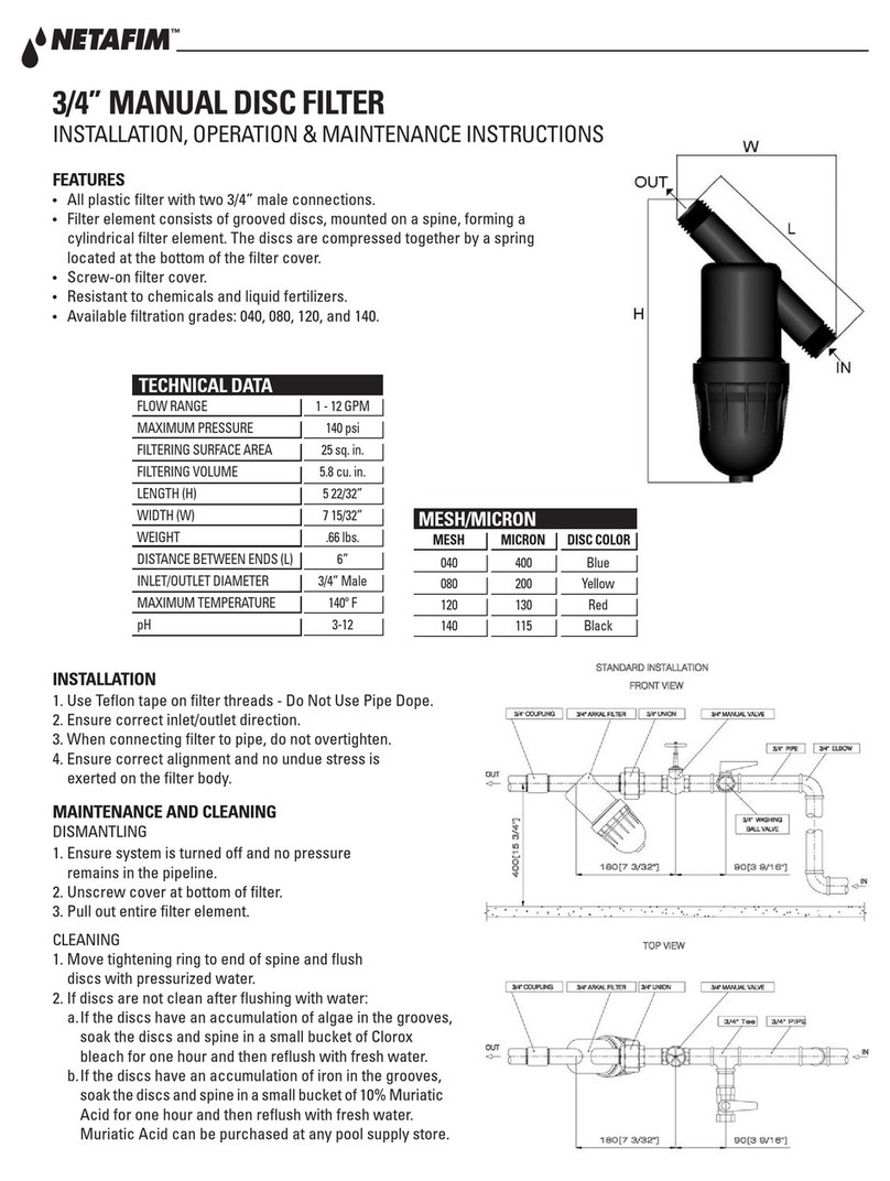
Netafim
Netafim 25AP46 Series Guide

Netafim
Netafim SCREENGUARD User manual
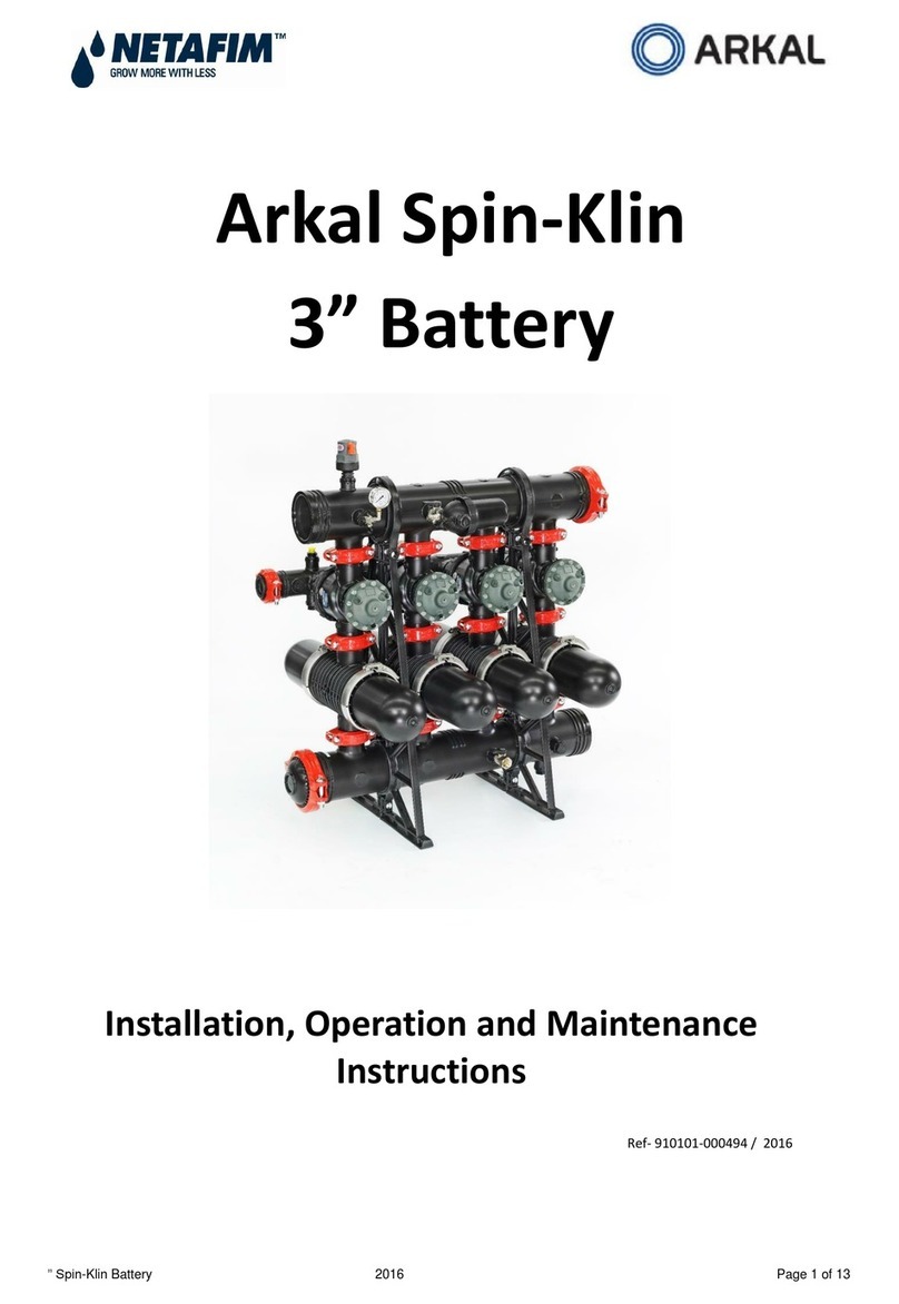
Netafim
Netafim Arkal 3" Spin-Klin Battery Installation and operating instructions

Netafim
Netafim SANDSTORM User manual
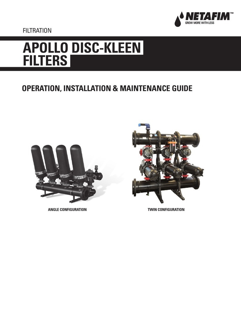
Netafim
Netafim APOLLO DISC-KLEEN Instruction Manual
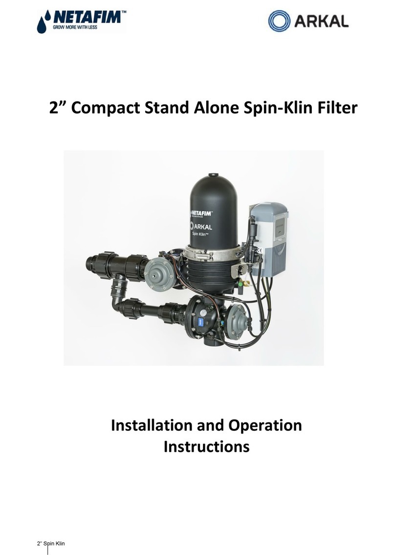
Netafim
Netafim Arkal 2" Spin-Klin Compact Stand Alone... User manual
