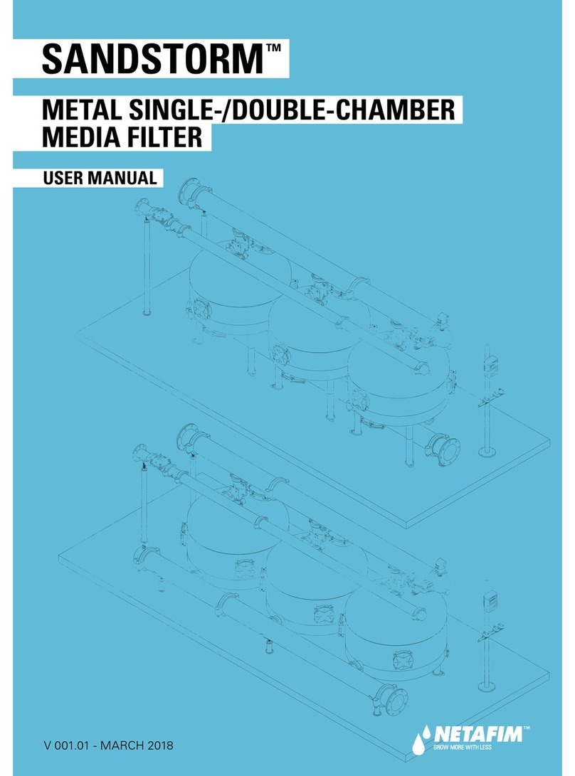
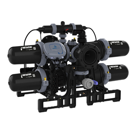
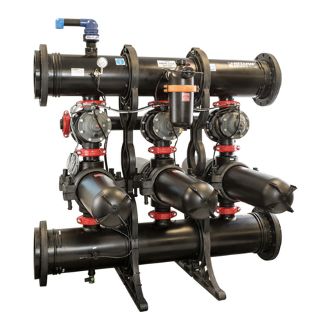
Netafim SANDSTORM User manual

V 001.01 - JANUARY 2020
INSTALLATION MANUAL
SANDSTORM
™
20", 24" TANKS
METAL DOUBLE-CHAMBER MEDIA FILTER

© COPYRIGHT 2020, NETAFIM™
NO PARTS OF THIS PUBLICATION MAY BE REPRODUCED, STORED IN AN AUTOMATED DATA FILE OR MADE PUBLIC IN
ANY FORM OR BY ANY MEANS, WHETHER ELECTRONIC, MECHANICAL, BY PHOTOCOPYING, RECORDING OR IN ANY
OTHER MANNER WITHOUT PRIOR WRITTEN PERMISSION OF THE PUBLISHER.
ALTHOUGH NETAFIM™TAKES THE GREATEST POSSIBLE CARE IN DESIGNING AND PRODUCING BOTH ITS PRODUCTS
AND THE ASSOCIATED DOCUMENTATION, THEY MAY STILL INCLUDE FAULTS.
NETAFIM™WILL NOT ACCEPT RESPONSIBILITY FOR DAMAGE RESULTING FROM THE USE OF NETAFIM'S PRODUCTS
OR THE USE OF THIS MANUAL.
NETAFIM™RESERVES THE RIGHT TO MAKE CHANGES AND IMPROVEMENTS TO ITS PRODUCTS AND/OR THE
ASSOCIATED DOCUMENTATION WITHOUT PRIOR NOTICE.
CONTENTS
Introduction
Aim of this manual
Safety instructions
General instructions
Components and structure
On-site pre-installation preparations
Tools required for installation
Flange connection
Grooved coupling connection
Installation
Initial operation
Troubleshooting
Warranty
3
3
4
4
5
6
6
7
8
16
18
19
FOREIGN LANGUAGES
In the event that you are reading this manual in a language other than English, you hereby
acknowledge and agree that the English language version shall prevail in case of inconsistency or
contradiction in interpretation or translation.

SANDSTORM
™
DOUBLE-CHAMBER INSTALLATION MANUAL 3
INTRODUCTION
Aim of this manual
The aim of this manual is to provide the technician with general instructions for the installation of any
configuration of the SandStorm™ metal double-chamber sand filtration system.
All system components are shipped to the site packed in pallets and boxes with installation drawings, user
manual, and a packing list.
NOTE
This manual describes the generic installation process of a SandStorm™ filtration system.
The installation should be carried out in line with the installation drawings supplied with the system.
Safety instructions
Before handling any part of the system, carefully read the instructions and act accordingly.
NOTE
The maximum working pressure of the filtration system is 8 bar (116 PSI).
(For filtration systems made to order, see the maximum working pressure in the Product Order).
Check and make sure the pumps and valves do not exceed the tolerances of the system and match the
requirements of the system pressure and flow-rate specifications (see the documentation supplied with
the system).
WARNING
Do not perform installation or maintenance operations or open filter ports before the pressure in the
system is fully released. For draining purposes, open any valve downstream from the filtration system
until the pressure is fully released. Check the pressure gauge to be sure it is at 0 before proceeding.
TIP
If a valve downstream from the filtration system is not available
for pressure release, you can install a manual valve on the lower
2" socket of the outlet manifold end-cap.
Electrical connections and wiring must be done by an authorized electrician only.
Be sure that prior to any maintenance procedures, all electrical connections to the system are unplugged
(AC controller, pumps, etc.).
Work only with proper and standard tools (see Tools required for installation, page 6).
Use only original parts supplied/approved by Netafim™.

4 SANDSTORM
™
DOUBLE-CHAMBER INSTALLATION MANUAL
INTRODUCTION
General instructions
•Installation must be performed by experienced and knowledgeable technicians.
•Consult with your supervisor if problems occur during installation.
•Do not apply excessive force or pressure on components during installation.
Electricity
•AC controller only: Ensure that a suitable electrical power supply is available in the vicinity of the
installation for electrical connection of the controller (see Electricity connection, page 5).
•An additional electrical socket should be available at the installation site for installation and service.
Components and structure
A media filtration system is comprised of the following components:
Media filter tank
Backwash 3-way
hydraulic valve
Backwash
flow-control
valve
Filtration system
control kit
Air valve
Inlet manifold
Outlet
manifold
Backwash
manifold
Grooved coupling
Manifold
support legs
Inlet flange adaptor
Outlet
flange adaptor
Backwash
flange adaptor
Backwash
controller
Solenoids
Location of
the tank ports
1Filling port
2Service port
1
2

SANDSTORM
™
DOUBLE-CHAMBER INSTALLATION MANUAL 5
Concrete slab construction
The sand filtration system will weigh anywhere
from 250 kg up to a few tons. The system
foundation must take into consideration the total
weight of the system when filled with sand and
water.
The media filtration system should be installed on
a concrete slab, at least 10 cm thick, with proper
reinforcement and anchored to the ground.
The dimensions given in the table on the right are
the
external filtration system dimensions
and not
the concrete slab dimensions
The minimum slab dimensions should allow a
sufficient margin around the filtration system for
service and maintenance.
The slab should have a slight grade to allow for
water run-off, but not so great that the manifold
does not bolt together easily.
The soil all around the slab should be compacted
to prevent erosion.
INTRODUCTION
On-site pre-installation preparations
The following items should be set up on site before the installation of the filtration system.
Electricity connection
The BackFlush controller is supplied in either of two versions:
•100-240v AC input - powered by an external 100-240v AC to 12v DC power supply.
Requires mains electricity supply - 100-240v AC ~, 50/60 Hz 0.4 A Max.
Ensure that suitable electrical power supply is available in the vicinity of the BackFlush controller
A readily accessible circuit breaker, rated according to the BackFlush controller's total rated power for
peak demand, certified as a branch circuit over current protector, compliant with the national code and
requirements. Grounding connection: ≤ 10 Ω.
•6v DC input - powered by 4 x 1.5v D-size alkaline batteries (not supplied).
Does not require mains electricity supply.
NOTE
If the filtration system was not ordered with a BackFlush controller and is intended to be connected
to an existing irrigation system controller, see the irrigation controller user manual for instructions.
No. of tanks
External filtration system
dimensions
(length/width/height)
Total system
weight**
cm inch kg lbs
20" tanks
2209/120/132 82/47/52 500 110 2
3269/120/132 106/47/52 750 1653
4329/120/132 130/47/52 1000 2205
5389/120/132 153/47/52 1250 2756
24" tanks
2249/120/132 98/47/52 720 1587
3329/120/132 130/47/52 1080 2381
4409/120/132 161/47/52 1440 3175
5489/120/132 193/47/52 1800 3968
Straight-line filtration systems*
*For other filtration system configurations,
contact your local Netafim™ representative.
**Filled with sand and water

6 SANDSTORM
™
DOUBLE-CHAMBER INSTALLATION MANUAL
INTRODUCTION
Tools required for installation
•No special tools are needed. A standard full installer toolkit is adequate.
•To connect the control stand to the concrete slab: An electrical hammering drill and a concrete drill bit.
•To connect grooved couplings: The following wrenches are required:
Grooved coupling size Bolt and nut size
(mm)
Wrench size
(mm)
inch mm
250 M10 17
380 M12 19
4100 M12 19
6150 M16 24
•To connect flanges: The following wrenches are required:
Flange size Bolt and nut size Wrench size
up to 8" 5/8" 15/16"
10" to 14" 7/8" 1.1/ 8 "
Backwash pipe
A pipe is necessary to take the backwash water from the backwash manifold back to the water source
(comply with your local regulations) or to the closest drainage ditch.
In order not to limit backwash flow rate:
•The backwash pipe should be no longer than 20 m (65 ft).
•The pipe diameter should never be smaller than the backwash manifold diameter.
•If the backwash pipe length is 10 meters (33 ft) or less, it should be of the same diameter as the
backwash manifold.
•If the backwash pipe is longer than 10 meters (33 ft), it should be of a larger diameter than the
backwash manifold.
•The pipe should not ascend above the elevation of the flushing manifold outlet.
Flange connection
In most cases, the filtration system manifolds are connected to the main line with flanges.
ATTENTION
When connecting flange pipe connectors, do not forget to place the rubber gasket in place.

SANDSTORM
™
DOUBLE-CHAMBER INSTALLATION MANUAL 7
INTRODUCTION
Grooved coupling connection
All the main filtration system parts are connected with grooved couplings.
To connect a grooved coupling:
REV.
DESCRIPTION
DATE
APPROVED
Drawing No.
QA
Project:
3.slddrw
File Name:
General Tolerance According to ISO 2768-f
LINEAR DIMENSIONS
ANGULAR DIMENSIONS
Permissible deviations in mm for ranges in nominal lengths
Permissible deviations in degrees and minutes
for ranges in nominal lengths
3-D Proj.
Part No.
Scale:
Sheet Size:
A3
Drawn By
Designed By
Subject:
Checked By
Part Name:
Material:
1:5
Finish:
Sheet:
Of:
1 1
PROPRIETARY AND CONFIDENTIAL
THE INFORMATION CONTAINED IN THIS
DRAWING IS THE SOLE PROPERTY OF
NETAFIM. ANY REPRODUCTION IN PART
OR AS A WHOLE WITHOUT THE WRITTEN
PERMISSION OF NETAFIM IS PROHIBITED
Rev.
/1
Quantity:
±1°
±0.05
≥ 0.5
≤ 3
> 3
≤ 6
> 6
≤ 30
> 30
≤ 120
> 120
≤ 400
> 400
≤ 1000
> 1000
≤ 2000
> 2000
≤ 4000
≤ 10
> 400
> 120
≤ 400
> 50
≤ 120
> 10
≤ 50
±0°30'
±0°20'
±0°10'
±0°5'
±0.15
±0.1
±0.05
±0.2
±0.3
-
±0.5
REV.
DESCRIPTION
DATE
APPROVED
Drawing No.
QA
Project:
6.slddrw
File Name:
General Tolerance According to ISO 2768-f
LINEAR DIMENSIONS
ANGULAR DIMENSIONS
Permissible deviations in mm for ranges in nominal lengths
Permissible deviations in degrees and minutes
for ranges in nominal lengths
3-D Proj.
Part No.
Scale:
Sheet Size:
A3
Drawn By
Designed By
Subject:
Checked By
Part Name:
Material:
1:5
Finish:
Sheet:
Of:
1 1
PROPRIETARY AND CONFIDENTIAL
THE INFORMATION CONTAINED IN THIS
DRAWING IS THE SOLE PROPERTY OF
NETAFIM. ANY REPRODUCTION IN PART
OR AS A WHOLE WITHOUT THE WRITTEN
PERMISSION OF NETAFIM IS PROHIBITED
Rev.
/1
Quantity:
±1°
±0.05
≥ 0.5
≤ 3
> 3
≤ 6
> 6
≤ 30
> 30
≤ 120
> 120
≤ 400
> 400
≤ 1000
> 1000
≤ 2000
> 2000
≤ 4000
≤ 10
> 400
> 120
≤ 400
> 50
≤ 120
> 10
≤ 50
±0°30'
±0°20'
±0°10'
±0°5'
±0.15
±0.1
±0.05
±0.2
±0.3
-
±0.5
REV.
DESCRIPTION
DATE
APPROVED
Drawing No.
QA
Project:
8.slddrw
File Name:
General Tolerance According to ISO 2768-f
LINEAR DIMENSIONS
ANGULAR DIMENSIONS
Permissible deviations in mm for ranges in nominal lengths
Permissible deviations in degrees and minutes
for ranges in nominal lengths
3-D Proj.
Part No.
Scale:
Sheet Size:
A3
Drawn By
Designed By
Subject:
Checked By
Part Name:
Material:
1:5
Finish:
Sheet:
Of:
1 1
PROPRIETARY AND CONFIDENTIAL
THE INFORMATION CONTAINED IN THIS
DRAWING IS THE SOLE PROPERTY OF
NETAFIM. ANY REPRODUCTION IN PART
OR AS A WHOLE WITHOUT THE WRITTEN
PERMISSION OF NETAFIM IS PROHIBITED
Rev.
/1
Quantity:
±1°
±0.05
≥ 0.5
≤ 3
> 3
≤ 6
> 6
≤ 30
> 30
≤ 120
> 120
≤ 400
> 400
≤ 1000
> 1000
≤ 2000
> 2000
≤ 4000
≤ 10
> 400
> 120
≤ 400
> 50
≤ 120
> 10
≤ 50
±0°30'
±0°20'
±0°10'
±0°5'
±0.15
±0.1
±0.05
±0.2
±0.3
-
±0.5
REV.
DESCRIPTION
DATE
APPROVED
Drawing No.
QA
Project:
7.slddrw
File Name:
General Tolerance According to ISO 2768-f
LINEAR DIMENSIONS
ANGULAR DIMENSIONS
Permissible deviations in mm for ranges in nominal lengths
Permissible deviations in degrees and minutes
for ranges in nominal lengths
3-D Proj.
Part No.
Scale:
Sheet Size:
A3
Drawn By
Designed By
Subject:
Checked By
Part Name:
Material:
1:5
Finish:
Sheet:
Of:
1 1
PROPRIETARY AND CONFIDENTIAL
THE INFORMATION CONTAINED IN THIS
DRAWING IS THE SOLE PROPERTY OF
NETAFIM. ANY REPRODUCTION IN PART
OR AS A WHOLE WITHOUT THE WRITTEN
PERMISSION OF NETAFIM IS PROHIBITED
Rev.
/1
Quantity:
±1°
±0.05
≥ 0.5
≤ 3
> 3
≤ 6
> 6
≤ 30
> 30
≤ 120
> 120
≤ 400
> 400
≤ 1000
> 1000
≤ 2000
> 2000
≤ 4000
≤ 10
> 400
> 120
≤ 400
> 50
≤ 120
> 10
≤ 50
±0°30'
±0°20'
±0°10'
±0°5'
±0.15
±0.1
±0.05
±0.2
±0.3
-
±0.5
REV.
DESCRIPTION
DATE
APPROVED
Drawing No.
QA
Project:
3.slddrw
File Name:
General Tolerance According to ISO 2768-f
LINEAR DIMENSIONS
ANGULAR DIMENSIONS
Permissible deviations in mm for ranges in nominal lengths
Permissible deviations in degrees and minutes
for ranges in nominal lengths
3-D Proj.
Part No.
Scale:
Sheet Size:
A3
Drawn By
Designed By
Subject:
Checked By
Part Name:
Material:
1:5
Finish:
Sheet:
Of:
1 1
PROPRIETARY AND CONFIDENTIAL
THE INFORMATION CONTAINED IN THIS
DRAWING IS THE SOLE PROPERTY OF
NETAFIM. ANY REPRODUCTION IN PART
OR AS A WHOLE WITHOUT THE WRITTEN
PERMISSION OF NETAFIM IS PROHIBITED
Rev.
/1
Quantity:
±1°
±0.05
≥ 0.5
≤ 3
> 3
≤ 6
> 6
≤ 30
> 30
≤ 120
> 120
≤ 400
> 400
≤ 1000
> 1000
≤ 2000
> 2000
≤ 4000
≤ 10
> 400
> 120
≤ 400
> 50
≤ 120
> 10
≤ 50
±0°30'
±0°20'
±0°10'
±0°5'
±0.15
±0.1
±0.05
±0.2
±0.3
-
±0.5
REV.
DESCRIPTION
DATE
APPROVED
Drawing No.
QA
Project:
5.slddrw
File Name:
General Tolerance According to ISO 2768-f
LINEAR DIMENSIONS
ANGULAR DIMENSIONS
Permissible deviations in mm for ranges in nominal lengths
Permissible deviations in degrees and minutes
for ranges in nominal lengths
3-D Proj.
Part No.
Scale:
Sheet Size:
A3
Drawn By
Designed By
Subject:
Checked By
Part Name:
Material:
1:5
Finish:
Sheet:
Of:
1 1
PROPRIETARY AND CONFIDENTIAL
THE INFORMATION CONTAINED IN THIS
DRAWING IS THE SOLE PROPERTY OF
NETAFIM. ANY REPRODUCTION IN PART
OR AS A WHOLE WITHOUT THE WRITTEN
PERMISSION OF NETAFIM IS PROHIBITED
Rev.
/1
Quantity:
±1°
±0.05
≥ 0.5
≤ 3
> 3
≤ 6
> 6
≤ 30
> 30
≤ 120
> 120
≤ 400
> 400
≤ 1000
> 1000
≤ 2000
> 2000
≤ 4000
≤ 10
> 400
> 120
≤ 400
> 50
≤ 120
> 10
≤ 50
±0°30'
±0°20'
±0°10'
±0°5'
±0.15
±0.1
±0.05
±0.2
±0.3
-
±0.5
a.
Slide the rubber gasket onto
the end of one of the pipes to
be connected.
Apply a dedicated lubricant
or liquid soap to the coupling
rubber gasket to facilitate
insertion.
b.
Place the end of the other pipe
to be connected so that it
touches the end of the first pipe,
and slide the rubber gasket
over the end of the second pipe.
The rubber gasket should cover
the end of both pipes equally,
leaving the groove of each pipe
exposed.
c.
Place the two housing elements
around the rubber gasket. Make
sure the rims of the housing
elements are inserted into the
grooves all around both pipes.
d.
Put the bolts and nuts in place
and close them to a tight fit, but
do not fasten them yet.
e.
When you are satisfied that
the connected parts are properly
positioned and the connections
are properly aligned, fasten the
two nuts alternately until the
coupling is evenly tightened
around both pipes.
a
b
c
d e
8 SANDSTORM
™
DOUBLE-CHAMBER INSTALLATION MANUAL
INSTALLATION
This chapter describes the generic installation process of a SandStorm™ filtration system. The installation
should be carried out in line with the installation drawings supplied with the system.
1.
Align the gravel tanks on the platform according to the dimensions in the table.
2.
Connect a nipple to each tank inlet.
a
a
a
a
1
ATTENTION
To enable the connection of the manifolds,
position all the tanks with the intlet 1pointing
exactly to the front.
*The distances in this table are for straight-
line systems. For the distance between
adjacent rows of tanks in other
system
configurations, see the installation
drawings
supplied with the system.
Tank size
Distance between tanks - center to center (a)
cm inch
20" 60 23.62
24" 80 31.50

SANDSTORM
™
DOUBLE-CHAMBER INSTALLATION MANUAL 9
NOTE
The manifolds are supported by support legs. Each support leg should be installed immediately after
installing the part it supports. Place the support legs according to their quantity and locations in the
system installation drawings.
Use the long support legs to support the inlet manifold, the medium legs
to support the backwash manifold and the short legs to support the outlet manifold.
INSTALLATION
3.
Connect the backwash manifold to the backwash valves
and the backwash manifold sections to each other
with grooved couplings.
2.
Connect a
backwash
valve to each nipple.
Be sure that the position of the backwash valves
is per the flow arrows marked on the valve.

10 SANDSTORM
™
DOUBLE-CHAMBER INSTALLATION MANUAL
5.
Connect the outlet manifold to the
outlets of the tanks and the outlet
manifold sections to each other
with grooved couplings.
6.
Check and confirm that the position of the system is where it should be relative to the inlet and outlet
main pipelines. Readjust the filtration system location if needed.
INSTALLATION
4.
Connect the inlet manifold to the backwash valves
and the inlet manifold sections to each other
with grooved couplings.

SANDSTORM
™
DOUBLE-CHAMBER INSTALLATION MANUAL 11
INSTALLATION
7.
Connect the backwash nipple with a grooved
coupling. Make sure that the backwash nipple is
placed with the socket for the valve-command
pointing upwards.
8.
Connect the backwash flow-control valve with a
grooved coupling. Be sure that the position of the
valve is per the flow arrow marked on the valve.
a.
Connect the valve-command water-supply
assembly to the dedicated socket of the backwash
nipple.
ATTENTION
Cut the PE 8 mm command tubes to the
required length.
To avoid kinks, the PE 8 mm command
tubes should be of the right length to form
regular curves.
b.
Connect a PE 8 mm command tube from the high
pressure point of the valve to the valve-command
water-supply assembly.
c.
Connect a PE 8 mm command tube from
the high pressure point of the pilot to the
valve-command water-supply assembly.
d.
The valve is supplied with the suitable
orifice plate for the specific filtration
system. Before installing the valve, make
sure that the orifice plate is in its place
inside the valve inlet.
C
23
4
1
5
FR
2M
2M A
O
Flow Control Valve
100
Application Engineering www.dorot.com
Rev. 0GN
21/06/2016 1/03/2017
FR - Flow Control Valve.vsd
Scale: N\A
FR
A
PPLICATION
D
RAWING
2"-6" \50mm – 150mm
N\A
b
c
ad
Backwash flow-control valve setup

12 SANDSTORM
™
DOUBLE-CHAMBER INSTALLATION MANUAL
INSTALLATION
11.
Connect the end-cap to the outlet manifold with
a grooved coupling. Make sure that the end-
cap is placed with the socket for the air valve
pointing upwards and the socket for the control
assembly pointing sideways.
NOTE
The filtration system is supplied with flange
adaptors for its connection to the main line
and backwash pipe. Some installations do not
require flange adaptors since the main line
and backwash pipes comply with the grooved
coupling standard. In such cases, skip
steps 12, 13 and 14 below. Simply connect
the filtration system to the main line and
backwash pipe with grooved couplings.
12.
Connect the flange adaptor to the inlet manifold
with a grooved coupling.
13.
Connect the flange adaptor to the outlet
manifold with a grooved coupling.
9.
Connect the end-cap to the backwash manifold
with a grooved coupling.
10.
Connect the end-cap to the inlet manifold with a
grooved coupling. Make sure that the end-cap is
placed with the socket for the air valve pointing
upwards and the socket for the control assembly
pointing sideways.
NOTE
If the
filtration system is supplied with an
inlet adaptor pipe (ordered separately),
connect the inlet adaptor pipe to the inlet
manifold with a grooved coupling and then
connect the flange adaptors to the inlet
adaptor pipe with a grooved coupling.

SANDSTORM
™
DOUBLE-CHAMBER INSTALLATION MANUAL 13
INSTALLATION
14.
Connect the flange adaptor to the backwash
flow-control valve with a grooved coupling.
16.
Connect the control assembly to the socket on
the side of the inlet manifold end-cap.
17.
Place the stand of the backwash controller so
that it is close to the control assembly (make
sure it meets your needs for both operation and
maintenance). Secure it to the concrete slab with
10 mm spreading anchor bolts (not supplied).
15.
Connect the air valve to the socket on the top of
the inlet manifold end-cap.
18.
Secure the BackFlush controller and the solenoid
bracket in place on the stand.

14 SANDSTORM
™
DOUBLE-CHAMBER INSTALLATION MANUAL
INSTALLATION
19.
Connect the PE 8 mm command tubes:
a.
From the low pressure point in the BackFlush controller to the low pressure point socket on the
end cap of the outlet manifold of the gravel filtration system (find the accessories in the control kit).
b.
From one of the outlets on the 3-way ball valve of the control kit to the low pressure point socket on
the end cap of the outlet manifold (find the accessories in the control kit).
c.
From the outlet of the water control kit to the common “live pressure” inlets of the solenoids.
d.
From the outlet of the water control kit to the high pressure point of the BackFlush controller.
e.
From each solenoid command outlet to one of the hydraulic backwash valves, in order of sequence.
f.
Connect a drain tube (no more than 2 meters) to the common vent of the solenoids.
g.
Secure the PE 8 mm command tubes with plastic zip ties in an organized and tidy fashion along the
filtration system.
REV.
DESCRIPTION
DATE
APPROVED
Drawing No.
QA
Project:
A-24077-110117
CONTROLLER STAND +valves +control head.slddrw
File Name:
General Tolerance According to ISO 2768-f
LINEAR DIMENSIONS
ANGULAR DIMENSIONS
Permissible deviations in mm for ranges in nominal lengths
Permissible deviations in degrees and minutes
for ranges in nominal lengths
3-D Proj.
Part No.
Scale:
Sheet Size:
A3
Drawn By
Designed By
CONTROLLER STAND + DC VALVE
25/01/2017
Barga
Subject:
Checked By
Part Name:
Material:
1:50
Finish:
Sheet:
Of:
1 1
PROPRIETARY AND CONFIDENTIAL
THE INFORMATION CONTAINED IN THIS
DRAWING IS THE SOLE PROPERTY OF
NETAFIM. ANY REPRODUCTION IN PART
OR AS A WHOLE WITHOUT THE WRITTEN
PERMISSION OF NETAFIM IS PROHIBITED
Rev.
/1
Quantity:
±1°
±0.05
≥ 0.5
≤ 3
> 3
≤ 6
> 6
≤ 30
> 30
≤ 120
> 120
≤ 400
> 400
≤ 1000
> 1000
≤ 2000
> 2000
≤ 4000
≤ 10
> 400
> 120
≤ 400
> 50
≤ 120
> 10
≤ 50
±0°30'
±0°20'
±0°10'
±0°5'
±0.15
±0.1
±0.05
±0.2
±0.3
-
±0.5
REV.
DESCRIPTION
DATE
APPROVED
Drawing No.
QA
Project:
MTL SNG 480308 front color.slddrw
File Name:
General Tolerance According to ISO 2768-f
LINEAR DIMENSIONS
ANGULAR DIMENSIONS
Permissible deviations in mm for ranges in nominal lengths
Permissible deviations in degrees and minutes
for ranges in nominal lengths
3-D Proj.
Part No.
Scale:
Sheet Size:
A3
Drawn By
Designed By
MTL SNG 480308 S D08 BFC DC SOL DC
NGR
13/02/2017
Barga
Subject:
Checked By
Part Name:
Material:
1:50
Finish:
Sheet:
Of:
1 1
PROPRIETARY AND CONFIDENTIAL
THE INFORMATION CONTAINED IN THIS
DRAWING IS THE SOLE PROPERTY OF
NETAFIM. ANY REPRODUCTION IN PART
OR AS A WHOLE WITHOUT THE WRITTEN
PERMISSION OF NETAFIM IS PROHIBITED
Rev.
/1
Quantity:
±1°
±0.05
≥ 0.5
≤ 3
> 3
≤ 6
> 6
≤ 30
> 30
≤ 120
> 120
≤ 400
> 400
≤ 1000
> 1000
≤ 2000
> 2000
≤ 4000
≤ 10
> 400
> 120
≤ 400
> 50
≤ 120
> 10
≤ 50
±0°30'
±0°20'
±0°10'
±0°5'
±0.15
±0.1
±0.05
±0.2
±0.3
-
±0.5
a
b
c
d
e
ab
d
e e
f
cLive pressure
eCommand
fVent
REV.
DESCRIPTION
DATE
APPROVED
Drawing No.
QA
Project:
A-24154-120117
AQUATIV DC(CV 606)SINGLE KIT CONF 2 3MM - 35500-001925.slddrw
File Name:
General Tolerance According to ISO 2768-f
LINEAR DIMENSIONS
ANGULAR DIMENSIONS
Permissible deviations in mm for ranges in nominal lengths
Permissible deviations in degrees and minutes
for ranges in nominal lengths
3-D Proj.
Part No.
Scale:
Sheet Size:
A3
Drawn By
Designed By
AQUATIV DC(CV 606)SINGLE KIT CONF 2
3MM - 35500-001925
12/01/2017
Barga
Subject:
Checked By
Part Name:
Material:
1:50
Finish:
Sheet:
Of:
1 1
PROPRIETARY AND CONFIDENTIAL
THE INFORMATION CONTAINED IN THIS
DRAWING IS THE SOLE PROPERTY OF
NETAFIM. ANY REPRODUCTION IN PART
OR AS A WHOLE WITHOUT THE WRITTEN
PERMISSION OF NETAFIM IS PROHIBITED
Rev.
/1
Quantity:
±1°
±0.05
≥ 0.5
≤ 3
> 3
≤ 6
> 6
≤ 30
> 30
≤ 120
> 120
≤ 400
> 400
≤ 1000
> 1000
≤ 2000
> 2000
≤ 4000
≤ 10
> 400
> 120
≤ 400
> 50
≤ 120
> 10
≤ 50
±0°30'
±0°20'
±0°10'
±0°5'
±0.15
±0.1
±0.05
±0.2
±0.3
-
±0.5
c
fe
Outlet
manifold
end cap
REV.
DESCRIPTION
DATE
APPROVED
Drawing No.
QA
Project:
A-24077-110117
CONTROLLER STAND +valves +control head.slddrw
File Name:
General Tolerance According to ISO 2768-f
LINEAR DIMENSIONS
ANGULAR DIMENSIONS
Permissible deviations in mm for ranges in nominal lengths
Permissible deviations in degrees and minutes
for ranges in nominal lengths
3-D Proj.
Part No.
Scale:
Sheet Size:
A3
Drawn By
Designed By
CONTROLLER STAND + DC VALVE
25/01/2017
Barga
Subject:
Checked By
Part Name:
Material:
1:50
Finish:
Sheet:
Of:
1 1
PROPRIETARY AND CONFIDENTIAL
THE INFORMATION CONTAINED IN THIS
DRAWING IS THE SOLE PROPERTY OF
NETAFIM. ANY REPRODUCTION IN PART
OR AS A WHOLE WITHOUT THE WRITTEN
PERMISSION OF NETAFIM IS PROHIBITED
Rev.
/1
Quantity:
±1°
±0.05
≥ 0.5
≤ 3
> 3
≤ 6
> 6
≤ 30
> 30
≤ 120
> 120
≤ 400
> 400
≤ 1000
> 1000
≤ 2000
> 2000
≤ 4000
≤ 10
> 400
> 120
≤ 400
> 50
≤ 120
> 10
≤ 50
±0°30'
±0°20'
±0°10'
±0°5'
±0.15
±0.1
±0.05
±0.2
±0.3
-
±0.5
e e
e ee e
20.
Connect the solenoids to the BackFlush controller expansion cards in sequence, from left to right.
Red wire = + / black wire = common (inversing wire polarity will change NC to NO).
ATTENTION
The solenoids must be of the 12v DC latching type.
a.
Connect 2 solenoids
to each
expansion card.
b.
If there is an odd number
of filters in the system, connect
the last one as illustrated.
(For full instructions, see the BackFlush
controller manual).
a b
REV.
DESCRIPTION
DATE
APPROVED
Drawing No.
QA
Project:
A-24154-120117
AQUATIV DC(CV 606)SINGLE KIT CONF 2 3MM - 35500-001925.slddrw
File Name:
General Tolerance According to ISO 2768-f
LINEAR DIMENSIONS
ANGULAR DIMENSIONS
Permissible deviations in mm for ranges in nominal lengths
Permissible deviations in degrees and minutes
for ranges in nominal lengths
3-D Proj.
Part No.
Scale:
Sheet Size:
A3
Drawn By
Designed By
AQUATIV DC(CV 606)SINGLE KIT CONF 2
3MM - 35500-001925
12/01/2017
Barga
Subject:
Checked By
Part Name:
Material:
1:50
Finish:
Sheet:
Of:
1 1
PROPRIETARY AND CONFIDENTIAL
THE INFORMATION CONTAINED IN THIS
DRAWING IS THE SOLE PROPERTY OF
NETAFIM. ANY REPRODUCTION IN PART
OR AS A WHOLE WITHOUT THE WRITTEN
PERMISSION OF NETAFIM IS PROHIBITED
Rev.
/1
Quantity:
±1°
±0.05
≥ 0.5
≤ 3
> 3
≤ 6
> 6
≤ 30
> 30
≤ 120
> 120
≤ 400
> 400
≤ 1000
> 1000
≤ 2000
> 2000
≤ 4000
≤ 10
> 400
> 120
≤ 400
> 50
≤ 120
> 10
≤ 50
±0°30'
±0°20'
±0°10'
±0°5'
±0.15
±0.1
±0.05
±0.2
±0.3
-
±0.5
c

SANDSTORM
™
DOUBLE-CHAMBER INSTALLATION MANUAL 15
INSTALLATION
NOTE
If the filtration system was not ordered with a BackFlush controller and is intended to be connected
to an existing irrigation system controller, see the irrigation controller user manual for instructions.
NOTE
If the filtration system was not ordered with a BackFlush controller and is intended to be connected
to an existing irrigation system controller, see the irrigation controller user manual for instructions.
21.
Connect the BackFlush controller to the electricity source:
A.
For controllers powered by an external 12v DC power supply
WARNING
When operating the controller with the external power supply, make sure there are no batteries in
the battery
tray
.
•Connect the external 100-240v AC to 12v DC power supply
to the BackFlush controller 12v DC input.
Red wire = + / black wire = -.
•Connect the power supply to a water-resistant socket.
B.
For controllers powered by 4 x 1.5v D-size
alkaline
batteries (6v DC)
•Connect the battery tray to the BackFlush controller
6v DC input.
•Insert the batteries.
Match the poles to the markings
inside the battery
tray
.
(For full instructions, see the BackFlush controller manual).
22.
Close all the openings of the manifold end caps with the plugs supplied with the control kit.
(1" plugs for systems up to 24", 2" plugs for systems 30" and up).
24.
Connect the backwash pipe to the flange of the backwash manifold
(see the NOTE under step 11, page 12).
25.
Visually check (with the aid of a flashlight) the inside of all the tanks, through the filling port, for
damaged, missing or unsecured under-drain diffusers ("mushrooms"). Replace, re-fit, re-connect and
re-secure if necessary.
26.
Fill the tanks with media through the filling port.
Fill each tank up to the media level marker on the filter tank.
27.
Flatten the surface of the media.
28.
Make sure that the filling port and its gasket are clear of any
remaining gravel particles and close the filling port.
23.
Connect the filtration system inlet and outlet to the main irrigation line with flanges
(see the NOTE under step 11, page 12).
Tank diameter
(inch)
Sand quantity*
kg lbs
20 120 265
24 180 397
*Crushed basalt.
Add-ons recommended to install (optional)
•A secondary (screen) filter on the main line, downstream from the media filtration system.
•A manual isolation valve downstream from the media filtration system for maintenance purposes.

16 SANDSTORM
™
DOUBLE-CHAMBER INSTALLATION MANUAL
DP ACTUAL
DP SET
FLUSH
TIME
FLUSH
MODE
BARSec Hours
MANUAL
ENTER
The actual DP value.
Available only when the built-in
electronic DP sensor is used.
The DP set-point.
Available only when the built-in
electronic DP sensor is used.
The desired
flushing time
per station. The desired flushing mode.
Contains either the flushing
interval or, when the flushing
is triggered by DP only, the
letters “DP.”
1.
Set the BackFlush controller
The controller is equipped with an LCD display and 4 keys, as displayed below. When the unit is left
untouched for a minute, the display switches off and a beep is heard every 20 seconds to indicate it is
working.
Holding down any of the keys for a few seconds will bring the screen back to life.
The screen consists of several fields. Some of them are editable and some of them are not.
To enter the EDIT MODE, press the key. The EDIT MODE is indicated by blinking of the currently
editable field.
Each time you press the key, the next editable field becomes active and starts blinking.
Use the and keys to change the value in the active field.
Press the key again to set the selected value for the current field and move to the next editable field.
To return to a previous field during the process of passing through the editable fields, press the key
repeatedly until you get back to the FLUSH TIME field, and there are blinking fields. You can then begin
the process again.
Configuration
INITIAL OPERATION
Parameter Definition Action
Main valve
(sustaining valve)
The pre-dwell delay between the main valve
opening and the opening of station 1
Select:
YES
if exists
Enter:
20 sec
Dwell time
The backwashing delay between stations Enter:
10 sec
DP delay
The delay during which the DP sensor reading
is expected to remain stable before reaction
Enter:
10 sec
Looping limit
The number of consecutive flushing cycles
triggered by the DP sensor before deciding
that there is an endless looping problem
Enter:
3
Alarm
Allocates one output for alarm activation Select:
YES
Delay valve
Allocates one output for delay-valve activation Select:
YES
if exists
(continued on the next page)

SANDSTORM
™
DOUBLE-CHAMBER INSTALLATION MANUAL 17
Parameter Definition Action
View outputs
This is a special mode that enables the user to
review the list of outputs and their allocations.
The output number is displayed in the bottom
left corner and its allocated function appears in
large letters in the center of the screen
Use the
key to toggle between
NO and YES and confirm by
pressing
the key
. Keep using
the
key to review the list
Pressure units
Select the units to be used for pressure
measurement
Select:
BAR
or
PSI
Calibration
Zero calibration of the built-in electronic DP
sensor.
Disconnect the sensor ports from
the command tube and open them
to atmospheric pressure;
then select calibration:
YES
Version display
Displays the controller's software version-
number.
No action required.
Press the key twice to
proceed.
Flush time
The desired flushing time per station. Enter:
100 sec
DP set-point
The pressure difference between the filter’s
inlet and outlet that initiates a flushing cycle.
Enter:
0.7 bar
or
10 PSI
Flush mode
The flushing interval or, when the flushing is
triggered by DP only, the letters “DP.”
Enter:
3 hours
INITIAL OPERATION
Configuration (continued)
(For full instructions, see the BackFlush controller manual).
NOTE
If the filtration system was not ordered with a BackFlush controller and is used with an existing
irrigation system controller, see your irrigation controller user manual for instructions.
2.
Turn on the water and start irrigation.
3.
As soon as the system is pressurized and stable. Start a manual backwashing cycle by pressing the
key. The icon will appear on the display (to manually terminate a backwashing cycle in progress,
press the same key).
4.
After completion of a full backwashing cycle, check that the filtration system DP is within the operational
range (0.15-0.4 bar/2.2-5.8 PSI, depending on the flow rate). Toggle the control kit 3-way ball valve and
note the filtration system inlet and outlet pressure. Subtract the outlet pressure from the inlet pressure.
The result is the filtration system DP.
5.
Check all the filtration system connections for water leaks – re-fit, re-connect and re-secure if necessary.
6.
Check all the command tube connections for leaks – re-fit, re-connect, and re-secure if necessary.
7.
Check that the backwashing cycle is performed in the correct order and that all the filters in the system
are backwashed in sequence.
8.
Check the secondary filter (if installed) for the presence of gravel.
NOTE
If a secondary filter is not installed, disconnect the main line pipe downstream from the filtration
system, let the water flow to the ground and visually check for the presence of gravel.
If gravel is present, see Troubleshooting, page 18.
ATTENTION
Steps
2
to
8
above should be performed whenever the operation of the filtration system is resumed
after being idle (i.e., after seasonal shutdown, maintenance or troubleshooting operations).

18 SANDSTORM
™
DOUBLE-CHAMBER INSTALLATION MANUAL
TROUBLESHOOTING
If the flushing cycle does not start but the controller is initiating the flushing signal and the solenoids
are reacting (“clicking”):
1.
Check the command filter in the control assembly. Clean it if necessary and perform manual flushing.
2.
Check for clogging inside the solenoid valves - clean if possible or replace with a new solenoid.
3.
Check for clogging of the hydraulic control tubes - open the clogs and clean if necessary.
4.
Check for a ruptured or defective hydraulic control tube - replace if necessary.
If the media is running out through the outlet manifold during filtration:
1.
Depressurize the system.
2.
Disconnect the outlet manifold and visually identify which filter tank is losing gravel.
Alternatively, you can open the filling ports of the tanks, one by one, and visually identify the tank in
which the media level has dropped.
ATTENTION
There may be more than one tank losing gravel.
3.
Empty the media from the tank/s and replace the damaged under-drain diffuser/s ("mushrooms") inside
the tank/s.
4.
Refill the tank with media (see instructions in the Installation chapter, steps 26-28, page 15).
If the media is running out through the backwash manifold during backwash:
1.
Adjust the backwash flow-control valve on the backwash manifold.
•If a manual backwash flow-control valve is installed, throttle the valve to reduce the flow until the
media stops running out.
•If a hydraulic backwash flow-control valve is installed, the valve is factory pre-set to the required
flow rate.
In the rare case that the backwash flow-control valve requires fine-tuning:
a.
Release the pilot lock-nut.
b.
Gently rotate the pilot calibration bolt counterclockwise with a wrench to reduce the flow until the
media stops running out.
c.
Retighten the pilot lock-nut.
2.
Check the level of media inside the filters.
•If the level is lower than the media level marker on the filter tank - add media.
•If the level is higher than the media level marker on the filter tank - remove media.
WARNING
Do not perform maintenance operations or open filter ports before the pressure in the system is
fully released. For draining purposes, open any valve downstream from the filtration system until
the pressure is fully released. Check the pressure gauge to be sure it is at 0 before proceeding.
Alternatively, you can open the valve installed on the outlet manifold end-cap - if installed (see TIP,
page 3).

SANDSTORM
™
DOUBLE-CHAMBER INSTALLATION MANUAL 19
WARRANTY
Netafim™ warrants all the components of the SandStorm™/SandStorm™ NC media filter system to be
free of defects in material and workmanship for 5 (five) years from the date of installation.
If a defect is discovered during the applicable warranty period, Netafim™ will repair or replace, at its
discretion, the product or the defective part.
This warranty does not extend to repairs, adjustments or replacements of a Netafim™ media filter system
or part that results from misuse, negligence, alteration, force majeure, lightning, power surge, improper
installation or improper maintenance.
If a defect arises in your Netafim™ product during the warranty period, contact your local Netafim™
representative.
Limited warranty
This warranty is subject to the conditions in Netafim's official warranty statement.
(For the full text of Netafim's official warranty statement, please contact your local Netafim™
representative).
Other manuals for SANDSTORM
2
Table of contents
Other Netafim Water Filtration System manuals

Netafim
Netafim SANDSTORM User manual

Netafim
Netafim Arkal 3" Spin-Klin Battery Installation and operating instructions

Netafim
Netafim Apollo Instruction Manual

Netafim
Netafim AlphaDisc Series User manual

Netafim
Netafim Arkal 3" Spin-Klin Battery User manual

Netafim
Netafim Arkal 2" Spin-Klin Compact Stand Alone... User manual

Netafim
Netafim 25AP46 Series Guide

Netafim
Netafim Amiad Mini Sigma 2 1200 User manual

Netafim
Netafim SCREENGUARD User manual

Netafim
Netafim APOLLO DISC-KLEEN Instruction Manual